Note: Descriptions are shown in the official language in which they were submitted.
1 20 ~ 42~0.~
PROSTHETIC FOOT HAVING A LOW PROFILE
CANTILEVER SPRING HEEL
Technical Field
The present invention relates to a prosthetic foot, and more particularly to a
prosthetic foot utilizing an energy storing, low profile cantilever spring
keel
attachable to a leg prosthesis at substantially the location of a natural
ankle joint.
Back ,round of the Invention
Although prosthetic feet have been in use for many years, not until
relatively recently have efforts been made to design the prosthetic feet to
dynamically interact with the cyclic loading and unloading of the foot during
body
movements thereby to more closely simulate natural body movement and gait. To
this end, such prostheses typically are configured to store and release energy
during normal body movements.
One such type of prosthesis is disclosed by U.S. Patent No. 4,547,913 which
concerns a prosthetic device having an upwardly extending leg portion, a foot
portion extending forwardly from the bottom of the leg portion and a heel
portion
extending rearwardly from the bottom of the leg portion, with all three
portions
rigidly joined together. The three portions of the prosthesis are composed of
elastic, flexible material to absorb strain energy and thereafter release the
energy
during leg and foot movement. A substantial drawback of the prosthesis
disclosed
in the '913 patent is that the leg portion of the prosthesis precludes it from
serving as only a foot prosthesis. Moreover, the spring rate of the foot
portion of
the prosthesis appears to vary at a fairly uniform rate along the length
thereof.
However, to closely simulate normal gait it is desirable that the prosthesis
exhibit
a relatively low spring rate and thus high compliance during initial footfall
followed by a substantially higher spring rate to carry the weight of the
amputee
without further substantial deflection of the prosthesis to avoid excessive
lowering of the hip.
CA 02014250 2001-05-28
78624-3
2
United Kingdom Patent Publication 2,187,102 discloses
another type of prosthetic foot having a keel and an underlying
leaf spring stiffener located beneath the keel. The keel
includes front and rear snubbers at the extremities thereof.
During normal ambulation the leaf spring is said to provide the
primary path by which ground reaction is transmitted to the
keel but at high levels of ground reaction the ends of the leaf
spring flex upwardly to contact against the overhead snubbers
whereby the ground reaction is transmitted directly to the
keel. This construction is said to provide substantial
compliance during normal movement, such as walking, while also
accommodating the higher loads generated during jumping or
similar movements. However, a serious drawback of this type of
prostheses is that when the underlying leaf spring deflects
upwardly to bear against the keel snubber, the resistance to
further deflection abruptly increases significantly. Moreover,
the prosthetic foot is composed of numerous separate components
which must be individually manufactured and then fastened
together by bolts that may loosen over time.
A further type of prosthetic foot is disclosed in
U.S. Patent No. Poggi 4,645,509, which has been assigned to
Model And Instrument Development Corporation, of Seattle,
Washington, which is also the assignee of the present
invention. In the '509 patent, the prostheses includes a
monolithic cantilever keel having an attachment flange for
connection to an upper prosthesis, an arched heel portion
curving initially downwardly and rearwardly from the attachment
flange and then forwardly to join a forefoot portion. The
curved heel and the forefoot portion are shaped and dimensioned
to have a substantially uniform bending stress distribution and
strain energy storage throughout their lengths. A significant
drawback of the keel of the '509 patent is that the attachment
CA 02014250 2001-09-21
78624-3
3
flange thereof is at a relatively high elevation which is
substantially above the location of the ankle joint in a
natural foot. Moreover, primarily due to relatively large size
of the keel, the prosthetic foot of the '509 patent is
relatively heavy, making it tiresome to wear over extended
periods or during strenuous activities. Since the prosthetic
foot is continually accelerated and decelerated during body
movement, it is imperative that the foot. be as light in weight
as possible.
Summary of the Invention
The foregoing shortfalls of energy restoring
prosthetic feet are addressed by the present invention which
provides a prosthetic foot having a "low profile" canti7_ever
spring keel composed of viscoelastic material.
The invention provides a prosthetic foot, comprising:
(a) a cantilever spring keel having viscoelastic properties;
(b) a cover encasing the keel, the cover having an exterior
shape generally resembling a human foot; and, (c) wherein the
keel having: (i) an attachment portion. for connecting the keel
to an upper prosthesis at a longitudinal location along the
length of the prosthetic foot and at an elevation along the
height of the prosthetic foot approximating the elevation of
the ankle joint of a human foot the attachment portion having a
forward section and a rearward section's and, (ii) a monolithic
forefoot portion cantilevered forwardly and diagonally
downwardly from the forward section of the attachment portion,
said forefoot portion being shaped and dimensioned to flex
upwardly and thereby store strain energy during footfall and
then with the following footrise, release such strain energy as
foot lift and thrust as the forefoot portion regains its
CA 02014250 2001-05-28
78624-3
3a
nominal configuration, with the location of the upward reaction
force being applied to the keel during footfall progressively
moving backward along the forefoot portion from a frontal
portion of the forefoot portion so as to progressively decrease
the effective beam length and progressively increase the spring
rate of the keel.
The invention also provides a keel for a prosthetic
foot, comprising a cantilever spring member exhibiting
viscoelastic properties, said cantilever spring member
including: (a) a mounting portion for connecting the keel to
an upper prosthesis at a location approximating the location of
the ankle joint of a human foot the mounting portion having a
forward section and a rearward section; and, (b) a forefoot
beam cantilevered forwardly and diagonalJ_y downwardly from the
forward section of the mounting portion, said beam being shaped
and dimensioned to flex upwardly and thereby store strain
energy during footfall and then with the following footrise,
releasing such strain energy in the form of foot lift and
thrust as the beam returns to its nominal configuration, with
the location of the upward reaction force being applied to the
beam during footfall progressively shifting rearward along the
beam from the frontal portion of the beam to progressively
decrease the distance between the location of the upward
reaction force and the mounting portion and progressively
increase the spring rate of the keel.
The cover is preferably composed of low density
resilient but durable material. The forefoot portion of the
keel as noted above is shaped and dimensioned to flex upwardly
and thereby store strain energy during footfall and then with
the following footrise release such strain energy to provide
lift and thrust to assist the wearer to achieve a natural gait.
During footfall, the location of the upwardly directed reaction
force acting on the keel forefoot portion shifts rearwardly
CA 02014250 2001-05-28
78624-3
3b
along the keel so as to progressively decrease the effective
beam length and progressively increase the spring rate of the
keel. As a result, the keel is capable of withstanding a
substantial reaction force relative to the size and weight of
the keel.
In another aspect of the present invention, the
forefoot portion of the keel is ,constructed in the form of a
singular beam having a forward section and a primary section
extending between the forward section and the attachment
flange. The forward section of the cantilevered beam has a
significantly lower spring rate and thus is substantially more
compliant than the adjacent portions of the primary section of
the beam.
In a further aspect of the present invention, the
primary section of the keel forefoot beam is shaped in the form
of a parabolic taper with the bottom surface of the beam being
generally planar and the upper surface of the beam having a
longitudinal profile to form the thickness of the primary
section as a parabolic taper. The particular parabolic taper
employed in the keel beam is designed to impart a progressively
lower bending stress along the primary section in the rearward
direction, i.e., from the forward section to the attachment
flange of the keel.
In an additional aspect of the present invention, a
substantially rigid, but thin toe plate is enclosed in the
cover immediately below the front tip of the keel to increase
the structural integrity of the cover and to assist in
distributing about a substantial area the downward force
imposed on the bottom of the cover by the keel as it is flexed
during footfall.
CA 02014250 2001-05-28
78624-3
3c
In yet an additional aspect of the present invention,
the keel includes a heel ledge extending rearwardly from the
mounting flange of the keel in the direction opposite to the
forefoot beam. The sides of the heel ledge are tapered in a
direction away from the mounting flange. In addition, the
underside of the heel ledge is sloped upwardly in the rearward
direction to provide more room for the resilient, lighter
density cover material at the heel strike.
f .1
I
_4_ 20 1 ~2~0
In still another aspect of the present invention, the cover of the prosthetic
foot is formed with a rear cavity located above and to the rear of the
mounting
y flange of the keel. In addition, a larger primary cavity is formed in the
foot cover
at a location above the keel beam. These cavities further reduce the weight of
the prosthetic foot.
Brief Description of the Drawings
.; The details of typical embodiments of the present invention will be
described
in connection with the accompanying drawings, in which:
': FIGURE 1 is a front isometric view of a preferred embodiment of a
prosthetic foot constructed in accordance with the present invention with a
"low
profile" cantilever spring keel wherein the cover or cosmesis is shown in
broken
line;
FIGURE 2 is a side cross-sectional view of the prosthetic foot shown in
FIGURE 1, with the cover shown in solid line and with the addition of a
fitting and
hardware for attaching the prosthetic foot to a prosthetic pylon;
FIGURE 3 is a side-elevational view of the prosthetic foot similar to
FIGURE 2 showing the location of the reaction loading on the prosthetic foot
during footfall; and,
FIGURE 4 is a plan view of the cantilever spring keel utilized in the
prosthetic foot of the present invention.
Detailed Description of the Preferred Embodiment
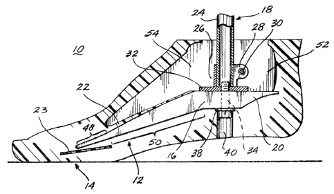
Referring initially to FIGURES 1-3, a prosthetic foot 10 includes a
cantilever spring keel 12 formed from viseoelastic material and encased in a
low-
density, foamed polymer cover or cosmesis 14 molded to resemble the shape of a
natural foot. The keel 12 includes a mounting or attachment flange 16 for
attachment of the prosthetic foot to an upper prosthesis 18. The keel also
includes a heel ledge 20 extending rearwardly from the mounting flange 16 and
a
singular, elongate forefoot portion or beam 22 cantilevered forwardly and
downwardly from the mounting flange. A load-distributing toe plate 23 is
located
closely beneath the front tip of the beam 22.
The prosthetic foot 10 is designed to permit the wearer to ambulate with a
substantially natural gait. To this end, during initial footfall, the heel
portion of
the cover disposed beneath the heel ledge 20 of the keel 12 is compressed to
allow
for a certain level of deflection of the cover. Thereafter, as the footfall
continues, a reaction loading is applied to the beam 22 which flexes in a
prescribed manner, initially relatively rapidly and then at a progressively
slower
rate to carry the weight of the amputee. During keel flexure, strain energy is
_ ~o ~ ~Z~o.
stored therein and then subsequently released in a timed spring-back or
restoration to impart an upward lift and forward thrust to the prosthetic
foot.
Next, describing the construction and operation of the foregoing invention in
greater detail, the keel mounting flange 16 is located longitudinally along
the
prosthetic foot 10 and elevationally low enough along the height of the
prosthetic
foot so that the foot is attachable to the upper prosthesis 18 at a location
substantially corresponding to the location of the ankle joint. The flat top
of the
mounting flange, located relatively low within the cover 14, permits the
prosthetic foot to be conveniently attached in a standard manner to the upper
r
prosthesis 18 which includes a standard prosthetic pylon 24 extending
downwardly
through a relatively large cavity 25 formed in the cover 14 above the mounting
flange and heel ledge. The bottom of the pylon is receivable within a standard
industry fitting 26, illustrated as being of the split-collar clamping type.
The
fitting 26 includes a clamping portion 28 surrounding the bottom of the pylon
24
and tightly clamped thereto by a clamping bolt 30. The fitting 26 also
includes a
base portion 32 that overlies the top of the mounting flange 16 of the keel.
An
attachment bolt 34 extends upwardly through a close-fitting clearance bore 36
formed in the keel mounting flange 16 to engage with a corresponding threaded
bore formed in fitting base 32. A flat washer 38 or similar hardware member is
positioned between the head of the bolt 34 and the bottom surface of the keel
mounting flange to distribute the compression load being applied to the keel
mounting flange by the bolt 34. A through bore 40 is formed in the cover 14
beneath the mounting flange 16 to provide clearance for the head of the bolt
34
and the washer 38 and to provide access to these components.
It will be appreciated that, by locating the keel mounting flange 16 at a low
elevation relative to the elevation of the keel forefoot beam 22, a smaller
bending
load is imposed on the attachment bolt 34 during use of the prosthetic foot
10,
than would occur if the bolt were positioned at a higher elevation relative to
the
bottom of the prosthetic foot. As a result, the likelihood that the bolt 34
would
fail from high bending loads or fatigue is reduced.
As shown most clearly in FIGURES 1 and 4, forwardly of the center of
bore 36, the sides of mounting flange 16 are parallel and correspond to the
sides of
the keel beam 22. Rearwardly of the center of bore 34, the sides of mounting
flange 16 taper to tangentially intersect the rounded rearward edge of the
heel
ledge 20. The tapered shape defined by the sides of the heel ledge, and the
adjacent sides of the mounting flange, of course, is to accommodate the shape
of
the heel portion oP the cover 14, which simulates the shape of the back of a
Zo ~ ~Z~o_
natural foot. The heel ledge 20 provides an upper support or abutment for the
heel portion of the cover, which is composed of resilient material that
compresses
during heel fall, i.e., as the bottom of the heel or the heel of the shoe, not
shown,
worn by the amputee, strikes the ground. It is to be understood that, in
addition
to utilizing resilient foamed polymer material, the other types of energy-
restoring
devices, such as compression springs, may be incorporated in the heel portion
of
the cover 14.
Additionally referring to FIGURES 2 and 3, the top surface of the heel
ledge 20 preferably is coplanar with the top of the mounting flange 16,
whereas
the bottom of the heel ledge tapers upwardly in the rearward direction.
Shaping
the underside of the heel ledge in a tapered profile permits more of the
resilient
heel material of the cover to be placed beneath the ledge than would be
possible if
the underside of the ledge were not tapered in the rearward direction. Forming
the heel ledge in this manner also reduces the weight of the prosthetic foot
in that
the material from which the keel is constructed, as discussed below, is
substantially denser than the material from which the cover 14 is composed. In
addition, it will be appreciated that the level of the bending stresses
imposed on
the heel ledge during heel fall decreases in the rearward direction, since the
moment arm component of the bending stress imposed on the heel ledge decreases
in this direction. This enables the thickness of the heel ledge to be
decreased in
the rearward direction without compromising the structural integrity of the
heel
ledge. The mounting flange 16 may include a bore 44 located rearwardly of the
bore 36 for attachment of the keel 12 to an upper prosthesis utilizing a
different
type of connection device, not shown, than described above.
The forefoot beam 22 of the keel 12 cantilevers diagonally downwardly and
forwardly from the mounting flange 16 to a location somewhat behind the
forward
tips of the toes formed in the cover 14. In plan view, the beam 22 is of
constant
width so that in transverse cross section, the beam is rectangular in shape.
Although in construction the beam 22 is a singular member, it is composed of
two
sections: a rearward, primary section 50; and, a forward section 48. In accor-
dance with one preferred embodiment of the present invention, the forward
section 48 composes approximately one-quarter of the length of the beam 22, so
that the primary section 50 composes approximately three-quarters of the
length
of the beam. Of course the relative lengths of the primary and forward
sections
may be altered in response to various factors, including, for example, the
total
length of the beam, the weight of the amputee, the maximum bending strength of
the beam, the desired dynamic characteristics of the keel, etc. As described
_
~..
Z0 1 42:50
_7_
below, the two sections of the beam 22 have different structural gnd physical
characteristics for desired load-carrying capacities, flexibility and other
dynamic
characteristics.
The primary section 50, as perhaps shown most clearly in FIGURES 2 and 3,
is tapered in the forward direction, having a straight bottom surface and a
parabolic-shaped top surface so that the capacity of the primary section to
carry
:. bending stresses is substantially constant along its length, but decreasing
slightly
in the forward direction. With this design parameter, if the keel were to
fail, it is
more likely that the failure would occur in the front portion of the primary
section rather than rearwardly, toward the mounting flange. This is important
in
that the ability of the prosthetic foot to continue to function during failure
decreases as the location of failure moves rearwardly along the keel length.
The
detrimental effect on the amputee of a keel failure is much less severe if it
occurs toward the forward section rather than if failure occurs close to the
mounting flange 16. The maximum thickness of the Keel oeam
cc ~s at ms
rearwardmost end, l.c., at its juncture with the mounting
flange 16, and is
s sufficient to enable the keel to safely carry a load
corresponding
to approximately
two and one-half times the body weight of the amputee.
The forward section 48 of the keel beam 22 is integrally
constructed with
and constitutes a continuation of the primary section 50.
Relative to the primary
section, the forward section is relatively thin and tapers
slightly in the forward
direction. Ideally, the bottom surface of the forward section
is straight and
coplanar with the bottom surface of the primary section 50.
The top surface of
the forward section 48 smoothly intersects with the top section
of the adjacent
portion of the primary section 50. In accordance with an
illustrative but not
limiting example of the present invention, the forward section
48 at its forward
end may be of a thickness of approximately one-fifth the
maximum thickness of
the primary section 50, with the thickness of the forward
section increasing
slightly in the rearward direction to smoothly transition
with the top of the
l
primary section so as not to create a discontinuity in the
keel beam 22. It will be
appreciated that, by constructing the forward section 48
in the foregoing manner,
the forward section exhibits significantly greater flexibility
relative to the
primary section when the beam 22 is initially loaded during
footfall. The
substantial compliance of the beam afforded by the forward
section enables the
prosthetic foot to closely simulate the "feel" of a natural
foot. Moreover, by the
foregoing construction, the structural integrity of the forward
section 48 is
sufficient to withstand the cyclical bending loads imposed
thereon during each
footfall.
.'r
- zo ~ ~2 ~o~.
By the foregoing construction of the keel 12 during footfall, the reaction
force F from the ground is initially applied to the tip of the cantilevered
beam 22,
causing deflection thereof, with the deflection first occurring in the forward
section 48, then progressively extending rearwardly to the primary section 50.
As
w 5 the deflection of the beam continues, the location at which the reaction
force F is
applied to the keel moves rearwardly along the beam, (see FIGURE 3),
eventually
to a location ideally about one-third of the length of the beam rearwardly
from
. the front tip thereof. It will be appreciated that, as the location at which
the
force F acts on the beam 22 moves rearwardly, the distance (designated as "D"
in
FIGURE 3) between the location of such force and the mounting flange 16
decreases, resulting in a corresponding decrease in the moment arm and, thus,
a
reduction in bending stress created by the reaction force. As a result, the
beam
may be configured to define a smaller section modulus than would be required
if
the reaction force F on the beam remained at the front end thereof, rather
than
shifting rearwardly in the manner of the present invention. This enables the
keel 12 to be constructed of a thickness that is thinner and/or of a width
that is
narrower than would otherwise be required to safely carry the weight of the
amputee.
The shifting of the location of the reaction force F rearwardly along the
beam 22 ideally occurs in a substantially continuous manner so that the beam
is
likewise flexed in a substantially continuous and gradual manner, thereby
facilitating the ability of an amputee to achieve a natural gait through the
use of
the prosthetic foot 10. To this end, preferably, the bottom surface of the
beam,
including the primary section 50 and the forward section 48, is shaped to
produce
a straight taper, rather than a parabolic taper therealong as employed on the
top
surface of the beam. It will be appreciated that, if the top and bottom
surfaces of
the beam 22 were reversed from that shown in FIGURES 2 and 3, a discontinuity
in the substantially continuous movement of the reaction force F rearwardly
along
the beam 22 would occur at the intersection of the forward section 48 and
primary
section 50 of the beam.
It will be appreciated that, as the location of application of the reaction
force F moves rearwardly along the tapered beam 22, the spring rate of the
keel 12 progressively increases. As an illustrative but not limiting example,
for a
keel having a beam approximately four inches long and approximately two inches
wide, the spring rate of the keel may increase by a factor of approximately
six
from a range of approximately 1001b/in to approximately 6001b/in. By this
increase in spring rate, the keel 12 of the present invention is capable of
carrying
t -.
_9_ ~4 ~ 42 ~t~...
a substantially greater load than would be possible iP the
spring rate did not
increase in this manner but instead remained substantially
constant. As a result,
by constructing the keel 12 in the foregoing manner, maximum
performance of the
keel is achieved per unit weight of the keel while also enabling
an amputee,
', 5 wearing the prosthetic foot 10, to closely achieve a natural
gait. As noted above,
' in prosthetic foot design, the minimization of weight is very
important.
Moreover, by constructing the keel 12 as described above,
the beam 22 need
not extend forwardly to the furthermost portion of the cover
14. As such, it is
possible to utilize the same keel 12 for several different
cover sizes corresponding
' 10 to at least three different foot sizes and to a relatively
wide range of amputee
weights, for example, a weight range of about fifty pounds.
Further, by the
foregoing construction, the size of the keel can be kept to
a minimum, which
contributes to the ability to position the mounting flange
of the keel relatively
low in the prosthetic foot, thereby allowing the prosthetic
foot to be joined to an
15 upper prosthesis at a location corresponding to the location
of an ankle joint of a
natural foot. As a consequence, the prosthetic foot 10 can
be utilized by
individuals who have had a Syme's amputation. Also, by positioning
the keel
mounting flange in this location, the prosthetic foot 10 can
be joined to an upper
' prosthesis with connection devices that enable the prosthetic
foot and the upper
20 prosthesis to be adjusted relative to each other in dorsal
flexion and plantar
flexion or with connection devices that simulate a natural
ankle joint, not shown.
To enable the keel l2 to achieve the foregoing advantageous
results,
preferably, it is constructed from a hardened polymer or polymers
capable of
withstanding the large stresses placed on the keel and also
the cyclical loading and
25 unloading that occur during normal use, while still minimizing
the weight of the
keel. The hardened polymer material should have a moderate
but not excessive
flexural modulus to enable the keel to sufficiently deflect
while withstanding high
stress and cycling levels. In addition, the hardened polymer
material used to form
t the keel should exhibit both elastic and viscous properties
so that deflection and
30 restoration of the keel under the cyclic loading of footfall
and footrise produces a
s timed or lagging stress versus yield relationship, thereby
to closely simulate the
action of a natural foot. One particular type of hardened
polymer material
exhibiting the foregoing properties is acetal homopolymer,
sold by DuPont
Corporation under the trademark DELRIN. Acetal homopolymer
exhibits a
35 flexural modulus of approximately 380,000 psi and has the
desired properties as
discussed above.
2014250_
-lo-
In constructing the keel 12 of the present invention, it will be appreciated
that reinforcing fibers can be utilized to strengthen the keel so that it can
be
formed from lighter weight polymers and/or formed in a smaller cross-sectional
size. However, care must be taken not to counteract the viscous properties of
the
hardened polymer which provides the desired dampening effect. Examples of
potentially useful high-strength fiber materials include carbon, aromatic
polyamides (for example, Kevlar from DuPont Corporation), and fiberglass.
.' Next describing the cover 14 in greater detail, preferably it is molded or
otherwise shaped to resemble the form of a natural foot. Ideally, the cover is
composed of a material capable of withstanding the many cycles of compression
loading imparted on the heel strike during footfall and also the flexing of
the keel
beam. In addition, the cover material must be able to withstand surface
abrasion
resulting from the various types of footwear that the amputee may choose to
wear. Also, importantly, the material from which the cover 14 is composed must
be compatible with the polymer material used to form the keel 12. In this
regard,
the cover material must bond to the exterior surface of the keel so that shear
loads acting at the interface of the keel and cover material are effectively
transmitted therebetween. A preferred cover material meeting the foregoing
requirements is a flexible, cellular polymer, for instance, polyurethane.
Ideally,
the material chosen and the production techniques utilized will result in a
relatively low-density cover in the range of from about fifteen to twenty-five
pounds per cubic foot.
As illustrated in FIGURES 2 and 3, the cover 14 is constructed with a rear
void or cavity 52 located in the portion of the cover above the heel ledge 20
of the
keel. A larger forward cavity 54 is located above the primary section 50 of
the
keel beam 22. The cavities 52 and 54 reduce the weight of the cover 14. It
will
be appreciated that constructing the keel 12 in the "low profile" described
above
and as illustrated in the drawings enables the cover 14 to be formed with the
weight saving cavities 52 and 54. In many prior prosthetic feet, the keel
occupies
a substantially greater portion of the interior of the cover than occupied by
keel 12 of the present invention. Applicant has found that, by constructing
the
keel 12 and the cover 14 in the manner described above, the weight of the
prosthetic foot 10 is approximately one-half of the weight of a comparable
size
prosthetic foot constructed in accordance with the above-mentioned U.S. Patent
No.4,645,509.
,.--- ..
_11_ 20 ~ 42 ~4...
Still referring primarily to FIGURES 2 and 3, a thin, substantially Plat and
rigid toe plate 23 is embedded in the forward portion of the cover 14 closely
below
x the forward tip of the keel beam 22. The toe plate 23 assists in
distributing the
downward load 48 imposed on the bottom of the cover by the forward section of
the keel beam 22 about a substantial area of the bottom of the cover. This
helps
prevent the cover from failing or otherwise being damaged by the shear
stresses
' and other stresses imposed thereon by the keel beam, especially when the
keel
,9
,beam is flexed during footfall. Preferably, the toe plate 23 is constructed
from
high strength but lightweight material(s), As an illustrative but nonlimiting
example, the toe plate 23 may be composed of urethane reinforced by polyethy-
lene fibers, for instance, Compet fibers from Allied Chemicals.
As will be apparent to those skilled in the art, the present invention may be
embodied in forms other than those specifically disclosed above without
departing
from the spirit or essential characteristics of the invention. The particular
~ 5 embodiment of the prosthetic foot 10, described above, is therefore to be
considered in all respects as being merely illustrative of a prosthetic foot
capable
of carrying out the present invention. The scope of the present invention is
as set
forth in the following claims, rather than being limited to the foregoing
description.