Note: Descriptions are shown in the official language in which they were submitted.
- ~o~ 9
FLUS~-MOUNTED ~TERFLOOR POWER/COMMUNICATION
CON~ECTION APPA~AT~S wIT~ DEBRIS PROTECTION
1 FIELD OF THE INVENTION
This invention relates generally to apparatus and
methods for the transmission of electrical power and
communication signals from one building floor to another and
pertains more particularly to so-called "poke-thru" devices
adapted for disposition in passages formed through concrete
floors.
BACKGROUND OF THE INVENTION
There has been extensive prior art activity in the
pursuit of averting the use of on-floor conduits for conveying
electrical power and communication lines to floor locations
which were not within the original architectural and electrical
planning of a facility, such as a multi-floor concrete
building. Such on-floor conduits are in the first place
aesthetically unpleasant and second}y can give rise to personnel
danger, such as by tripping over the same.
While the art has averted these problems in the
introdu~tion of flat undercarpet cable installations, the
problem remains extant in the use of the conventional discrete
wiring syste~s in place ~n general in existing buildings and for
currently-planned facilities for which the undercarpet approach
is not elected.
~ .
201441q
In the conventional discrete installations, the
problem under discussion has been addressed by drilling a
passage through the concrete floor and conducting power
and/or communication signals from a lower floor to the floor
in which a new power and/or communication signal outlet is
desired. Electrical safety codes have placed two sanctions
on such activity. Firstly, it is essential that the
installed transition apparatus not function as a chimney or
fire-advancing flue in the event of fire occurrence on the
lower floor. Secondly, it is imperative that the transition
apparatus not function as a conductive heat channel between
floors.
The industry has largely met these requirements
through the use of intumescent material in the transition
apparatus, such material expanding under fire conditions
against the concrete circumscribing the passage to
effectively block the pre-existing flue which may have been
present in the passage. Further, the art has reached
structures which have conductive heat blocking members, i.e.,
synthetic spacers, disposed axially between and separating
conductive heat communication between heat conductive members
of the apparatus.
Presently known transition apparatus can involve one
of two diverse types of pedestals, i.e., the flush-mount
pedestal and the low-profile pedestal, the latter protruding
upwardly of the floor to an extent and the former being
JJ:vs - 2
201a~19
1 essentially con~inuous with the f loor. The flush-mount pedestal
has a disadvantage as against the low profile pedestal in that
it is susceptible to entry of floor debris, such as dust,
moisture and the like. The art has seen various measures taken
protectively in this regard, such as sliding, swinging, threaded
or other mechanical me~bers to cover the pedestal face. Such
measures ha~e evident disadvantage in respect of increased cost
of manufacture of the installation and labor intensity in use.
SU~IARY OF THE INVENTION
The present invention has as its primary object the
provision of improved transition apparatus for interfloor
conveyance of electrical power and communication signals.
A particular object of the invention is to provide
interfloor electrical connection apparatus adapted for use with
flush-mounted pedestals and providing debris-resistant structure
therein at lessened cost and of lessened labor intensity in use.
In the attainment of these and other objects, the
invention looks particularly to an electrical connection housing
assembly for insertion in an interfloor passage for
floor-to-floor electrical transmission of both power and
comm-lnication, the housing assembly being adapted for receipt of
a flush-mounted pe~estal, and the invention provides such type
of assembly with debris-resistant structure not requiring
mechanical input thereto prior to electrical plug insertion
therein.
;~0~44~9
1 The housing assembly is addressed as background herein
and include~ a ~irst ~ousing comprised of first matter and a
second housing comprised of second matter of lesser heat
conductivity than the first matter. The second housing has a
first portion assembled with the first housing and a second
portion extending from the first housing. A power/comunication
divider unit is provided for separating respective power and
communication cables to be inserted in the assembly from one
another and the second housing defines keying for receipt of a
lo divider suited to a flush-mount pedestal.
The pedestal is applied to the housing assembly through
the use of a cover plate secured to the pedestal and a locating
bracket applied to the housing assembly. Per the invention
herein, a plate is secured to the cover plate and is situated on
a protective cover, which is a resilient membrane defining pads
in registry with power outlets of the pedestal and having at
least one peripheral pad for passage of the communication cable
therethrough.
The protective cover is composed such that it is
impermeable to dust and the like and functions as a barrier to
same entering the assembly,'but is penetrable to permit passage
of the comml~nication cable through such peripheral pad and to
likewise p~rnit passage of electical plug prongs therethrough
for connection in the pedestal outlets. Further, upon removal
f the cable and prongs the protective cover self-closes.
- 20~
1 ~he foregoing and other objects and features of the
invention will be further understood from the following detailed
description of preferred embodiments thereof and from the
drawings, wherein like reference numerals identify like parts
and components throughout.
BRIEF DESCRIPTION OF THE DRAWINGS
Fig. l is a perspective view of a partial connector
housing assembly in accordance with the invention disposed in a
concrete floor passage, the concrete being broken away for
purposes of illustration.
Fig. 2 is a front elevation of the lower housing of the
Fig. l assembly.
Fig. 3 is a rear elevation of the housing of Fig. 2.
Fig. 4 is a bottom plan view of the housing of Fig. 2.
Fig. 5 is a front elevation of the upper housing of the
Fig. l assembly.
Fig. 6 is a top plan view of the housing of Fig. 5.
Fig. 7 is a sectional view as would be seen from plane
VII-VII of Fig. 6.
Fig. 8 is a sectional view of the assembled lower and
upper housings as would be seen from the upper housing joinder
line 52 of Figs. 5 and 6.
- 2Q144~ 9
l Fig. 9 is a partial perspective view of the Fig. 1
assembly with a locating bracket applied thereto.
Fig. 10 is an exploded perspective view of the Fig. 9
assembly and a removable divider for insertion therein.
Fig. 11 is an exploded perspective view of a
flush-mount pedestal and a cover plate therefor.
Fig. 1~ LS a perspective view showing the pedestal and
cover plate of Fig. 11 applied to the assembly reached in Fig.
10 .
Fig. 13 is a top plan view of a generic embodiment and
usage of a protective cover assembly in accordance with the
invention.
Fig. 14 is a top plan view of the top plate of the Fig.
13 assembly.
Fig. 15 is a side elevation of the top plate of Fig.
14.
Fig. 16 is a top plan view of the protective cover of
the Fig. 13 assembly.
Fig. 17 is a bottom plan view of the protective cover
of the Fig. 13 assembly.
Fig. 18 is a sectional view of the protective cover of
the Fig. 13 as~e~bly as would ~e seen from plane XVIII-XVIII of
Fig. 17 on an e~arged scale.
2014419
DETATT~n DESCRIPTION OF PREFERRED EMBODIMENTS AND PRACTICES
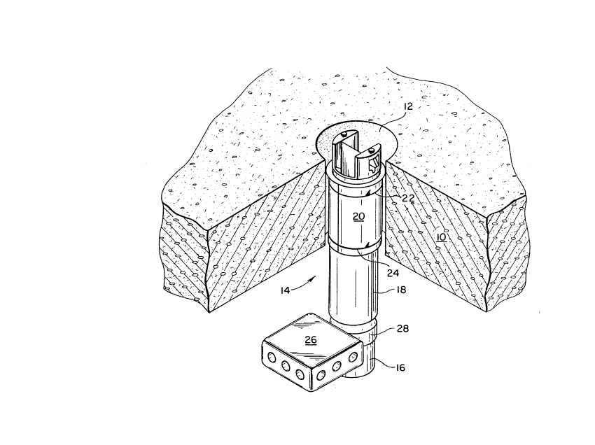
Referring to Fig. 1, concrete floor 10 has passage
12 formed therethrough and connector housing assembly 14
formed in part in accordance with the invention is disposed
in passage 12. Assembly 14 includes lower housing 16, upper
housing 18, intumescent material 20 wrapped about assembly
14 and secured thereto by wire straps 22 and 24. An
electrical connection box 26 is secured to lower housing 16
by strap 28, whereby electrical power and communication
signals on an underfloor may be advanced to an upper floor,
the cabling therefor not being shown in Fig. 1.
Turning to Figs. 2-4, lower housing 16 includes a
flat wall 30 which is comprised of electrically conductive
matter, such as a metal, and defines a ground connection
opening 32 and a fitting 34 for connection of a grounding
wire, e.g., wire 86 in Fig. 8.
Housing 16 has arcuate front wall 36 continuous with
flat wall 30 and defining therewith a channel for the receipt
of a communication cable. A lowermost opening 38 is formed
in front wall 36 for insertion of the communication cable.
Wall 30 has a top opening 44 bounded by tabs 40 on
its rearward side and by tabs 42 on its forward side for the
receipt and retention of separator or first divider 46 which
extends upwardly from wall 30 axially therewith to a free end
at which
JJ:vs - 7
20~4~9
1 divider 46 has mem~er 48 affixed thereto. Keys 42a and 42b are
formed on tabs 42 and keys 50a and 5Qb are formed on member 48
for purposes discussed below.
Figs. 5-7 depict the configuration of upper housing 18
of Fig. 1. In preferred form, ho~sing 18 is comprised of parts
18a and 18b, which are matable along mating line 52, each such
part being inclusive of a tail section 54 of open partial
semi-cylindrical configuration and a further section 56 of full
semi-cylindrical confuguration. Recesses are formed in section
56 as at 58 and 60 for cooperation with straps 24 and 22
respectively for securement of intumescent material 20 (Fig. 1).
Recess 62 supports the receipt of sealing ring 63 (Fig.
9). Upwardly of section 56, housing 18 has projections 64 and
66 which are in spaced and facing relation to one another.
Threaded openings 68 and 70 are formed respectively in
projections 64 and 66, as are slots 72 and 74. As is seen
particularly in Fig. 7, compartment 76 is recessed in the
sidewall of the housing sections for the receipt of a tumescent
material cylinder, also not shown. Fig. 7 also depicts lower
interior slot 78 formed in member 18a for purposes below
discussed.
Fig. 8 shows a sec~oned assembly of lower housing 16
and upper housing L8a, wherein divider 46 is shown in
positionally controlled position, defining channels or
20 1 44 1 q
compartments 80 on one side thereof and 82 on the other side
thereof. In this connection, key 42b and key 50b are
resident respectively in slots 78 and 72, key 42a is resident
in a slot counterpart to slot 78 in housing 18b and key 50a
is resident in slot 74 (Fig. 6). Arcuate section 84 is
formed in projection 64 to pass the communication cable upon
insertion thereof in compartment 80. Grounding wire 86,
affixed, typically by soldering, to member 34 extends through
compartment 82 exteriorly of assembly 14.
Turning to Fig. 9, in preparation of assembly 14 for
use with a flush-mount pedestal, locating bracket 88 is
applied to projections 64 and 66 by placing its dependent
arms 90 and 92 on the projections and securing the same in
place with fittings 94 and 96. A side channel 98 is formed
in projection 66, and also in projection 64 (not shown) for
constraining a securement nut against rotation for
cooperation with fittings 96 and 94.
Divider 100 (Fig. 10) is formed of sheet metal and
includes sidewalls 102 and 104 defining notches 102a and 104a
and floor 106a from which extends a tapered portion 106b, the
latter including keys 106c and 106d.
Prior to insertion of divider 100 in assembly 14,
putty 108 is used to fill the inside of the assembly, being
firmly placed about communication cable 110, grounding wire
86, and power conductors 112 and 114. Communication cable
110 is dressed through opening 84 as indicated. Divider 100
is now inserted into the assembly, keys 106c and 106d
entering slots 72 and 74 respectively, insertion continuing
JJ:vs g
201441q
until ends of arms 90 and 92 register with notches 102a and
104a.
Turning to Fig. 11, receptacle 116 has dual outlets
116a and 116b of customary three prong type. Cover plate 118
S is secured to receptacle 116 by screw 120 and includes
opening 122 for access to the outlets. Cross-arm 124
centrally spans opening 122 and includes side openings 126
and 128 and central opening 130 for passage of screw 120.
The completion of assembly 14 is depicted in Fig.
12, where plate 118 is shown secured in place by screws 132
and 134, which reside in openings 126 and 128 of cover plate
118 of Fig. 11. Plate 118 is situated on protective cover
136, which is a resilient member defining pads 138 and 140
in registry with outlets 116a and 116b and peripheral pads
142, 144, 146 and 148. Cover 136 is composed such that it
is impermeable to dust and the like and functions as a
barrier to the same entering the assembly, but is penetrable
to permit passage of communication cable 110 through one of
its peripheral pads, as shown at pad 142. Further, the
prongs of electrical plugs are insertable through pads 138
and 140 and, upon removal of the plugs, cover 136 self-
closes.
JJ:vs - 10
X ~
~Q~ 9
l The protective structure of the invention will be
understood in more detail by reference to the generic embodiment
and usage thereof shown in Figs. 13 through 18, to which
reference is now made.
Protective cover assembly 150 is shown in Fig. 13
applied to plate 152, which is disposed on a floor having an
opening in which flush-mount pedestal 154 is resident. Membrane
156, a resilient member which may be comprised of neoprene
rubber or polyurethane, is disposed on plate 152 and includes
outlet receptacle pads 158 and 160 and communication cable pads
162, 164, 166 and 168. Screws 170 and 172 secure cover plate
174 atop membrane 156 to pedestal 154.
Cover plate 174, which is rigid and comprised of metal,
is seen in Figs. 14 and 15 to have central openings 176 and 178
for passage of membrane pads 158 and 160 and perimetric slots
180, 182, 184 and and 186, extending radially inwardly of plate
174 for passage of pads 162-168 therethrough. Screw passage
openings 188 and 190 are counterbored.
In addition to its structure above discussed, membrane
156 is seen in Fig. 16 to have a flat surface 192 extending
intermediate its various pads for juxtaposition underneath cover
plate 174, a peripheral tapered portion 194 and screw passage
openings 196 a~d 1~8. Fig. 17 further indicates membrane 156 to
have a flat undersurface 200, outlet receptacle receiving
recesses 202 and 204 and communication cable receiving recesses
ZQ~4~
1 206, 208, 210 and 212, all such recesses extending upwardly from
undersurface 200 to the various pads of membrane 156.
As is illustrated, outlet receptacle pads 158 and 160
are formed with indentations at least in the upper surface of
membrane 156 in registration with plug prong receiving areas
thereof. Thus, for example, polarized prong receiving areas 214
and 216 of pad 158 have indentations 214a and 216a respectively
therein. Likewise, the communication cable pads of membrane 156
are formed with indentations in the lower surfaces thereof.
Thus, for example, pad 168 has a cross-indentation 168a formed
at its undersurface as is seen at recess 212 in Fig. 17.
Such indentations provide weakened areas of relatively
small thickness, facilitating penetrability of membrane 156 and
reclosure of the areas upon withdrawal of the penetrating
elements, which provides the membrane with a self-closure
capability.
The operative structure of membrane 156 is particularly
clear from the enlarged sectional view of Fig. 18. The membrane
has a preselected mAX;mum thickness in its dimension T1,
surrounding recess 202 and supporting pad 158. Polarized prong
receiving area 214 of pad 158 has a greatly reduced thickness
dimension T2 at ;n~entation 214~. Likewise, the communication
pads have a greatly reduced thickness, as is indicated by
dimension T3, shown for sectioned communication cable pad 162.
- ~01~4~9
1 ~alio~s changes may be introduced in the foregoing
apparatus and modifications may be made in the described
practices without departing from the invention. For example,
the protective apparatus of the invention will be seen to have
application to electrical plugs of configuration other than
those shown above. Accordingly, it is to be appreciated that
the particularly depicted and described embodiments and
practices are intended in an illustrative and not in a limiting
sense. The true spirit and scope of the invention are set forth
in the following claims.
,~