Note: Descriptions are shown in the official language in which they were submitted.
2~457~..
1-95,327
PNEUMATIC RADIA~ TIRES
HAVING IMPROVED RUNNING PERFORMANCES
This invention relates to pneumatic radial tires
having improved running performances.
Particularly, the improvement of the running
performances in this type of the tire are strongly
05 demanded in pneumatic radial tires for passenger cars
because it is required to always ensure a stable
steering property in the passenger car in accordance
with remarkable fullness of the equipments and
performances in the passenger car as well as the
enlargement and development of road networks.
In order to improve the running performances of
the pneumatic tire, it is necessary to have sufficient
rigidity in the tread portion and bead portion of the
tire. For this purpose, there are considered a counter-
measure of strengthening the reinforcement at the treadand bead portions, a countermeasure of raising an air
pressure filled in the inside of the tire, and the like.
However, the quantity of reinforcing member
required and used for the strengthening of the re-
inforcement is generally increased to undesirably raisethe cost. On the other hand, as the internal pressure
becomes higher, the ground contact area of the tread
portion reduces to obstruct the transmission of
2~45~
necessary force, and consequently the steering
performances, and traction and braking performances are
degraded.
That is, the tire should be used under such an
06 internal pressure as to hold a balance capable of
accepting merits through the strengthening of the
rigidity and demerits due to the degradation of the
performances. ~owever, the strengthening of the
rigidity without causing the increase of the cost can
not be achieved by the above conventional technique.
It is, therefore, an object of the invention to
provide a novel pneumatic radial tire for automobiles,
particularly passenger car which can advantageously
realize the reinforcement of tread and bead portions in
16 the tire without excessively using the reinforcing
member over the conventionally adopted limit and
increasing the internal pressure.
According to the invention, there is the
provision of a pneumatic radial tire having improved
ao running performances comprising a carcass composed of at
least one radial cord p].y toroidally extending between a
pair of bead portions as a casing reinforcement for
sidewall portions and tread portion connecting to the
bead portions, at least one cord ply of which carcass
2~ being wound around a bead core of the bead portion from
inside of the tire toward outside thereof to form a
Z~4157~
turnup structure, and a belt composed of plural cord
layers arranged along a crown portion of the carcass as
a tread reinforcement, charaGterized in that when the
tire is mounted onto a normal rim and inflated under an
0~ internal pressure corresponding to 5% of a normal
internal pressure, a carcass line of the carcass in
radial section of the tire at a self-posture under no
load has at least two inflection points between
positions A and C and/or between positions C and B in
which A is a position corresponding to each end of the
belt at its maximum width, B is a position corresponding
to a width of the normal rim and C is a position
corresponding to a maximum width of the carcass.
In a preferred embodiment of the invention,
heights Hl, H2 and M of the positions A, B and ~
measured from a rim base line of the normal rim are
within ranges of 0.80-l.0, O~lO-0.25 and 0.35-0.70 per a
carcass maximum height ~ measured from the same rim base
line, respectively.
20The invention will be described with reference
to the accompanying drawings, wherein:
Fig. :L is a schematic view illustrating the
carcass line according to the invention;
Fig. 2 is a diagrammatically sectional view of
the radial tire according to the invention;
Fig. 3 is a schematic view showing a deformation
-4-
~ 4~
behavior in the inflation under a normal internal
pressure;
Fig. 4 is a schematic view showing a comparison
of carcass profile used in the comparisons of Figs. 5
05 and 6;
Fig. 5 is a graph showing a comparison of
tension distribution in the belt between the tire accord-
ing to the invention and the conventional tire; and
Fig. 6 is a graph showing a comparison of
tension distribution in the carcass ply between the tire
according to the invention and the conventional tire.
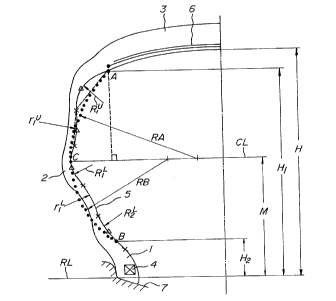
In Fig. l is shown a left-half section of the
pneumatic radial tire for passenger car according to the
invention in the radial direction thereof at a self-
posture under no load when the tire is mounted onto arim and inflate~ under an internal pressure correspond-
ing to 5% of a normal internal pressure. This tire is
symmetry with respect to the equator of the tire.
In Fig. l, numeral l is a bead portion, numeral
2 a sidewall portion, numeral 3 a tread portion, numeral
4 a bead core, numeral 5 a carcass, numeral 6 a belt and
numeral 7 a normal rim closely fitted into the bead
portion l.
The carcass 5 is comprised of at least one
2~ radial cord ply toroidally extending between the bead
portions l. In the illustrated embodiment, the carcass
2~aS~
is comprised of a single cord ply, but two or three
plies may be used. In any case, at least one cord ply
is wound around the bead core 4 from inside of the tire
toward outside thereof to form a turnup structure
0~ according to the usual manner.
In the above tire section at the self-posture
under no load, an intersect point of a perpendicular
line drawn from a widthwise end of a belt cord layer
having a maximum width in the belt 6 toward a rim base
line RL of the normal rim 7 with the carcass 5 is
defined as a position A, and an intersect point of a
perpendicular line drawn from the rim base line RL with
the carcass 5 at a position corresponding to an end of
the rim width of the normal rim 7 is defined as a
1~ position B, and a point corresponding to the maximum
width of the carcass 5 is defined as a position C.
Further, a straight line passing through the position C
and in parallel to the rim base line RL is CL, and a
radius of an arc having a center on the straight line CL
and passing through the positions A and C is RA, and a
radius of an arc having a center on the straight line CL
and passing through the positions B and C is RB.
Moreover, in the carcass 5 shown by a meandering curve,
a mark X is an inflection point of the carcass line and
2~ a mark ~ is a point most separated from a line segment
connecting the position A or B to the inflection point X
Z~14S7~
or a line segment connecting the adjoining inflection
points X to each other. Among arcs passing through the
position A or B, the inflection point or adjoining
inflection points and the point ~, a radius of an arc
having a center in the inner direction of the tire and
locating the point ~ toward the belt 6 with respect to
the straight line CL as a standard is represented by
R~ (i=l, ~-- nU), and a radius of an arc having a center
in the inner direction of the tire and locating the
point ~ toward the normal rim 7 with respect to the
straight line C~ as a standard is represented by RL
(i=1, ~-- NL), and a radius of an arc having a center in
the outer direction of the tire and locating the point
toward the belt 6 with respect to the straight line
CL as a standard is represented by rU. (i=l, ~-- mU), and
a radius of an arc having a center in the outer
direction of the tire and locating the point A toward
the normal rim 7 with respect to the straight line CL as
a standard is represented by rLi (i=1, mL).
According to the invention, the above radii are
preferable to be within ranges of the following
e~uations (1)-(4) in relation with the radii RA and RB,
respectively:
R,U
0.1 5 RA 5 0 7 (i= l, - - nU) ..... ( 1 )
5~
RL
0.1~; RB--0-7 (i=l, --n~1 ..... ( 2)
rU
0 3 ~; RA --1.0 (i=l, ---mU) ..... ( 3)
rL
0 3~5 RB c 1.0 (i=l,---mL) ..... ~4)
As mentioned above, the carcass line is adopted
to have at least two inflection points each of between
the positions A and C and between the positions 3 and C,
whereby the running performances of the tire can be
improved while using only the conventionally used
members without requiring new addition or change to the
structure of the tire as well as the reinforcing member
for the tread and bead portions~ so that the invention
has great merits in the quality and productivity of the
tire.
The aforementioned peculiar profile of the
carcass line is obtained by controlling a distribution
of rubber gauge ranging from an inner wall of a mold to
the carcass p].y in a rotational axis direction of the
tire in the building-up and vulcanization of the tire.
Moreover, if it is intended to strictly control
the change or scattering of the carcass line due to a
so-called "rubber flow" in the vulcanization, the
following method is particularly effective.
That is, the cord ply of the carcass 5 extending
2Q145~7~
between the bead cores ~ is merely arranged along the
inner shape of the tire according to the conventional
building-up and vulcanization method. On the other
hand, according to the invention, an inner liner 8
05 having locally different thickness portions 8' may be
used as shown in Fig. 2.
In addition, the change in the curvature of the
carcass line may properly be controlled by forming
continuous protrusions on a periphery of a bladder for
vulcanization at positions corresponding to curvature
changed portions of the carcass line.
By considering such a laborless means, the
carcass line according to the invention can properly be
controlled without causing the variation or scattering
in the productivity.
According to the invention, the carcass line of
the pneumatic radial tire in the radial section at the
self-posture under an internal pressure corresponding to
5% of a normal internal pressure has at least two
inflection points between the positions A and C and/or
between the positions B and C.
In Fig. 3 is shown carcass profiles having two
inflection points each of between the positions A and C
and between the positions B and C before and after the
inflation under a normal internal pressure, in which a
solid line is a carcass profile before the inflation and
2~ s~
dotted lines are a carcass profile after the inflation.
As to the deformation between the positions A and C, a
portion of the carcass line having a center of curvature
in an inside direction of the tire in adjacent to the
Off position A deforms inward the tire without changing the
curvature center, while a portion of the carcass line
having a center of curvature in an outside direction of
the tire deforms outward the tire with changing the
curvature center into the inside of the tire.
As to the deformation between the positions B
and C, a portion of the carcass line having a center of
curvature in an outside direction of the tire beneath
the position C deforms outward the tire with changing
the curvature center into the inside of the tire, while
16 a portion of the carcass line having a center of
curvature in an inside direction of the tire in adjacent
to the position A deforms inward the tire without
changing the curvature center.
The strain produced along the carcass line due
to the deformation of the tire is considered as follows.
In the portion wherein the curvature center
changes from the outside of the tire toward the inside
thereof, the carcass line has room against the
deformation of the tire before the inflation under
26 normal internal pressure, so that the strain produced
along the carcass line after the inflation under normal
- 10 -
~Q~ 5 ~
internal pressure becomes small, and consequently the
tension is small. Similarly, when the curvature center
of the carcass line is held inside the tire before and
after the inflation, if the carcass line is deformed
05 inward during the inflation under normal internal
pressure, the tension is small owing to the presence of
room against the deformation, while if the carcass line
is deformed outward during the inflation under normal
internal pressure, the tension becomes large to a
certain extent.
In the tension distribution between the
positions A and C, the carcass line adjoining to the
position A deforms inward with holding the curvature
center at the inside of the tire through the inflation
under normal internal pressure, so that the tension is
small. Further, the position of curvature center in the
carcass line located beneath the above carcass line
portion changes from the outside of the tire toward the
inside thereof, so that the tension is small.
That is, since the carcass tension near to the
widthwise end of the belt 6 is small, the belt tension
increases by a quantity that the carcass tension is
reduced from a balance between the internal pressure and
the sum of carcass tension and belt tension.
In the tension distribution between the
positions B and C, the curvature c~nter in the carcass
- 11 -
;~Q~
line located beneath the position C changes from the
outside of the tire toward the inside thereof through
the inflation under normal internal pressure, so that
the tension is small. On the other hand, the carcass
05 line located beneath the above carcass line portion
deforms outward with holding the curvature center at the
inside of the tire, 50 that the tension becomes not
small. Therefore, a portion of the carcass tension
reduced beneath the position C shifts to the lower
portion of the carcass line from a balance between the
internal pressure in the bead portion and the carcass
tension to more enhance the tension near to the bead
portion.
As a result, the tension is ununiformly
distributed through the carcass line, whereby large
tension can be given to each of the tread portion
requiring a large road gripping force and the bead
portion requiring a large transmission force to the rim,
and consequently the running performances are
considerably improved.
Moreover, in order to give most effective
tension to the tread and bead portions, the adequate
arrangement of radius of curvature of the carcass line
and position of inflection point or radii RUi (i=l,--- n~),
26 RL (i=l, nL), rUi (i=l, mU), and rLi (i=l,--- mL),
2~ i7~
per RA and RB as shown in Fig. l are favorable to be
within the following ranges, respectively:
RU
0.1~ RA :~ 0 7 (i=l~ nU)
RL
0.1< RB~07 G=l, nL~
rU
0 3 ~ RA ~ 1.0 (i=1, mU)
rL
03~ RBC1.0(i=l, mL)
Further, when the thickness of the inner liner 8
is locally changed as previously shown in FigO 2, it is
desirable that the portion 8' of Fig. 2 is 1.7 to
8 times, preferably 2 to 4 times higher than the average
thickness of the inner liner in order to sufficiently
suppress the change of the casing line.
The following example is given in illustration
of the invention and is not intended as limitation
thereof.
There was provided a passenger car tire (size:
165 SR13) comprising two steel cord belt layers and one
carcass cord ply as shown in Figs. l and 2 and having a
carcass line satisfying RU/RA=0.3, rU/RA=O.9, Rl/RB=0.3,
rl/RB=o.6~ and R2/RB=o.s5. ~hen, the actual running
test was made with respect to this tire together with
-13-
4S~
the conventional tire having a carcass profile of
natural equilibrium state. As a result, when the
running stability was evaluated by lO point method, it
was improved by l.5 point in the tire according to the
05 invention as compared with the conventional tire.
The profile of the carcass line in the tire
according to the invention and the conventional tire is
shown in Fig. 4, in which a solid line is a natural
equilibrium profile of the conventional tire before the
inflation under normal internal pressure and dotted
lines are the carcass profile of the invention before
the inflation under normal internal pressure.
Furthermore, the distribution of belt tension after the
inflation under normal internal pressure in the tire
16 according to the invention and the conventional tire is
shown in Fig. 5, while the distribution of carcass ply
tension after the inflation under normal internal
pressure in the tire according to the invention and the
conventional tire is shown in Fig. 6.
As mentioned above, according to the invention,
the belt rigidity and the bead rigidity of the tire can
advantageously be increased without enhancing the belt
and bead reinforcements or increasing the internal
pressure, which contributes to the improvement of the
running performance~ in the tire.
- 14-