Note: Descriptions are shown in the official language in which they were submitted.
MULTI-POSITION LATCHING MECHANISM FOR FORCEPS
FIELD OF THE INVENTION
The present invention relates to a latching mechanism for
a forceps-type surgical instrument and, more particularly,
to a multi-position latching mechanism for an aneurysm
clip applying forceps. The latching mechanism holds the
forceps jaws at various predetermined spacings to
facilitate the loading of clips into the jaws and the
placement of clips on the anatomy about the surgical
site.
BACKGROUND OF THE INVENTION
Forceps are used to place a variety of clips on the
anatomy during surgery. A variety of clips usually
hemostatic clips are applied with forceps. One type of
hemostatic clip of particular interest is an aneurysm
clip. One type of aneurysm clip is shown in U.S. Patent
~o. 4,777,950.
Hemostatic cl:;ps, including aneurysm clips, are applied to
blood vessels in various ways to close or strengthen a
blood vessel during or after surgery. The jaws of a
forceps are usually designed to receive a particular type
of clip. A clip is loaded into the jaws by the surgical
assistant and then handed to the surgeon who inserts the
clip into the surgical site.
To load a clip into the jaws the surgical assistant opens
the jaws and places the clip between the jaws manually and
then closes the jaws enough to hold the clip in place 50
that it will not fall out during insertion. It is,
however, important that the jaws not be closed too much so
COD-89
-2~ Q
as to start to open the clip since that might interfere
with the proper insertion of the clip.
One way of setting the jaws at a predetermined position is
to use two projections from the inside of each handle of
the forceps which overlap and interlock as is shown for
example in U.S. Patent No. 3,393,680. Although this is a
satisfactory lock for some applications, it is not
particularly well suited to applying an aneurysm clip. A
leaf spring e~tending between the insides of the two
opposing handles of the forceps is used to bias the
handles apart so that when the lock is disengaged the
forceps handles will open a predetermined amount thus
opening the jaws of the corresponding predetermined amount.
Another kind of forceps locking mechanism is shown in U.S.
Patent ~o. 4,462,404. This forceps locking mechanism can
be used to place the jaws at multiple positions. A leaf
sprinq attached to the inside of one forceps handle
extends across to the inside of the other forceps handle
and engages a complex latch which is affixed to the inside
of the opposing handle. Although this device works
satisfactorily, it is complicated and has variety of parts
which must be separately assembled to the forceps. Care
must be taken with this kind of latch mechanism to make
sure that it does not become damaged and misaligned during
cleaning and sterilization of the forceps.
It would be useful to have a latching device of simpler
design which could be used to set the jaws of the forcep
in a variety predetermined spaced apart positions so that
the surgical assistant could first load the clip into the
jaws and then firmly set the clip into position without
activating the clip. This would allow the surgical
assistant to quickly load the clip and hand the instrument
COD-89
_3_ 2~57~
to the surgeon who could easily insert the clip into the
surgical site. It would also be useful to have the latch
recycled to its initial position as the surgeon releases
his grasp on the forceps to further facilitate the loading
of the ne~t clip by the surgical assistant or
repositioning or removal of a clip just placed without
withdrawing the applier from the surgical site. Quick,
one hand recycling of the latch mechanism would be very
useful in repositioning or removing a clip.
SUMMARY OF THE INVENTION
The present invention relates to a latching mechanism for
a forceps type surgical instrument.
The forceps has first and second members, each having a
jaw disposed in opposing relationship on the distal end
portion and each having a handle disposed in opposin~
relationship on the pro~imal end portion. The members are
pivotably connected together so that as the handles are
closed toward one another, the jaws close toward one
another. The latching mechanism includes a first latch
portion extending from the first member with a resiliently
flexible free end and having an engaging surface. A
second latch portion on the second member includes a free
end adapted for engaging the engaging surface of the first
latch portion. The first latch portion free end and the
second latch portion are biased into engagement. A stop
formation, preferably a shelf, is formed on the first
latch portion engaging surface for receiving and holding
at least a portion of the free end of the second latch
portion when the handles are in a first predetermined
position. The latching mechanism includes a release for
moving the free end of the second latch portion out of
engagement with the engaging surface upon further closing
COD-89
7~
--4--
of the handles toward one another. There is also a means
for biasing the handles apart.
In the preferred embodiment, the second latch portion
includes a transverse e~tension adapted to engage the
engaging surface of the first latch portion.
The second latch portion transverse extension may include
a cross bar and connecting means connecting the cross bar
to the remainder of the second latch portion so that the
cross bar is spaced longitudinally at the free end of the
second latch portion.
The means for biasing the two handles apart may include an
extension from each latch portion extending proximally
beyond the pro~imal ends of the handles with the proximal
ends of the estensions are releaseably connected together.
Alternatively, the biasing means may extend distally from
the latch portions between the two members and may include
leaf springs which are releaseably connected together by a
slot and tab on the respective ends of the leaf springs.
The first latch portion engaging surface may include a cam
~5 surface for directing the free end of the second latch
portion and a step for holding the free end of the second
latch portion. The engaging surface may also include a
release, which in the preferred embodiment includes a slot
e~tending transversely into the side of the first latch
portion to receive at least a part of the free end of the
second latch portion so that as the handles move toward
one another, the free end of the second latch portion
moves into and through the slot.
C0~-89
2~57~.
--5--
The first and second latch portions are resiliently
flexible in the same plane of motion and the plane may be
oriented with respect to th~ plane of motion of the
handles at a variety of convenient angles.
In an alternative embodiment, the biasing means can be a
compression spring placed between the members of the
forceps to bias the handles apart.
The latch portions are preferably made of spring steel and
preferably attached to the pro~imal portion of the inside
of each handle.
As the latching mechanism moves among its various
positions, audi~le and tactile signals inform the user of
the operation of the latching mechanism.
These and other features and advantages of the present
invention will become more apparent from the following
detailed description of the preferred embodiment taken in
conjunction with the following drawings.
BRIEF DESCRIPTION OF THE DRAWINGS
Fi~ure 1 shows a side elevation of the forceps and
latching mechanism of the present invention with an
aneurysm clip placed in the jaws with phantom lines
indicating that as the jaws close the clip opens;
Figure 2 shows a partial perspective of the latching
mechanism;
Figure 3 shows a partial side elevation of the latching
mechanism;
COD-89
-6- 2~457~
Figure 4 is a partial end view of the latching mechanism
shown in Figure 3;
Figure 5 shows a partial side elevation of an alternative
embodiment of the invention; and,
Figure 6 shows a partial end view of the latching
mechanism shown in Figure 5 taken along line 6-6 in Figure
5.
DETAILED DESCRIPTION OF THE PREFERRED EMBODIMENTS
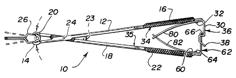
Referring now to Figure 1 there is shown a forceps 10
having a first member 12 with a jaw 14 on its distal end
and a handle 16 on its pro~imal end and a second member 18
with a jaw 20 on its distal end and a handle 22 on its
pro~imal end. Members 12 and 18 are pivotably connected
together at pivot point 24.
Jaws 14 and 20 are especially configured to hold an
aneurysm clip 26. First latch portion 30 is attached by
suitable means, preferably screw 32, to the inside 34 of
the distal portion of handle 16. Second latch portion 60
is attached by suitable means, preferably screw 64, to the
inside 35 of the distal portion of handle 22.
First and second latch portions 30 and 60 are preferably a
piece of flat spring steal but may be made in any
convenient shape or of any suitable resilient material so
that first and second latch portions 30 and 60 may be
flexibly resilient in the same plane and preferably in the
plane of motion of handles 16 and 22 (see Figure 1) or in
a plane perpendicular to the plane of motion of the
handles (see Figures 5 and 6).
COD-83
_7~ 457~
It will be noted that handles 16 and 22 may be offset from
the body of members 12 and 18 to form what is known in the
surgical instrument vernacular as a bayonet style forceps
such that the plane in which jaws 14 and 20 move is
laterally offset from the plane in which handles 16 and 22
move. This offset bayonet design is convenient for such
instruments but is not essential.
First latch portion 30 is preferably L-shaped with the
base 31 of the L attached to the proximal end of handle 16
and the shaft of the L including a specially configured
engaging s~rface 36 which projects toward handle 22.
Engaging surface 36 includes a cam surface 38 which is
shown in Figure 2 and is preferably a straight ramp at the
free end of first latch portion 30. Cam surface 38 of
engaging surface 36 can be any convenient shape so as to
engage ~nd deflect the confronting surface of second latch
portion 60 which will be explained later in the
application.
Engaging surface 36 also includes a shelf 40 which, in
this preferred embodiment, is generally at right angles to
the adjacent surface of first latch portion 30. Shelf 40
may form any convenient angle with the adjacent surface of
first latch portion 30 sufficient to hold the free end 62
of second portion 60 of the latch mechanism, and hence
handles 16 and 22~ in a first predetermined position.
Shelf 40 provides a formation for stopping free end 62 of
second latch portion 60.
A slot 42 extends into one side of engaging surface 36 of
first latch portion 30 and is located a predetermined
distance a~ove shelf 40. Slot 42 provides a means for
releasing the free end 62 of second latch portion 60 under
the resilient forces e~perienced by latch portions 30 and
COD-8~
-8- 2~7 4~7~
60 as handles 16 and 22 close toward one another from the
position where free end 62 of second latch portion 60
stops on shelf 40. 51Ot 42 can be on either side of first
latch portion 30 or may even be placed in the middle of
first latch portion 30 so long as free end 62 of second
latch portion 60 can be released from shelf 40 by passing
through slot 42.
Second latch portion 60 is affixed along the inside
surface 35 of member 18 preferably at the proximal portion
of handle 22 by means of screw 64. Second latch portion
60 is preferably L-shaped with the base 61 of the L being
attached to member'18 and the shaft of the L projecting
toward first latch portion 30. The free end 62 of second
latch portion 60 includes a transverse projection 66.
Transverse projection 66 may be any convenient shape but
is preferably an L-shaped projection e~tending from a
proximal portion 68 of second latch portion 60 with the
crossbar portion of the L-shaped projection corresponding
to transverse projection 66 and the shaft 70 of the
L-shaped projection e~tending from a pro~imal portion 68
of second latch portion 60. Transverse projection 66 may
extend from either side of second latch portion 60 and can
be at any convenient angle so long as it interacts
properly with cam surface 38 and shelf 40 of first latch
portion 30.
Transverse projection 66 need not be L-shaped but may be
any convenient shape so long as transverse projection 66
is held in a position that will permit it to interact with
engaging surface 36 and to easily enter shelf 40 and slot
42 when necessary. For e~ample, shaft 70 could be
C-shaped instead of straight or any other shape that
provides a convenient connection between transverse
COD-89
_9_ 2~457'~
projection 66 and proximal portion 68 of second latch
portion 60.
The handles 16 and 22 are biased apart preferably by means
of leaf spring projections 80 and 82 extending distally
from latch portions 30 and 60. Leaf springs 80 and 82 are /
preferably are made of spring steal and are made integral
with their corresponding latch portions 30 and 60. Leaf
spring 80 includes a slot 86 near its end and leaf spring
82 includes a tab 88 near its end. Slot 86 and tab 88
connect together to hold members 80 and 82 together to
provide a spring force to bias handles 16 and 22 apart a
predetermined amount. Alternatively, leaf springs 80 and
82 may extend pro~imally of handles 16 and 22.
Handles 16 and 22 could be biased apart by placing one or
/ more compression ~r torsion springs 23 between members 12
and 18 at any portion proximally of pivot point 24 but
preferably at a point close to pivot point 24 and also
preferably obscured by the pivot point of forceps 10.
The operation of the latch mechanism in the present
invention will now be described.
One can see from Figure 2 that leaf spring members 80 and
82 will bias handles 16 and 22 and, thus, jaws 14 and 20
apart a predetermined distance so that latch portions 30
and 60 are not in contact and so that the surgical
assistant can place aneurysm clip 26 within jaws 14,20.
The surgical assistant then proceeds to close handles 16
and 22 together to engage latch portions 30 and 60.
Referring now to Figure 3, one will see that as handles 16
and 22 are closed together transverse projection 66 of
second latch portion 60 is aligned to engage cam surface
38. The resiliency of latch portions 30 and 60 will cause
COD-89
- 1 o - ;2~57~ ~
one or both of latch portions 30 and 60 to deflect in a
plane generally parallel to the plane of motion of the
handles 16 and 22 causing transverse projection 66 to ride
along cam surface 38 and then further along engaging
surface 36 of first latch portion 30 until the resiliency
of latch portions 30 and 60 cause transverse projection 66
to move onto shelf 40. An audible and tactile signal will
~ c n,r ~o
be hcard when this occurs.
~ 3/~o/~9
with transverse projection 66 stopped on shelf 40,
aneurysm clîp 26 is firmly fixed in jaws 14 and 20 without
activating aneurysm clip 26. The surgical assistant may
then hand the forceps to the surgeon who inserts forceps
10 and aneurysm clip 26 into the surgical field. As the
surgeon further closes handles 16 and 22 together, the
jaws of clip 26 will open so they may encompass the
anatomy of interest. As the surgeon closes handles 16 and
22 further, transverse projection 66 will slide
resiliently further along engaging surface 36 above shelf
40 until transverse projection 66 is aligned with and
springs through slot 42. The resilient action ~f latch
portions 30 and 60 will then separate latch portions 30
and 60 so that leaf springs 80 and 82 may return handles
16 and 22 to their original position as the surgeon
relaxes his gxip to open jaws 14 and 20 and set clip 26 on
the anatomy of interest.
Those skilled in the art will recognize that the initial
spacing of the jaws can be properly controlled by
adjusting leaf spring members 80 and 82. This is
important because these parts can become bent and
misaligned during cleaning and sterilization, but it is
easy to re-align them to allow the latch mechanism to work
properly.
~OD-89
-11- 2~S7~
If, after setting clip 26, the surgeon wishes to
reposition or even withdraw it, he can easily do so
without removing forceps 10 from the incision. Open jaws
14 and 20 can be placed about clip 26 and closed until
transverse projection 66 engages shelf 40 indicating to
the surgeon that clip 26 is secured in jaws 14 and 20.
The surgeon then closes handles 16 and 20 to open jaws of
clip 26 for repositioning. If the surgeon wishes to
completely remove clip 26, one may follow the above steps
for repositioning and continue by withdrawing jaws of clip
2b away from the anatomy about which they were
positioned. One then closes handles 16, lB further to
thus recycle transverse projection 66 through slot 42 and
then rela~es one's grip to close clips 26. One then
partially closes handles 16 and 18 to engage transverse
projection 66 on shelf 40. The surgeon, knowing that clip
26 is firmly held in jaws 14, 20 and that clip 26 is
closed, can withdraw clip 26 with its jaws closed so as to
avoid damage to the surrounding anatomy during withdrawal.
Referring now to Figures 5 and 6 there is shown an
alternative e~bodiment of the present invention. First
latch portion 130 is attached to the distal portion of
handle 16 and e~tends toward handle 18 and includes an
engaging surface 136 including a cam surface 138, a shelf
140, a plurality of retaining steps 141 and a slot 142.
Second latch portion 160 is attached to a pro~imal portion
of handle 18 and extends toward handle 16 and includes a
generally L-shaped portion having a shaft 170 and a
transverse projection 166.
First and second latch portions 130 and 160 are made of
spring steel and are resiliently flexible in the same
plane, which in the embodiment of Figures 5 and 6, is
COD-89
~457~
-12-
shown perpendicular to the plane of motion of handles 16
and 18. The plane of resilient flexibility of latch
portions 130 and 160 can be set at any convenient angle to
the plane of motion o~ handles 16 and 18 by rotating latch
portions 130 and 160 about their attachment screws 32 and
64.
Handles 16 and 18 are held in a first predetermined
position by leaf springs similar to leaf springs 80 and 82
of the embodiment shown in Figure 1 or by means of a
compression spring 23 like that shown in Figure 1.
The operation of this embodiment will now be explained.
With handles 16 and 18 separated under the influence of
the biasing springs (not shown) the surgical assistant can
insert an aneurysm clip 26 in the jaws of the forceps as
was done with the embodiment of Figure 1. The surgical
assistant then closes handles 16 and 18 together so that
transverse projection 166 contacts cam surface 138
20 deflecting latch portions 130 and 160 as the contact
continues. Transverse projection 166 will engage shelf
140 as the closing of handles 16 and 18 continues. The
surgical assistant may then hand the forceps to the
surgeon knowing that clip 26 is firmly held in the jaws of
the forceps. The variety of steps 141 are provided so
that a number of fi~ed positions of the latch mechanism
and correspondingly of the forceps jaws may be set. As
the surgeon further closes handles 16 and 18 together
trans~erse projection 166 will travel toward and then
spring thrGugh slot 142 under the influence of the
resilient flexibility of latch portions 130 and 160, thus
releasing the latch mechanism and allowing the surgeon to
release his grip on handles 16 and 18 to recycle the
latch.
COD-89
-13- 2~ ~57.~
The present invention has been described in conjunction
with the preferred embodiments. Those skilled in the art
will appreciate that many modifications and changes may be
made to the preferred embodiments without departing from
the present invention. It is, therefore, not intended to
limit the present invention except to set forth in the
appended claims.
COD-89