Note: Descriptions are shown in the official language in which they were submitted.
-~,
BACKGROUND OF THE INVENTION ~ 7
The present invention relates to writing pens, and
more particularly, to ball-point pens.
Pens come in a variety of shapes, sizes and types.
There are felt tip pens, ball-point pens and fountain pens,
all of which employ an ink reservoir mated to a writing tip
of some sort and a body or housing for containing the
writing tip and reservoir. For ball-point pens, the writing
tip includes a ball contained in a metallic or plastic tube
to form a ball-point. In use, the ball-point is rubbed
against the surface of the paper and ink flowing from the
reservoir to the ball-poin-t is neatly deposi-ted on the
surface of the paper.
In order to maximize the free flow of ink onto
paper, the body of the pen should be held so that the
ball-point is held as close to a vertical position from the
surface of the paper as possible. If the ball-point is not
held at such a steep angle, the ball-point lays down less
ink on the paper.
Traditionally, pens have had straight tubular
housings or bodies for containing the ink reservoir, which
have an apertured writing end through which the writing tip
projects in order to make contact wi-th the paper. The
, ,
;~ 73~
straight tubular nature of traditional pen bodies is
adequate for retaining the writing tip and ink reservoir but
does not maximize the comfortable use of the pen.
In -the past, attempts were made to improve the
comfortable use o-f pens by modifying the housing with ridges
or bulges located near the writing tip in order to better
conform the housing of the pen to the grip of the user.
Other attempts included the use of customized or modified
writing tips in order to improve the position of the writing
tip in rela-tion to the grip of the user. H.R. Fehling e-t
al., U.S. Patent No. 3,106,190 discloses a ball-point pen
having a ball held within an angled metal tube. This angled
tube permits -the ball-point to be held at the axis of the
housing and at an angle closer to -the verticle when the body
of the pen is held in a comfortable writing position.
Although a custom writing unit having a angled ball-point
makes for better contact of ball-point with paper, the
comfortable grip of the Fehling pen as with previous pens is
limited by the straight stick-like shape of the body.
SUMMARY OF THE INVENTION
The present invention overcomes at least some of
the limitations of the prior ar-t by providing a pen having a
tubular housing with an aper-ture at one end thereof, a long
' .
:`
-- 2
~ .
,
.
~473~
tubular flexible reservoir dimensioned -to fit within the
housing, a writing tip mated to the ink reservoir and
dimensioned to fit through the housing aperture, wherein a
lower sec-tion of the housing adjacent the apertured end is
shaped to reposition the writing tip relative to -the
longitudinal axis of an upper substantially straight section
of the housing. The shaping of the lower section takes the
form of a first por-tion extending away from the longitudinal
axis at a first angle and having a first pre-selected length
and a second portion contiguous with the first portion
having a second pre-selected length and extending back
towards the longitudinal axis at a second angle rela-tive -to
the first portion. The first and second pre-seleted lengths
and the first and second angles are selected to position the
writing tip at a pre-selected distance from the longitudinal
axis.
In an alternative embodiment of the invention, the
first and second portions are not co-planar and the angle of
the second por-tion is selected to further position the
writing tip at a third angle relative to the longitudinal
axis and to one side of the plane of the housing defined by
the first portion and the upper straight section of the
housing.
Other features and advantages of the present
invention will become apparent from the following detailed
-
.
~.
3~3
""~ .
description, taken in conjunc-tion with the accompanying
drawings, which illustrate, by way of example, the
principles of the invention.
BRIEF DESCRIPTION OF THE DRAWINGS
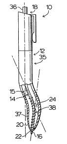
Figure 1 is a side elevational view of a preferred
embodiment of -the invention showing the writing tip in the
extended position.
Figure 2 is a side elevational view of the
preferred embodiment, partly broken away in cross-section
showir.g the ink reservoir and writing tip.
Figure 3 is a front elevational view of the
preferred embodiment, showing the writing tip in the
extended position.
- Figure 4 is a front elevational view of an
alternative embodiment showing the writing tip in the
extended postion.
Figure 5 is a front elevational view of another
alternative embodiment showing the writing tip in the
~extended postion.
.
~ - 4 -
:- : :~. :
.
3~3
DETAILED DESCRIPTION OF THE PREFERRED EMBODIMENTS
As can be seen from Figures 1 and 2, the pen shown
generally as 10 comprises housing shown generally as 12, ink
reservoir means shown generally as 14, writing tip shown
generally as 16, and retracting means shown generally as 18.
With particular reference to Figure 2, ink
reservoir means 14 comprises a long tubular flexible ink
reservoir 15 which is mated to writing tip 16. Ink
reservoir 15 is a long flexible tube which is easily bent
and deformed. In a' preferred embodiment, wri-ting tip 16
comprises a ball-point writing tip. Housing 12 is a long
tube-like structure which tapers to writing end 20 having
aperture 22. Housing 12 has chamber 24 and flexible ink
reservoir 15 is adapted to fit within chamber 24. Writing
tip 16 is configured to project through aperture 22.
Retracting means shown generally as 18 preferably
comprises a push button 36 which engages reservoir 15 which
in turn is blased by spring 38. When push button 36 is
depressed, reservoir 15 is pushed down through chamber 24
and writing tip 16 is extended out of aperture 22. A
mechanism is provided within housing 12 for holding the
reservoir in this position when push but-ton 36 is released.
Such mechanisms are:well known in the art and may comprise a
:
thrust tube/rotating sleeve arrangement, a ball and cam
- 5 -
!
:
~ :,
,~
.:
:
7~
mechanism or some other mechanism. Which ever mechanism is
used, when push button 36 is depressed and released again
writing point 16 is drawn into chamber 2~ by the recoil
action of biasing spring 38. In order to facilitate the
manufacture of these retractable pens, housing 12 is formed
in two pieces which can be separa-ted to permit the replacing
of reservoir 15 when the ink contained therein is exhausted.
Referring to Figure 1, housing 12 has an upper
straight section 26 having a longitudinal axis shown by
dotted line A. Lower section 28 of housing 12 ad~acent
apertured 22 is shaped to reposition wri-ting tip 16 relative
to longi-tudinal axis A. Lower shaped section 28 comprises
first portion 30 and second portion 32. Firs-t portion 30 is
continguous with upper straight sec-tion 26 and has an axis
of its own defined by dot-ted line B. First portion 30
extends away from longitudinal axis A a-t first angle R.
Second portion 32 is contiguous with first portion 30 and
has also an axis of its own as shown by dotted line C.
Second portion 32 extends back towards -the longitudinal axis
A at second angle S relative to axis B. First portion 30
and second portion 32 have a first pre-selected length and a
second pre-selected length respectively. The first and
second pre-selected lengths and angles R and S are selected
to position writing tip 16 at pre-selected distance 34 from
longitudinal axis A. In the preferred embodiment, axes A, B
and C are co-planar, and angle S is selected so that axis C
-- 6
~ .
; ~
'
.
73~
intersec-ts axis A at -third angle T resulting in writing tip
16 being positioned at third angle T relative to
longitudinal axis A.
Preferably, first angle R is between 15 to 30,
second angle S is between 10 to 30, third angle T is
between 5 to 15, the lengths of first portion 30 and
second por-tion 32 are between 2 -to 4 cm and 1 to 3 cm
respectively, the ]ength of first portion 30 being greater
than second portion 32. In the preferred embodiment, R is
about 12, S is about 20 and T is about 8.
As shown in Figure 3, in a preferred embodiment,
the bending of the lower section 28 of pen 10 -takes place in
a single plane, i.e. axes A, B and C are in a single plane.
However, as shown in Figure 4, in an alternative ,
"right handed" embodiment, shown generally as 40, second
portion 42 of lower housing section 44 is bent relative to
- first portion 41, resulting in axis C1 of second portion 42
not being in the plane defined by first portion 41 and upper
stright housing section 48, such plane extending out of the
page towards the reader. This bending of lower portion 42
results in writing tip 47 being positioned at angle V
relative to the longitudinal axis A at a distance of
between about 1 to about 3 mm from the aforesaid~plane.
This alternative embodiment would be particularly useful as
:
- 7 - -
~ - \
a writing implement for right handed people because it
posltions -the writing tip towards the user and therefore the
user can better see the writing tip and also results in less
hand strain.
Referring now to Figure 5, in yet another
alternative embodiment of -the invention shown generally as
50, second portion 52 angles away from first portion 51 so
that the axis of second portion 52 as shown by dotted line E
intersects the plane defined by upper housing section 58 and
first portion 51 of lower housing section 54 at angle W as
shown in Figure 5. This alternative embodiment would be
particularly useful for people who are left handed.
In opera-tion, the writing tip is first extended
out of aperture 22 by depressing push button 36. Housing 14
is then grasped such that the thumb of operater rests
agains-t the point 35 near the junction of longitudinal
portion 26 and first portion 30 and the third finger of the
same hand rests against point 37 near writing end 20 of pen
10. Because writing tip 16 is positioned a-t pre-selected
distance 34 from longltudinal axis A, and at third angle T
relative to longitudinal axis A, pen 10 can be held
comortably in the hands, while at the same time positionlng
writing tip 16 at an angle which is steeper than the angle
between the paper and the longitudinal axis of the upper
part of the pen housing.
~ ~: : . , ,, ~
This positioning of writing tip 16 facilitates the
free flow of ink, particularly if writing tip 16 comprises a
ball-point. Furthermore, because of the shape of first
portion 30 and second portion 32 of lower section 28,
flexible ink reservoir 14 can slide rreely within chamber
2~, and therefore housing 12 could be utilized wi-th standard
flexible ink reservoirs having standard ball-points mated
thereto. Also, because of the shape of housing l~ and the
resulting orientation of the thumb and third finger when the
pen is held in a writting position, the pen is more
comfor-table to hold. The lessening of the strain together
with the generally more comfortable grip associated with pen
10 makes the use of pen 10 more comfortable in the hands of
operators suffering from ar-thritis of the hands.
Although a retractable ball-point pen is
illustrated in Figures 1 through 5, it is clear that the
present invention may also comprise non-retractable pens
having one piece or two piece bodies which use ball-point or
felt tipped writing tips. In embodiments where no
retracting means is provided, the writing tip is rigidly
retained by the housing such that it rigidly extends out
through the aperture. A cover or cap may be provided -to
cover over the writing tip when the pen is not in use.
Furthermore, all of the angles and pre-selected
length may be modified to bet-ter conform the shape of the
g
~ ~ . - ,. ~ ."
.: - : . :
. : . : ' : ' ' ~ : .
~ ~ .
.
:
lower section of the housing to children.
~ he invention has been described with reference to
the preferred embodiment as well as some alternative
embodiments. However, it is clear that certain
modifica-tions and variations can be made to the above
embodiments without departing from the invention and such
modifications and variations are intended -to be included as
falling within -the scope of the following claims.
- 1 0
~ '
: ~ " ' : ~ ', :
.
,
-