Note: Descriptions are shown in the official language in which they were submitted.
TAPPING ATTACHMENT FOR A PUNCH PRESS
TECHNICAL FIELD
This invention relates to a tapping
attachment, cuhereby an axially directed force
generated by a turret-type punch press is
converted into a rotating force .for advancing and
turning a tap, so that an array of holes may be
efficiently and inexpensively threaded through a
sheet metal part, or the like.
~~~.~'7~: ~_
BACKGROUND ART
A drill press and an associated tapping unit
are typically used to tap holes formed in a sheet
metal part. However, a drill press is known to be
slow, labor intensive ands thereby cost
inefficient, Moreover, a drill press is used
merely to drill and not thread holes. Therefore,
the metal part is subject to multiple handling
stages and to separate operational steps of
drilling and then threading holes.
Tapping attachments have been used in the past
with conventional punch-type presses for tapping
holes formed in metal parts. However, and
generally speaking, such attachments are
characterized by a large size, thereby rendering
them cumbersome and not suitable for use with a
numerically controlled punch press. The
conventional tapping attachments are also known to
include a transmission that, because of its high
torque requirements, is often characterized by a
complex gearing arrangement and a corresponding
large size. Such a large size usually requires
that the tapping unit be securely bolted onto the
~~~~.~-~i ;,~
punch press. Consequently, there is no way by
which the tapping unit may be easily detached from
its press for repair or replacement.
It would be preferable to have available an
efficient tapping unit that has a simple
transmission and no gears, is of small size and
relatively low cost, and is easily attachable to a
numerically controlled turret-type punch press or
the like so that holes can be punched and threaded
through a sheet metal part with minimal handling
and in an efficient and cost saving manner.
4
SUMMARY OF THE INVENTION
zn general terms, a relatively light weight,
low cost tapping attachment is described to be
interfaced with a turret-type punch press, or the
like, so as to control an associated tap for
rapidly threading holes formed in a sheet metal
workpiece at a low cost per hole. The tapping
attachment includes a thrust bearing surface which
is movable linearly, in response to an axial force
generated by the punch press, from a first, at
rest, position to a second, loaded position. As
the bearing surface moves from the first to the
second position, a set of pistons are
correspondingly moved downwardly through respective
cylinders formed in a valve body. Nitrogen gas,
which is supplied from a gas reservoir to the
cylinders so as to be compressed therein during the
down stroke, expands to drive the pistons upwardly
through their cylinders to thereby return the
thrust bearing surface to the first position at
which to receive another axial force generated by
the punch press. Cutting oil is supplied from an
oil reservoir to the tap to periodically lubricate
and cool the tap during the threading operation.
~~~_~'~c~ ~~.
A gearless transmission is provided to convert
the linear movement of the thrust bearing surface
into both linear and rotary movements of the tap.
More particularly, a spline shaft having a
multi-start, screw threaded end and an opposite
spline threaded end is connected to and movable
with the bearing surface. The screw threaded end
of the spline shaft is moved axially through a
roller nut, whereby to cause the spline shaft to
rotate. The linear movement and rotation of the
spline shaft is imparted to the tap by way of a
spline nut and a lead screw. The lead screw has a
threaded shaft which rotates in and moves axially
through a stationary lead nut. The tap is
interconnected by a collet with the lead screw
shaft to that the tap is rotated and moved with
said shaft. Accordingly, the tap is advanced to
and rotated within the hole of the workpiece,
However, by making the thread pitch of the tap and
lead screw shaft smaller than the thread pitch of
the threaded end of the spline shaft, the tap is
advanced a smaller distance than the linear
distance traveled by the spline shaft through the
roller nut.
s
BRIEF DESCRIPTION OF THE DRAWINGS
FIG. 1 is a perspective view of the tapping
attachment which forms the present invention;
FIG. 2 shows the interconnection of a thrust
bearing assembly and a valve body of the tapping
attachment of FIG. 1;
FIG. 3 is an exploded view of the thrust
bearing assembly of FIG. 2;
FIG. 4 shows the detachable interconnection of
the valve body and a transmission housing of the
tapping attachment;
FIG. ~a shows an enlarged view of a
commercially available roller nut which is located
between the valve body and transmission housing of
FIG. 4;
FIG. 5 is an exploded view of the transmission
housing of FIG. 4;
FIG. 5a is a cross section showing an oil pump
piston being retained at an oil pump actuator of
the transmission housing of FIG. 5;
FIG. 6 is a still further exploded view of the
transmission housing;
FIG. 7 is a partial cross-section of the
tapping unit in a relaxed configuration; and
FIG. 8 is a partial cross-section of the
tapping unit in a loaded configuration in response
to an axially directed force generated by a punch
press.
s
DESCRIPTION OF THE PREFERRED EMBODIMENT
The tapping attachment 1 which forms the
present invention and which is capable of rotating
a tap at very high speeds (e.g. 10,090 RQM) is
described while referring to the drawings, where
FIG. 1 illustrates the interconnection of a tapping
head assembly 2 with a reservoir assembly 4. The
tapping attachment 1 may be interfaced with a
conventional numerically controlled, turret-type
punch press (not shown) so that an axially directed
force generated by the press can be effectively
converted into a rotary force for turning the tap
at high speeds. The tapping head assembly 2
includes a thrust bearing assembly 6 which provides
a bearing surface to receive the axially directed
force generated by the punch press. As will be
described in greater detail when referring to FIG.
3, thrust bearing assembly 6 includes a pair of
thrust bearings which minimize friction with and
receive the axial force generated by the punch
press.
The tapping head assembly 2 of tapping
attachment 1 includes an upper valve body 8 and a
lower transmission housing 10. Valve body 8 (which
~~''~~'~(""
9
is described in detail when referring to FIG. 4)
includes the aforementioned thrust bearing assembly
6 that is initially spaced above the valve body
(best shown in FIG. 7) and aligned for engagement
by the punch press, so that the bearing assembly
can be pushed downwardly towards the valve body $
(as shown in FIG. 8) in response to an axial
driving force. As will also be described, a supply
of nitrogen gas is provided from a nitrogen
reservoir 14 of reservoir assembly 4 to valve body
$ to drive the thrust bearing assembly 6 upwardly
so as to return to its initial, spaced position
relative to valve body $ so as to be ready to
receive another axial force generated by the punch
press. Thus, it may be appreciated that bearing
assembly 6 reciprocates relative to valve body 8
for the important purpose of transferring the axial
force generated by the punch press to a rotary
force for turning a tap by way of the transmission
housing 10.
Transmission housing 10 includes means (which
are described in greater detail when referring to
FIGs. 5 and 6) for converting the axial movement of
the bearing assembly 6 into a rotary movement of
the tap. An axially extending keyway 16 is formed
10
in the transmission housing 10 to align the
tapping attachment 1 for connection to the punch
press so as to prevent rotation of the tapping
attachment relative to the press. An oil spout
(designated 78 in FIG. 4) projects outwardly ~rom
an oil spout slot (best shown in FIG. 4) to supply
lubricating oil to the tap.
The reservoir assembly 4 of tapping attachment
1 includes an upper cutting oil reservoir 12 and a
lower nitrogen reservoir 14. A filler cap 18 is
associated with oil reservoir 12 so that said
reservoir can be loaded with oil. Similarly, a
filler tube 20 is associated with reservoir 14 so
that said reservoir can be filled with nitrogen
gas.
Referring now to FIGS. 2 and 3 of drawings,
the details of the thrust bearing assembly 6 of
tapping attachment 1 are disclosed. Referring
first to FIG. 2, the thrust bearing assembly 6 is
shown having a plurality of (e.g. four) holes 22
through which a corresponding plurality of socket
head cap screws 24 are to be received. projecting
outwardly from bearing assembly 6 (for receipt
within the valve body 8 and transmission housing 10
~~_~': ~~'
11
of head assembly 2? is a spline shaft 26 having a
multi-start threaded end 28 and an opposite spline
end 3H. The threaded end 28 of the spline shaft 26
includes four continuous screw threads extending
therearound.
A set of (e.g. four) pistons 32 (only two of
which are visible in FIG. 2) are received within
respective cylinders of the valve body 8 (best
shown in FIG. 4). such that top ends of said
pistons 32 project outwardly from the valve body 8
for receipt within respective holes 22 in bearing
assembly 6 to be mated therein with screws 24. In
the assembled relationship, each cap screw 24 is
attached to a corresponding piston 32 within a
respective hole 22 of the bearing assembly 6. In
this manner, when the thrust bearing assembly 6 is
moved downwardly towards valve body 8 in response
to an axial force generated by the punch press, the
cap screws 24 thereof are, likewise, moved
downwardly, whereby to correspondingly push the
pistons 32 into the valve body.
In FIG. 3, the thrust bearing assembly 6 is
shown in an exploded configuration, with top and
bottom bearing housings 36 and 38 released and
12 ..
separated from one another. That is, the top
housing 36 has a locking lip 40, and the bottom
housing 38 has a locking flange 42. In the
assembled configuration (of FIG. 2), locking flange
42 is sized to be rotated below the locking lip 40
by which to releasably secure the top and bottom
bearing housings 36 and 38 together.
As was earlier indicated, the thrust bearing
assembly 6 includes a pair of thrust bearings.
More particularly, bearing assembly 6 includes
upper and lower thrust assemblies Q4 and 46. Upper
thrust assembly 44 includes a first thrust
bearing 48 which is surrounded by top and bottom
thrust washers 50 and 52. Similarly, lower thrust
assembly 46 includes a second thrust bearing 54
which is also surrounded by top and bottom thrust
washers 56 and 58. The upper thrust assembly 44 is
sized to be received against a region 45 of the top
housing 36 so as to be axially aligned with the
punch press. The lower thrust assembly 46 is sized
to be located above an opening 47 in the bottom
housing 38, such that upper and lower thrust
assemblies 44 and 46 and openings 45 and 47 are
concentrically arranged relative to one another
through the thrust bearing assembly 6.
~~~,,~ ~ s -~~
13
The previously described spline shaft 26 is
connected at its threaded end 28 to a thrust flange
60 which, in the assembled configuration, is
supported between the bottom thrust washer 52 of
upper thrust assembly 44 and the top thrust
washer 56 of lower thrust assembly 46. Thus, the
thrust flange 60 of spline shaft 26 will be located
between the openings 45 and 47 of top and bottom
housings 36 and 38. Moreover, the threaded and
spline ends 28 and 30 of spline shaft 26 will
extend through the lower thrust assembly 46 to
project outwardly from the opening 47 of bottom
housing 38 (as shown in FIG. 2). However, a ball
bearing 62 is received within opening 47 to provide
support for the spline shaft 26 and prevent the
lateral displacement thereof relative to bottom
housing 38.
FIG. 4 of the drawings shows the tapping head
assembly 2 of the tapping attachment with the valve
body 8 and transmission housing 10 thereof
disconnected from one another. As previously
described while referring to FIG. 2, the valve
body 8 includes a plurality of (e.g. four) pistons
32, each of which having a seal 66 and a shock
14
absorbing (e.g. urethane) bumper 68 surrounding
its shaft. The pistons 32 are located in respected
cylinders 70 so as to be interfaced with the thrust
bearing assembly 6 and responsive to an axial
driving force generated by the punch press (in the
manner indicated when referring to FIG. 2). That
is, the pistons 32 will be moved downwardly through
cylinders 70 during the down stroke when the punch
press strikes the bearing assembly 60 to drive said
bearing assembly towards valve body 8. The
cylinders 7H are at atmospheric pressure during the
up stroke of the pistons 32, and, therefore, each
cylinder 7H is provided with an air relief opening
(not shown) to the atmosphere to avoid a
compression condition during the up stroke and a
vacuum condition during the down stroke.
As an important aspect of the present
invention, an internally threaded roller nut 74
(best illustrated in FIG. 4a) which is commercially
available from SKF Component Systems Company of
Bethlehem, Pennsylvania, is fixably mounted at the
valve body 8 for receipt of the spline shaft 26, so
that an axial or linear driving force (generated by
the communication of a punch press with the thrust
bearing assembly 6) can be translated into a rotary
~ ~a
15 a~~'l~C~.~~s'':
force by which to turn the tap 80. Roller nut 74
is keyed within an opening through valve body 8 to
prevent rotation thereof. The roller nut 74 is
characterized as a low friction, high torque device
which is used in the present invention to replace
the large size and complex gearing arrangement
common to conventional tapping units and minimize
the possibility that threads of the spline shaft 26
might be stripped under the high impact driving
forces generated by the punch press. The threaded
end (designated 28 in FIG. 3) of the spline shaft
26 rotates at very high speeds through the threaded
interior of the roller nut 74, and the pistons 32
of valve body 8 move downwardly through cylinders
70 when an axially or linearly directed driving
force is applied to bearing assembly 6. An end of
the roller nut 74 projects outwardly and downwardly
from valve body 8 for receipt within a
corresponding opening in the transmission housing
to form a reliable means for aligning the valve
body 8 with the transmission housing 10.
The valve body 8 and transmission housing 10
are connected to one another by a suitable number
of socket head cap screws 76 which extend
downwardly through a plurality of suitably aligned
screwholes. ~n oil path (best shown in FIGS. 7
and 8) extends from the oil reservoir (12 in FIG.
8) to an oil spout 76 at the bottom of transmission
housing 19. The oil spout 78 is located adjacent
the tap 80 so that said tap can be lubricated and
COOIed.
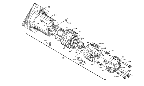
Details of the transmission housing 10 are
best explained while referring to FIGS. 5 and 6 of
the drawings. Tn FIG. 5, the housing 10 is shown
including a mounting flange 82 which is mated to
the bottom of the valve body by means of the
previously mentioned cap screws (76 in FIG 4).
Extending downwardly from mounting flange 82 is a
hollow lead nut housing 84. As is also shown in
FIG. 6, a spline nut 86 having an internal spline
threaded body is attached to the head of a lead
screw 88 by means of socket head cap screws 89.
Lead screw 88 has an axially projecting lead screw
shaft 90, a portion of which is threaded, so as to
retain a lead nut 92 thereon. When in the
assembled relationship, the spline nut 86 is
located completely with the hollow interior of lead
nut housing 84, and the lead nut 92 is located
partially within and secured to lead nut housing 84
by a spaced array of socket head set screws 94.
r ~~l..~l"~ ~~°;
17
Moreover, the spline end 30 of the spline shaft
(26 of FIG. 3) is received within the internally
threaded spline body of spline nut 86 so that a
rotational force imparted to said spline shaft can
be transferred to said spline nut and to the lead
screw 88 connected thereto. In this manner, and as
will be explained in greater detail hereinafter, a
rotation of spline nut 86 causes a corresponding
rotation and linear advancement of the tap 80 via
lead screw shaft 90.
The lead nut 92 is affixed to an oil pump body
96, and each of the lead nut and oil pump body are
threaded onto the lead screw shaft 90 such that the
lead nut 92 and oil pump body 96 are stationary
relative to spline nut 86 and lead nut 92. The oil
pump body 96 has a central opening and a series of
axially extending passages formed therethrough.
One of the passages 98 in oil pump body 96 is sized
to receive therein an oil pump piston 100 so that
an oil pump can be created to periodically squirt
oil, under pressure, from the oil reservoir (12 of
FIG. 1) to the oil spout 78 for lubricating and
cooling the tap 80. Another passage 104 is sized
to receive a check valve (designated 144 in FIG. 8)
to control the flow of oil to oil pump 100. Other
passages in oil pump body 96 are sized to
accommodate a first set of screws 124 for
connecting the pump body 96 to an adjacent spacer
106 and a second set o~ screws for connecting pump
body 96 to lead nut housing 84. An opening in oil
pump body 96 is also included to accommodate a
check valve (designated 144 in FIG. 8). Located
within the central opening of the oil pump body 96
to surround the lead screw shaft 90 is a
linear/rotary bearing (designated 107 in FIG. 7).
Interfaced with this linear/rotary bearing is a
sleeve 108 and a quick disconnect collet 110 which
releasably retains the tap 80.
The spacer 106 which is connected to oil pump
body 96 by bolts 124 also has a central opening arid
a series of axially extending passages formed
therethrough. Coextensively formed with the
central opening of spacer 106 is a relatively large
keyway 112 to receive the collet 110 during
assembly so that the spacer 106 and oil pump body
106 can be connected to one another while
permitting the tap 80 to project outwardly
therefrom. Another passage 114 formed through
spacer 106 is aligned with the passage 98 of oil
pump body 96 and sized to receive the oil pump
19
piston 100. The oil spout 78 communicates with a
piston relief passage 116 so that oil pumped by
piston 190 can be provided via spout 78 to the tap
80. Some of the passages formed through spacer 106
are to receive the aforementioned set of screws 124
while the remaining passages are to receive first
ends of respective actuator return springs 118.
The opposite ends of the actuator return
springs 118 are received at an oil pump actuator
120. The springs 118 initially bias the oil pump
actuator 120 and spacer 106 in spaced alignment
with one another. A plurality of socket head
shoulder screws 124 are received through holes 122
in oil pump actuator 120 so that said actuator is
slidable reciprocally thereon. The screws 124
also extend through passages in the spacer 106 and
oil pump body 96 to interconnect said spacer and
pump body. Oil pump actuator 120 has a centrally
disposed opening within which the tap 80 is
located and isolated (i.e. protected) from the
workpiece. The tap 80 is movable a short distance
in a linear direction (when the punch press
generates an axially directed driving force and
the spline end 30 of the spline shaft moves into
r y,
as
spline nut 96) so as to project outwardly through
the central opening of actuator 120 to tap a hole
of the workpiece.
It is preferable to provide oil pump actuator
120 with a chamfered end surface 126 which will
deflect extrusions in the sheet metal part and
thereby prevent a possible shearing of said
extrusions. It is also preferable to provide the
oil pump actuator 120 with a keyway 128 (best shown
in FIG. 5a) which engages the head 102 of the oil
pump piston 100 to fix the piston relative to the
pump actuator 120. In this manner, every time that
the transmission housing 10 is pushed downwardly
and into contact with a workpiece to tap a hole
therein (in response to an axial force generated by
the punch press) the oil pump actuator 120 is moved
upwardly towards spacer 106 against the bias of
actuator return springs 118. The upward movement
of actuator 120 causes a corresponding movement of
oil pump piston 100, the head 102 of which is
interconnected with the actuator at keyway 128.
Accordingly, oil is delivered, under pressure, to
the tap 80 by way of the piston relief passage.116
and the oil spout 78 of spacer 106. After a hole
has been tapped and the transmission housing 10 is
21
moved out of contact with the workpiece, the
normal bias of springs 118 automatically advances
the oil pump actuator 129 downwardly to its initial
position in spaced alignment with spacer 106.
It may be appreciated that the combination of
elements illustrated in FIG. 5 and located within
transmission housing 10 forms a gearless
transmission which is of reduced size, complexity
and cost relative to the geared transmissions of
conventional tapping units. More particularly, and
as previously disclosed, the axial force applied by
the punch press to the thrust bearing assembly (6
in FIG. 2) induces a rotation of the spline shaft
26 by means of the roller nut (74 in FIG. 4). The
rotary motion of spline shaft 26 is transferred
from the spline end 30 thereof to the lead screw 88
via the spline nut 86, whereby to cause a
corresponding rotation of the lead screw shaft 90.
However, the head of the lead screw 88, which
rotates with the screw shaft 90, moves linearly
towards the stationary lead nut 92 at a slower rate
than the spline end 30 moves linearly through
spline nut 86. Hence, the linear motion of the
thrust bearing assembly 6 is converted into a
rotary motion of the spline shaft 26 (at the roller
22
nut 7~! of FIG. 4), and a relatively large linear
motion of the spline shaft is translated into a
smaller more accurately controlled linear motion of
lead screw 88 and, accordingly, the tap 80 via
lead screw shaft 90. By way of specific example,
because of the receipt and linear movement of the
spline end 30 of spline shaft 26 at the internal
spline of spline nut 86, an approximately 32 mm
linear movement of the thrust bearing assembly (6
of FIG. 4) towards the valve body (8 of FIG. 4) in
response to an axial force generated by the punch
press is translated into an approximately 6.5 mm
linear movement of the tap 80 outwardly from the
oil pump actuator 120 and into the hole of a
workpiece,
The foregoing translation of linear motion
between the thrust bearing assembly 6, the spline
shaft 26 and the tap 80 is accomplished by
establishing equal thread pitches on the lead
screw shaft 90 and the tap 8H. However, the thread
pitch of the screw threaded end of the spline shaft
(which may be varied, as desired) is larger than
the thread pitches of tap 80 and shaft 90.
Therefore, should it be desired to change the pitch
23
of tap 80, a corresponding change in pitch must be
introduced to the lead screw 88 and lead nut 92.
Referring to FIG. 6, details of the quick
disconnect collet 110 are provided for releasably
retaining the tap 80 at the end of transmission
housing 10. Collet 110 includes a collet sleeve
130 which is surrounded by a collet flange 132.
The tap 80 is retained at a notch thereof within a
set of balls located in collet sleeve 130. A
plurality of pins 133 extend through apertures in
the collet flange 132 to receive a respective
plurality of coil springs 134. An additional coil
spring 137 is received through the interior of
collet sleeve 130 to bias tap 80 in a direction
outwardly of the sleeve 130 to make for an easy
removal in case the tap is broken during use. The
remaining coil springs 134 provide the spring
action necessary to remove the tap 80 from collet
sleeve 130 under normal operating conditions. A
compression spring 135 is located at the interior
of the lead screw shaft 90, and one end of the
collet sleeve 130 is positioned within the screw
shaft 90 ahead of spring 135. Spring 135 permits
the collet sleeve 130 to move rearwardly through
lead screw shaft 90 to avoid breaking the tap 80 in
24
the event that the tap fails to find a hole in the
Workplece dfter d linear movement towards SUCK
workpiece. A roll pin 136 is moved through an
axial slot 138 formed in lead screw shaft 90 and
through openings formed in the collet sleeve 130 to
hold the sleeve and spring 135 within shaft 90.
Lastly, a conical collet tip 139 surrounds the
collet sleeve to protect the tap 80 projecting
outwardly therefrom. The collet tip is movable
rearwardly and against the normal bias of springs
134 to move the tap 80 away from its retaining
balls and thereby permit a quick and easy removal
of said tap from the sleeve 130. Should it be
necessary to change the size of the tap, such
change is accommodated by also changing the lead
screw 88, lead nut 92 and the collet 110.
FIG. 7 of the drawings is a cross section of
the tapping head assembly 2 of the tapping
attachment 1 and the interconnection of the
gearless transmission which extends through valve
body 8 and transmission housing 10 for rotating and
advancing the tap 80. The tapping head attachment
1 of FIG. 7 is in the at rest configuration with
the thrust bearing assembly 6 thereof spaced (e. g.
approximately 32mm) above the valve body 8 by means
~~~~~.M~~/~~
of pistons 32. The tap 80 is retracted in and
protected by oil pump actuator 120. zn the at rest
configuration, the thrust bearing assembly 6 is
aligned with the punch press to receive an axially
directed force therefrom whereby to drive bearing
assembly 6 towards valve body 8 and pistons 32
through their respective cylinders 70 (as shown in
FIG. 8).
As previously described, the relatively
complex and large size gearing arrangements common
to the transmissions of conventional tapping units
is advantageously replaced, in the present
invention, by the linear and streamlined alignment
of transmission components includinc7 the spline
shaft 26 connected between thrust bearing assembly
6 and spline nut B6 via the roller nut 74, whereby
the axially directed force generated by the punch
press is converted into a first rotary force by the
roller nut 74. Moreover, the lead screw shaft 90
is interconnected between the lead screw 88 and the
collet 110 by way of lead nut 92 and the
linear/rotary bearing 107 of oil pump body 96, so
that a first rotary force developed by spline shaft
26 and the axial displacement of shaft 26 relative
to the hollow interior of spline nut 86 can be
26
translated into a second rotary force and an axial
displacement of the tap 80. That is to say, and as
was previously described in detail, the pitch of
the thread on the lead nut 92 and lead screw shaft
9H is equal to the pitch of the tap 80. However,
the pitch of the threaded end of spline shaft 26 is
greater than that of tap 80. Different pitches as
just described are possible because of the ability
of spline shaft 26 to both rotate in and move
linearly through the splined interior of spline nut
86. Thus, should the pitch of the lead nut 92 or
lead screw shaft 90 be changed, then a
corresponding change may be achieved in the tap 80.
FIG. 8 of the drawings shows the tapping
assembly 1 of FIG. 7 in the loaded condition after
an axial driving force has been generated by the
punch press and applied to the thrust bearing
assembly 6 (in the direction of the reference
arrow). In this case the bearing assembly 6 is
driven downwardly and into contact with valve body
8 such that pistons 32 are moved through their
respective cylinders 70 to compress the gas
therewithin. Moreover, the spline shaft 26 is both
rotated in and moved axially through the hollow
splined interior of spline nut 86, whereby to cause
a corresponding rotation and axial displacement
(via lead screw shaft 90 of transmission
housing 10) of the tap 89 fox receipt by and
threading of a hole in a sheet metal workpiece.
That is, a rotation of spline shaft 26 causes a
rotation of spline nut 86 relative to the
stationary lead nut 92 and, therefore, an axial
displacement of tap 80 via lead screw shaft 90.
As was previously disclosed when referring to
FIG. 5, each time that the thrust bearing assembly
is advanced, the oil pump actuator 120 is also
advanced into contact with the workpiece, whereby
oil is squirted from the oil spout 78 to the tap
80. Mare particularly, and was also previously
disclosed, the axial displacement of oil pump
actuator 126 towards the workpiece causes a
corresponding displacement of the oil pump piston
1(~PJ which is connected thereto (best shown in FIG.
and 5a). Accordingly, cutting oil is pumped from
the hollow oil reservoir 12 of reservoir assembly
to oil spout 78 by way of an oil supply path 140
(represented by solid referenced arrows) including
a first check valve 142, a second check valve 144,
and relief passage 116 through spacer 106.
z s ~~~.~-'~~ ~~.
What is more, a supply of nitrogen gas is
provided from the hollow nitrogen reservoir 14 of
reservoir assembly 4 to the cylinders 70 of valve
body 8 via a gas supply path 150 (represented by
broken reference arrows). In this manner, the
cylinders 70 will contain a fresh supply of gas to
be compressed therewithin during the downstroke of
pistons 32 so that said pistons can be driven
upwardly through their cylinders 70 as the
compressed gas expands. Accordingly, the thrust
bearing assembly 6 and tap 80 are moved upwardly
relatively to valve body 8 and oil pump actuator
120, respectively, the spline shaft 26 is retracted
relative to spline nut 86 and the tapping
attachment 1 is reset to the at rest configuration
of FIG. 7 to await another axially directed force
generated by the punch press for tapping a
different hole in the workpiece. Thus, it will be
appreciated that the pistons 32 are reciprocated
through their cylinders 70 by means of the punch
press, in a first direction, and by the expansion
of the compressed nitrogen gas, in the opposite
direction, so that the gearless transmission of
the tapping attachment 1 of this invention can be
characterized by a spring-like efficiency for
29
reliably tapping holes at very high speeds and,
therefore, at a reduced cost per hole.
It will be apparent that while a preferred
embodiment of the invention has been shown and
described, various modifications and changes may be
made without departing from the true spirit and
scope of the invention. Fox example, although the
tapping attachment of this invention has been
described as having particular application to a
turret-type punch press, it is to be understood
that the tapping attachment may also be interfaced
with a conventional punch press or a hydraulic or
hydro-mechanical punch press, as well. Having thus
set forth a preferred embodiment of the invention,
what is claimed is: