Note: Descriptions are shown in the official language in which they were submitted.
IM-0214
~ITI.E
SOLID IMAGING METHOD USING PHO~OHARDENABLE
MATERIALS OF SELF LIMITING THICKNESS
1. Field of the Invention
This invention relates to production of three-
dimensional objects by photohardening, and more
particularly to a method utilizing photohardenable
materials characterized by self limiting the depth of
1 0 photohardening during irradiation.
2. Background of the Invention
Many systems for production of three-dimensional
modeling by photohardening have been proposed.
European Patent Application No. 250,121 filed by
Scitex Corp. Ltd. on June 6, 1987, provides a good
summary of documents pertinent to this art area,
including various approaches attributed to Hull,
Kodama, and Herbert. Additional background is
described in U.S Patent No. 4,752,998 issued to Fudim
2~ on June ~1, 1988.
These approaches relate to the formation of solid
sectors of three-dimensional objects in steps by
sequential irradiation of areas or volumes sought to
be solidified. Various masking techniques are
~5 described as well as the use of direct laser writing,
i.e., exposing a photohardenable polymer with a laser
beam according to a desired pattern and building a
three-dimensional model layer by layer.
However, all these approaches fail to identify
practical ways of utilizing the advantages of vector
scanning combined with means to maintain constant
exposure and attain substantially constant final
thickness of all hardened portions on each layer
throughout the body of the rigid three dimensional
object. Furthermore, they fail ~o recogn:ize very
2 ~1~
important interrelations within specific ranges of
operation, which govern the process and the apparatus
parameters in order to render them practical and
useful. Such ranges are those of constant exposure
S levels dependent on the photohardening response of the
material, those of minimum distance traveled by the
beam at maximum acceleration dependent on the
resolution and depth of photohardening, as well as
those of maximum bea~ intensity depend on the0 photospeed of the photohardenable composition.
The Scitex patent, for example, suggests the use
of photomasks or raster scanning for achieving uniform
exposure, but does not suggest a solution for keeping
the exposure constant in the case of vector scanning.5 The use of photomasks renders such techniques
excessively time consvming and expensive. Raster
scanning is also undesirable compared to vector
scanning for a number of reasons, including:
neCessity to scan the whole ~ield even if the
object to be produced is only a very small part
of the total volume,
considerably increased amount of data to be
stored in most cases,
overall more difficult manipulation of the stored
data, and
the necessity to convert CAD-based vector data to
raster data.
On the other hand, in the case of vector scanning
only the areas correspondin~ to the shape of the rigid
3 0 object have to be scanned, the amount of data to be
stored is smaller the data can be manipulated more
easily, and "more than 90% of the CAD based machines
generate and utilize vector data" (Lasers & Optron~cs,
January 1989, Vol. 8, No. 1, pg. 56). The maln reason
why laser vector scanning has not been utilized
3 201~
extensively so far is the fact that, despite its
advantages, it introduces problems related to the
inertia of the optical members, such as mirrors, of
the available deflection systems for the currently
5 most convenient actinic radiation sources, such as
lasers. Since these systems are electromechanical in
nature, there is a finite acceleration involved in
reaching any beam velocity. This unavoidable non-
uniformity in velocity results in unacceptable
1 0 thickness variations. Especially in the case of
portions of layers having no immediate previous levels
of exposure at the high intensity it becomes necessary
to use high beam velocities, and therefore, longer
acceleration times, which in turn result in thickness
non-uniformity. The use of low inter.sity lasers does
not provide a good solution since it makes production
of a solid object excessively time consuming. In
addition, the usefulness of vector scanning is further
min~mized unless at least the aforementioned depth and
exposure level relationships are observed as evidenced
under the Detailed Description of this invention.
No special attention has been paid so far to the
composition itself by related art in the field of
solid imaging, except in very general terms.
Thus, the compositions usu~lly employed, present
a number of different problems, a major one of which
is excessive photohardening depthwise usually
accompanied by inadequate photohardening widthwise.
This problem becomes especially severe in cantilevered
3 0 or other areas of the rigid object, which areas are
not immediately over a substrate.
Therefore, it is an object of this invention to
resolve the problem cited above by utilizing
compositions, the opacity of which increases with
exposure to actinic radiation. This is achieved by
.. . .
4 2014804
introducing into the photohardenable composition
particulate radiation deflecting matter, such that the
difference between the index of refraction of the
composition and that of the deflecting matter
S increases upon irradiation.
United States Patent 3,701,748 (Xroekel)
describes a composition curable under heat and
pressure for molding, containing a thermoplastic
polymer which is soluble in the composition, but
] 0 yields an optically heterogeneous cured composition.
British Patent 1,276,198 describes similar
compositions as United States Patent 3,701,798.
United States Patents 4,078,229, 4,288,861f and
4,446,080 (Swainson et al.) describe holographic
techniques utilizing two or more beams for multiple
proton absorption for production of physical or
refractive index inhomogeneities at the intersection
of the beams.
European Patent Application 250,121 (Scitex
Corp., Ltd.) discloses a three dimensional modelling
apparatus using a solidifiable liquid which includes
radiation transparent particles in order to reduce
shrinkage.
Summary of the Invention
The instant invention is direGted to methods for
direct production of three-dimensional photohardened
solid objects, layer by layer using actinic radiation,
preferably in a beam form such as provided by lasers
for direct writin~, by utilizing compositions, the
opacity of which increases with exposure to actinic
radiation and limits the depth of photohardening.
This is achieved by introducing into the
photohardenable composition particulate radiation
deflecting matter, such that the difference between
,, ~, .. . .
',
2(~14~04
the index of refraction of the composition and that of
the deflecting matter increases upon irradiation.
This invention may be summarized as follows:
A method for accurately fabricating an integral
three dimensional object from successive layers of a
photohardenable liquid composition comprising the
steps of:
(a) forming a layer of a photohardenable
liquid;
~b) p~otohardening at least a portion of the
layer of photohardenable liquid by exposure
to actinic radiation;
(c) introducing a new layer of photohardenable
liquid onto the layer previously exposed to
~5 actinic radiation;
(d) photohardening at least a portion of the
new liquid layer by exposure to actinic
radiation, with the requirement that the
photohardenable composition comprises an
ethylenically unsaturated mGnomer, a
photoinitiator, and radiation deflecting
matter, wherein the deflecting matter has a
first index of refraction, and the rest of
the composition has a second index of
refraction, and wherein the difference
between the first index of refraction and
: the second index of refraction increases by
more than 0.01 upon subjecting the
composition to the radiation of the beam in
order to selectively photoharden it.
Brief Description of the Drawina
The reader's understanding of practical
implementation of preferred embodiménts of the
invention will be enhanced by reference to the
6 20~4~04
following detailed description taken in conjunction
with perusal of the drawing figure, wherein:
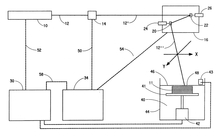
Figure 1 is a block diagram of an apparatus used
to perform the preferred embodiment of the process of
S the instant invention.
Petailed Description of the Invention
The instant invention is directed to compositions
and methods for direct production of three-dimensional
phot~hardened solid objects, layer by layer using
actinic radiation, preferably in a beam form such as
provided by lasers for direct writing, by utilizing
compositions, the opacity of which increases with
exposure to actinic radiation and limits the depth of
photohardening. This is achieved by introducing into
the photohardenable composition particulate radiation
deflecting matter, such that the difference between
the index of refraction of the composition and that of
the deflecting matter increases upon irradiation.
As aforementioned, many systems for production of
three-dimensional modeling by photohardening have been
proposed European Patent Applicatlon No. 250,121
filed by Scitex Corp. Ltd. on June 6, 1987, provides a
good summary of documents pertinent to this art area,
including various approaches attributed to Hull,
Kodama, and Herbert. Additional background is
described in U.S. Patent No. 4,752,498 issued to Fudim
on June 21, 1988.
In a preferred embodiment, an apparatus for
3 0 practicing the present invention is depicted in Figure
1, in the form of a block diagram. The apparatus and
its operation are described below.
Actinic radiation means 10 shown in Figure 1,
which is preferably a high power laser, is used to
provide an actinic radiation beam 12 having a certain
:,
7 ~
intensity. The radiation beam 12 is passed through a
modulator 14, where its intensity may be modulated.
The modulated beam 12' is passed in turn through
deflection means 16 such as a vector scanner in the
S form of a two-mirror 20 and 22 assembly, each mirror
separately driven by a different motor 24 and 26
respectively. By causing mirror 20 driven by motor 24
to turn, the beam is deflected in an X direction,
while by causing mirror 22 to turn, the beam is
1 0 deflected in a Y direction, X direction being
perpendicular to the Y direction. The actinic
radiation beam 12" is thus controllably deflected
towards preselected portions of the photohardenable
composition which is contained in vessel 44 and
IS presents a surface q6. It photohardens a thin layer
48 closest to the surface 46 of a photohardenable
composition 40, to a depth o~ photohardening which
equals the maximum thickness of the layer 48. The
composite movement of the beam is preferably a vector
type movement, and the beam is said to move or be
scanned in a vector mode. Due to the inertia of the
electromechanical deflection means 16, the velocity of
the be~m 12" on the thin layer 48 is also limited by
the inertia and the electromechanical nature of the
deflection means 16.
The deflection of the two mirrors 20 and 22
through motors 24 and 26 respectively is controlled by
the second computer control means 34, while the
grap~ic data c~rresponding to the shape of the solid
3 0 object under production are stored in the first
computer control means 30.
The second computer control means 34 is coupled
with the modulation means 14, the deflection means 16,
and the first computer control means 30, through
control/feedback lines 50, 54, and 58, respectively.
, ~
~he graphic data stored in computer control means 30
are fed to computer control means 34, and after being
processed cause motors 24 and 26 to turn and move
mirrors 20 and 22 accordingly in order to deflect the
beam towards predetermined positions on the thin layer
48. Electrical feedbac~ regarding the relative
moven~ents of the mirrors 20 aDd 22 is provided by the
deflection means to the second computer control means
34 through line S4.
The manner of introducin~ successive layers of
photohardenable liquid and exposing to actinic
radiation such as a laser will generally be by two
methods. In a first method a pool of liquid is
present in a vessel and it is no~ necessary to
introduce additional photDhardenable liquid. ~n such
case a movable table or floor supports ~.he liq-~id.
Initially the table or floor ~s elevate~ ~ith a
portion of the photohardenab~e liquid present above
the table or floor and a ~ortion of the liquid present
in t~e ~essel around ~he edge of the table or floor
and/or underneath it. (Illustratively a table is
present which allows liquid to flow underneath the
table as it is used.) After exposure and
photohardening of a portion of t~e liquid layer above
the table, the table is lowered to allow another layer
of photohardenable liquid to flow on top of the
previous layer followed by exposure of predetermined
area on the newly applied liquid layer. If necessary
due to the shape of the final three dimensional
article the thickness of more than one liquid layer
can be photohardened. This procedure of table or
floor lowering and exposure continues until formation
of the desired three dimensional article occurs.
In a second method a movable table or floor need
not be employed but rather a new quantity of
9 201~8~4
photohardenable liquid is introduced into a vessel
after an exposure step in formation of a new liquid
layer on a previously exposed layer containing both
photohardened material and photohardenable liquid.
Criticality is not present in the manner of liquid
introduction but rather in an ability to photoharden
successive liquid layers.
In Fig~re 1, a movable table 41 is initially
positioned within the photohardenable composition 90,
] O a short predetermined distance from the surface 46,
providing a thin layer 48 between the surface 46 and
the table 41. The positioning of the table is
pro~ided by the placement means 42, which in turn is
controlled by the first computer control means 30
according to the data stored therein. The graphic
data correspondi~g to t~e first layer of the shape of
the rigid object are fed from computer control means
30 to computer control means 34, where they are
processed along with feedback data obtained from
deflecting means 16, and are fed to modulato~ 14 for
controlling the same, so that when the beam travels in
a vector mode on predetermined portions of the thin
layer 98, the exposure remains constant.
When the first layer of the rigid object is
complete, the movable table 41 is lowered by a small
predetermined distance by the placement means 42
through a command from first computer control means
30. Following a similar command from computer means
30, layer forming means, such as doctor knife 43
3 0 sweeps the surface 46 for leveling purposes. The same
procedure is then followed for producing the second,
third, and the following layers until the rigid object
is completed.
In the discussions above and below, the act~nic
radiation, preferably in the form of a beam, is many
,
I 20~4~0~
times referred to as light, or it is given other
connotations. ~his is done to make the discussion
clearer in view of the particular example being
described. ~hus, it should not be taken as
S restricting the scope and limits of this invention.
Nevertheless, the preferred actinic radiation is
light, including ultraviolet (UV), visible, and
infrared IIR) light. ~rom these three wavelength
regions of light, ultraviolet is even more preferred.
] O The formulation of the photohardenable
compositions for solid imaging purposes is very
important in order to receive the desirable effects
and characteristics, regardless of whether the
scanning is of the vector type, raster type, or any
lS other type, and the discussion hereinafter is referred
to in any type of scanning, unless otherwise stated.
However, from the different types of scanning, the
vector type is the preferred type of scanning.
A photohardenable composition for solid imaging
2 0 should contain at least one photohardenable monomer or
oligomer and at least one photoinitiator. For the
purposes of this invention, the words monomer and
oligomer have substantially the same meaning and they
may be used interchangeably.
2~ Examples of suitable monomers which can be used
alone or in combination with other monomers include t-
butyl acrylate and methacrylate, 1,5-pentanediol
diacrylate and dimethacrylate, N,N-diethylaminoethyl
acrylate and methacrylate, ethylene glycol diacrylate
3 0 and dimethacrylate, 1,4-butanediol diacrylate and
dimethacrylate, diethylene glycol diacrylate and
dimethacrylate, hexamethylene glycol diacrylate and
dimethacrylate, 1,3-propanediol diacrylate and
dimethacrylate, decamethylene glycol diacrylate and
dimethacrylate, 1,4-cyclohexanediol diacrylate and
1 0
1 1 20~
dimethacrylate, 2,2-dimethylolpropane diacrylate and
dimethacrylate, glycerol diacrylate and
dimethacrylate, tripropylene glycol diacrylate and
dimethacrylate, glycerol triacrylate and
trimethacrylate, trimethylolpropane triacrylate and
trimethacrylate, pentaerythritol triacrylate and
trimethacrylate, polyoxyethylated trimethylolpropane
triacrylate and trimethacrylate and similar compounds
as disclosed in U.S. Pat. No. 3~380,831, 2,2-di(p-
hydroxyphenyl)-propane diacrylate, pentaerythritol
tetraacrylate and tetramethacrylate, 2,2-di-(p-
hydroxyphenyl)-propane dimethacrylate, triethylene
glycol diacrylate, polyoxyethyl-2,2-di(p-
hydroxyphenyl)propane dimethacrylate, di-(3-
methacryloxy-2-hydroxypropyl) ether of bisphenol-A,
di-(2-methacryloxyethyl) ether of bisphenol-A, di-(3-
acryloxy-2-hydroxypropyl) ether of bisphenol-A, di-(2-
acryloxyethyl) ether of bisphenol-A, di-(3-
methacryloxy-2-hydroxypropyl) ether of 1,4-butanediol,
2~ triethylene glycol dimethacrylate,
polyoxypropyltrimethylol propane triacrylate, butylene
glycol diacrylate and dimethacrylate, 1,2,4-
butanetriol triacrylate and trimethacrylate, 2,2,4-
trimethyl-1,3-pentanediol diacrylate and
dimethacrylate, 1-phenyl ethylene-1,2-dimethacrylate,
diallyl fumarate, styrene, 1,~-benzenediol
dimethacrylate, 1,9-diisopropenyl benzene, and 1,3,5-
triisopropenyl benzene. Also useful are ethylenically
unsaturated compounds having a molecular weight of at
3 0 least 300, e.g., alkylene or a polyalkylene glycol
diacrylate prepared from an alkylene glycol of 2 to 15
carbons or a polyalkylene ether glycol of 1 to 10
ether linkages, and those disclosed in V.S. Pat. No.
2,~27,022, e.g., those having a plurality of addition
polymerizable ethylenic linkages particularly when
.
.
1 2 201~804
present as terminal linkages. Particularly preferred
monomers are ethoxylated trimethylolpropane
triacrylate, ethylated pentaerythritol triacrylate,
dipentaerythritol monohydroxypentaacrylate, 1,10-
decanediol dimethylacrylate, di-~3-acryloxy-2-
hydroxylpropyl)ether of bisphenol A oligomers, di-(3-
methacryloxy-2-hydroxyl alkyl)ether of bisphen~l A
oligomers, urethane diacrylates and methacrylates and
oligomers thereo~, coprolactone acrylates and
methacrylates, propoxylated neopentyl glycol
diacrylate and methacrylate, and mixtures thereof.
Examples of photoinitiators which are useful in
the present invention alone or in combination are
described in U.S. Pat. No. 2,760,863 and include
vicinal ~etaldonyl alcohols such as benzoin, pivaloin,
acyloin ethers, e.g., benzoin methyl and ethyl ethers,
benzil dimethyl ketal; ~-hydrocarbon-substituted
aromatic acyloins, including -methylbenzoin ~-
allylbenzoin, ~-phenylbenzoin, l-hydroxylcyclohexyl
phenol ketone, diethoxyphenol acetophenone, 2-methyl-
1-[4-(m~t~lylthio)phenyl~-2-morpholino-propanone-1.
Photoreducible dyes and reducing agents disclosed in
U S Pat Nos. 2,B50,445, 2,875,047, 3,097,096,
3,074,974, 3,097,097 and 3,145,104, as well as dyes of
the phenazine, oxazine, and quinone classes, Michler's
ketone, benzophenone, acryloxy benzophenone, 2,4,5-
triphenylimidazolyl dimers with hydrogen donors
including leuco dyes and mixtures thereof as described
in U.S. Pat. Nos. 3,427,161, 3,479,185 and 3,549,367
can be used as initiators. Also useful with
photoinitiators are sensitizers disclosed in U.S. Pat
No. 4,162,162. The photoinitiator or photoinitiator
system is present in 0.05 to 10% by weight based on
the total weight of the photohardenable composition.
Other suitable photoinitiation systems which are
,
12
13
thermally inactive but which generate free radicals
upon exposure to actinic light at or below 185C
include the substituted or unsubstituted polynuclear
quinones which are compounds having two intracyclic
carbon atoms in a conjugated carbocyclic ring system,
e.g., 9,10-anthraquinone, 2-methylanthraquinone, 2-
ethylanthraquinone, 2-tert-butylanthraquinone,
octamethylanthraquinone, 1,4-naphthoquinone, 9,10-
phenanthraquinone, benz(a)anthracene-7,12-dione, 2,3-
] 0 naphthacene-5,12-dione, 2-methyl-1,4-naphthoquinone,
1,4-dimethyl-anthraquinone, 2,3-dimethylanthraquinone,
2-phenylanthraq~inone, 2,3-diphenylanthraquinone,
retenequinone, 7,8,9,10-tetrahydronaphthacene-5,12-
dione, and l,2,3,4-tetrahydrobenz(a)anthracene-7,12-
dione. Also, alpha amino aromatic ketones,
halogenated compounds like trichloromethyl substituted
cyclohexadienones and triazines or chlorinated
acetophenone derivatives, thioxanthones in presence of
tertiary amines, and titanocenes
Although the preferred mechanism of
photohardening is free radical polymerization, other
mechanisms of photohardening apply also within the
realm of this invention. Such other mechanisms
include but are not limited to cationic
polymerization, anionic polymerization, condensationpolymerization, addition polymerization, and the like.
Other components may also be present in the
photohardenable compositions, e.g., pigments, dyes,
extenders, thermal inhibitors, interlayer and
generally interfacial adhesion promoters, such as
organosilane coupling agents, dispersants,
surfactants, plasticizers, coating aids such as
polyethylene oxides, etc. so long as the
photohardenable compositions retain their essential
properties.
14 20~
In this discussion a clear distinction sh~uld be
made between a photohardenable and a photohardened
composition. The former refers to one which has not
yet been subjected to irradiation, while the latter
refers to one which has been photohardened by
irradiation.
When the composition is clear to the radiation
beam, the depth of photohardening is considerably
larger than the width of photohardening, mainly
because the beams utilized, such as laser beams, and
the like, are well collimated and focused. Addition
of inert particulate matter, which is transparent to
the radiation in the environment of the composition,
has certain well recognized advantages, such as
reduction of shrinkage upon polymerization or
photohardening in general, and often increase in
photospeed due to the reduction of the amount of
active composition, which is subject to shrinkage, per
unit of volume.
~0 The large depth of photohardening is not a very
big problem in areas supported by a substrate, since
the depth is determined primarily by the thickness of
the liquid layer on top of the substrate. However, in
cantilevered unsupported areas, where the thickness of
the liquid is very large, it becomes a serious
disadvantage, as the depth of photohardening is not
controlled or limited any more by the substrate. This
is actually the area where the differences between
conventional two dimensional imaging and solid or
three dimensional imaging manifest themselves as being
most profound. This is particularly important when
there are uncontrollable exposure variations, which
may result in thickness variations, and poor
resolution. Thus a way to control the thickness is
needed.
14
1 ~ 201~304
In addition to the lack of control of the depth
of photohardening, there is one more problem having to
do with resolution considerations. Except in very
limited occasions, it is highly desirable for the
5 resolution or tolerances of a part to be comparable in
all dimensions. It does not make much sense to have
high resolution in one dimension and very poor
resolution in another dimension since the final
resolution is going to be necessarily considered as
I O poor, except in rare occasions as mentioned above In
clear compositions, the depth to width ratio is high,
and thus the resolution widthwise is accordingly
higher than the resolution depthwise. As a matter of
fact, the resolution is inversely proportional to the
IS dimensional units, and therefore, if the depth to
width ratio is for example 5, the width resolution
will be five times better than the depth resolution,
when other factors do not play an active role. Thus,
high transparency of the composition becomes in
general undesirable. Preferable regions of depth to
width ratios are 7:1 to 1:1, and more preferable 3:1
to 1:1.
The task of reducing the transparency or in other
words increasing the optical density of the
photohardenable composition sounds as a rather
straightforward one, and it is, if photospeed and
other important parameters are not taken into account
For example, addition of a radiation absorbent in the
composition will decrease the depth of photohardening
without affecting considerably the width. Typical
absorbents are dyes. The monomers or oligomers of the
composition may also act as absorbants to different
degrees. However, if a dye, or other absorbent is
used, the part of the radiation which is absorbed by
, ~
20~480
radiation which is absorbed by it will not be
available to directly promote photohardening.
A separate phase of dispersed particulate solid
matter, emulsified liquid matter, or even matter in
the form of gas may be utilized to control the
depth/width relation, under conditions, which involve
refraction or reflection or scattering of light or any
combination thereof, labelled as radiation deflection
for the purposes of this discussion. Suitable
conditions constitute for example a substantial
difference between the refraction index of the
radiation deflection matter and the rest of the
photohardenable composition. If everything else is
kept constant, as the content in separate phase of
radiation deflecting matter is increased, so does the
width in expense of the depth. Since the radiation is
not absorbed by the deflection matter but just
deflected, no considerable loss of radiation occurs,
and therefore, there is no substantial loss of
photospeed.
The instant invention is directed to methods for
direct prodvction of three-dimensional photohardened
solid objects, layer ~y layer using actinic radiation,
preferably in a beam form such as provided by lasers
for direct writing, by utilizing compositions, the
opacity of which increases with exposure to actinic
radiation and limits the depth of photohardening.
This is achieved by introducing into the
photohardenable composition particulate radiation
deflecting matter, such that the difference between
the index of refraction of the composition and that of
the deflecting matter increases upon irradiation.
Since the general rule is that upon
photohardening, the refraction index increases, for a
definite increase in the difference between the
16
1 7 Z~14804
refraction indices of the radiation deflection matter
and the rest of the photohardenable composition it
would be preferable that the refraction index of the
deflection matter, which can be a dispersed solid or
S an emulsified liquid as discussed earlier, is smaller
than that of the rest of the photohardenable
composition before photohardening occurs. Thus, for
this mechanism to be effective, the refraction index
of the radiation deflection matter should preferably
1 0 be smaller than that of the rest of the
photohardenable composition before the photohardening
process takes place. Otherwise, upon irradiation, the
composition would have to first become clear before
becoming opaque again, and the change in refraction
index would have to be considerably larger, both of
which are undesirable. Since the relative increase of
the difference between the two refractive indices upon
photohardening is inversely proportional to the
initial difference of the two indices, it is
preferable that the values of the two indices are
close to each other but still different in the
photohardenable composition. They should be different
even before irradiation of the photohardenable
composition to prevent excessive beam penetration at
the beginning. In any case, the refraction index of
the deflection matter should be smaller than that of
the rest of the photohardenable composition by 0.01-
0.03, and preferably smaller than by 0.01-0.02. Also,
the increase in refraction index difference before and
3 0 after photohardening should be at least 0.01,
preferably higher than 0.02, and even more preferably
higher than 0.04.
In other words, for the purposes of this
invention, the liquid photohardenable composltlon must
contain an ethylenically unsaturated monomer, a
18
photoinitiator, and radiation deflecting matter,
wherein the deflecting matter has a first index of
refraction, and the rest of the composition has a
second index of refraction, and wherein the difference
between the first index of refraction and the second
index of refraction increases by more than 0.01 upon
subjecting the composit}on to the radiation of the
beam in order to selectively photoharden it. It is
preferable that the first index of refraction is
smaller than the second index of refraction.
Initially, if we call "particle" each individual
unit of the separate phase of the dispersed or
emulsified radiation deflection matter in the
photohardenable composition as aforementioned, the
maximum particle size, measured as the average
particle diameter, should be smaller than the depth of
photohardening, but not width necessarily. It is
preferred that not only substantially all particles
are smaller than the depth of photohardening, but also
that at least 90% of the particles are smaller than
half the depth of photohardening, and even more
preferred that at least 90% of the particles are
smaller than one tenth the depth of photohardening.
In order to be effective for their purpose, the
majority of particles should also be preferably larger
than approximately half the wavelength of the beam's
radiation. At approximately half the wavelength, the
; scattering yield of the particles attains a maximum
value, while it decreases rapidly as the size of the
3 0 particles goes down. On the other hand, as the
particle size increases ovex about half the wavelength
of the radiation, the scattering yield also starts
dropping, but at a lower pace. As the particle size
increases even more, the phenomena of refraction and
reflection start prevailing. In practice there are
18
.
.
19 Z01~ )4
only limited situations where all particles have
substantially the same size, in which case they are
called monodisperse. Generally, there is a
distribution of particle sizes providing a combination
5 of many types of actinic-radiation deflection.
The preferred deflecting matter, which can be of
organic or inorganic nature, includes but is not
limited to:
partic~es consisting of linear or branched
polymers in the form of homogeneous beads or
of core/shell type structure of such chemical
types as cellulose propionate, polyethylene,
polypropylene, po~yisobutylene Poly methyl
methacrylate, copolymers of acrylonitrile and
methyl methacrylate, polyamides,
polyvinylidene fluoride, polyvinyl fluoride,
and the like, as well as mixtures thereof;
particles of crosslinked polymers like poly
trimethylol propane tri acrylate, poly
trimethylol propane tri methacrylate, poly
trimethylol pr~pane ethoxylated triacrylate,
poly hexamethylene glycol diacrylate, poly
hexamethylene glycol dimethacrylate, and the
like, as well as mixtures thereof;
particles consisting of inorganic materials
which have a refractive index in the range of
about 1.39 to 1.55, are insoluble in the
photopolymerizable liquid and do not inhibit
photopolymerization, like magnesium sulfate
3 0 heptahydrate, lithium fluoride, sodium
carbonate, monobasic potassium carbonate, and
the like, as well as mixtures thereof.
The preferred content in radiation deflection
matter, although dependent on many parameters, such as
refraction index, particle size, particle size
l 9
.
Z01480
distribution, particle shape, and the like, should be
in general in the region of 5-40~ by volume of the
total mixture with a mean diameter of particle of 0.5
to 5 micrometers.
A sulfur linked trimethylol propane triacrylate
oligomer (Example 1) containing dispersed core/shell
polymer demonstrates the phenomenon of increasing
opacity ~optical density) during the photohardening
step, and of limiting the depth of photohardening to
almost half that of the depth of photohardening in the
case of a composition containing no dispersed
core/shell polymer (Example 2).
The same sulfur linked trimethylol propane
triacrylate oligomer (Example 3) containing dispersed
crosslinked pure trimethylol propane triacrylate also
demonstrates this phenomenon of increasing opacity
(optical density) during the photohardening step, and
limiting of the depth of photohardening to almost half
that of the depth of photohardening in the case of a
composition containing no dispersed trimethylol
propane triacrylate polymer (Example 4). In contrast,
pure trimethylol propane triacrylate monomer
containing dispersed crosslinked pure trimethylol
propane triacrylate (Example S) does not give the
self-limiting advantage in depth of photohardening
when compared to the same composition containing no
dispersed polymer (Example-6).
Examples of photohardenable compositions are
given below for illustration purposes only, and should
not be construed as restricting the scope or limits of
this invention. Quantities are given by weight in
grams.
EXAMPLE 1
The following ingredients were mixed:
2 1 2~1~3~ `
Plex 6696 91 g
RCP 1674 5
Benzildimethylketal 4
Plex 6696 is an oligomer sold by Roehm GmbH.,
5 Darmstadt, West Germany. It is represented by the
formula
TMP TA [ S - TMP TA ] - S - TMP TA
where ~MPTA stands for trimethylol propane
l 0 triacrylate, and S for sulfur. The refractive index
of the oligomer is n=1.989.
RCP 1674 is a coretshell type polymer made by
Du Pont, having a core of butyl acrylate, butylene
glycol diacrylate, and allyl methacrylate, and a shell
] 5 of methyl methacrylate. ~his polymer has a refraction
index of n=1.477, and a core to shell weight ratio of
4:1. It was prepared as shown in Example 7.
A thick layer of photohardenable composition was
exposed to a range of 0-100 mJ/cm2 with a filtered
2 0 (transmittance 360 nm) high pressure Hg lamp.
The thickness of the solid layer received at an
exposure of 80 mJ/cm2 was 0.7.
The difference in refraction indices was 0.012
before exposure, and 0.095 after exposure, as
2 5 Polymerized Plex 66g6 was found to have a refraction
index n=1.522 in an independent experiment.
EXAMPLE 2
~he following ingredients were mixed together:
Plex 6696 96
Benzildimethyl3cetal 4
A thick layer of photohardenable composition was
exposed to a ran~e of 0-100 mJ/cm2 with a filtered
3 5 (transmittance 360 nm) high pressure Hg lamp.
2l
.... . .
: : - . . .' ' ' '
2~14~304
22
The thickness of the solid layer received at an
exposure of 80 mJ/cm2 was 1.3.
EXAMPLE ~
The following ingredients were mixed:
Plex 6696 99.7
Irgacure 651 0.5
Cross~inked ~MPTA 4.8
}0 Irgacure 651 is 2,2-dimethoxy 2-
phenylacetophenone, and available from CIBA GEIGY.
The crosslinked TMPTA ttrimethylol propane
triacrylate) had a particle size of 1.61 micrometers
population mean, a~d 4.52 micrometers volume mean.
lS A thick layer of this photohardenable composition
was exposed to a range of 0-100 mJ/cm2 with a filtered
(transmittance 360 nm) high pressure Hg lamp.
The maxim~m thickness of the soli~ layer received
was approximately 0.5 mm, and the threshold energy for
incipient photopolymerization was 12 mJ/cm2.
EXAMPLE 4
The following ingredients were mixed:
Plex 6696 99-5
Irgacure 651 0 5
A thick layer of this photohardenable composition
was exposed to a range of 0-100 mJ/cm2 with a filtered
ttransmittance 360 nm) high pressure Hg lamp.
The maximum thickness of the solid layer received
was approximately 1.8 mm, and the threshold energy for
incipient photopolymerization was 20 mJ/cm2.
22
2 3 20~04
EXAMPLES 5 and 6
The following ingredients were mixed:
TMPTA 32 g 32 g
Benzildimethylketal 0.9 0.9
Crosslinked TMP~A 7
(diameter 1.61 micrometers)
The two mixtures were exposed in a Petri dish
through a circular mask from the bottom using the 360
nm part of a filtered high pressure Hg lamp. At an
exposure of 120 mJ/cm2, the thickness of the samples
of Examples 5 and 6 were O.9S and 1.00 mm,
respectively.
EXAMPLE 7
A core-shell polymer was prepared as follows:
Core
2388 gm of deionized water and 37.5 gm of a 30%
aqueous solution of sodium dodecyl sulfonate were
charged to a four-neck five liter flask equipped with
a mechanical stirrer, condenser, heating mantle,
addition funnel, thermometer and nitrogen inlet. The
; contents of the flask were purged with nitrogen, at
room temperature, for 30 minutes and then heated up to
; 80C. At that temperature, 1/8 of a monomer charge
consisting of 1046 gm of butyl acrylate (BA), 279 gm
of allyl methacrylate (AM~) and 70 gm of 1,4 butylene
glycol diacrylate (BGD) was added in one shot. ~his
; 30 was followed immediately by one shot additions of l9
ml of a 7% solution of sodium hydrogen phosphate, and
20 ml of a 5% solution of ammonium persulfate ~both
solutions were aqueous). The heat was turned off and
the reaction mixture was allowed to exotherm. When
the exotherm peaked at ~4C, the remainder of the
23
'. : . '
. . . .
2 4 2014804
monomer charge was added over a 90 minute period with
intermittent heating to maintain the reaction
temperature between 80 and 85C. When the monomer
(total monomer charge 1345 grams) addition was
finished, the reaction mixture was heated at 80-85C
for an additional 2.5 hours. The final product was a
bluish emulsion with 35.1% solids and had a particle
size of 0.097 micron. The ratio of the monomers in
this case was BA/BGD/AMA = 75/5/20.
Shell
2000 gm of the core emulsion, described above,
was placed in a five liter flask equipped similarly to
the one used for the core synthesis. The contents of
the flask were purged with nitrogen, at room
temperature, for 30 minutes. After the nitrogen
purge, the flask was charged, with stirring, with a
mixture consisting of 1.45 gm ammonium persulfate, 2.9
gm of a 30% aqueous solution of sodium dodecyl
sulfonate, and 332 gm of deionized water, over a 30
minute period. The contents of the flask were then
heated up to 85C, and 179 gm of methyl methacrylate
were adde~ over 60 minutes. When all the monomer had
been added, the reaction mixture was heated for an
additional 2 hours. The flnal product was a bluish
emulsion with 36.2~ solids and a particle size of
0.107 micron. The core to shell ratio was
substantially 4:1.
The bluis~ emulsion was placed in a freezer for 3
days and then it was thawed, filtered, washed with
deionized water, and dried at room temperature for
about 3 days. For large samples, such as in the case
of semiworks or plant batches, spray dryinq techniques
involving hot air of 100 to 150C may be used.
24
, .