Note: Descriptions are shown in the official language in which they were submitted.
¦ It has become accepted practice in the orthopedic field
to use devices known as intramedullary nails to stabilize
fractured bones. In particular, intramedullary nails are used
for stabilizing fractures of the tibia and of the femur to
thereby enable the bones to heal properly.
¦ The nails are adapted for insertion into the
l intramedullary canal of the bone which may be reamed or left
¦ unreamed, depending on the situation at hand. Locking screws are
often inserted through the bone to lock the nail in place. This
method has proven valuable because it reduces the incidence and
severity of malunion or displacement of the fracture. It allows
the patient to apply weight to and walk on the injured bone
earlier, thus, reducing the amount of muscle atrophy.
Various intramedullary nails have heretofore been known
and disclosed in the prior art. Prior art nails can be broken
down by category:
First, many intramedullary nails have been proposed
which are formed of a solid rod material. These have been found
to be much too rigid to follow the usually imperfect
intramedullary bone canal, and their insertion has all too often
caused chipping of the bone material.
Nails formed of sheet metal have been proposed to
provide greater flexibility. Some of these nails have been
formed with closed cross-section and others have been formed into
open cross-section configurations. To obtain desired
flexibility~rigidity characteristics and to provide sufficient
rea about the nail to allow proper revascularization, such nails
are generally formed with other than circular cross-section.
¦That is, grooves on Elat walls are often bent into the side walls
¦of the sheet metal. Examples of such nails are found in U.S.
¦patent 4,621,628 to Brudderman, U.S. Patent 4,697,585 to
¦Williams, European publication 0273872, U.S. publication
¦2,114,005, British publication 1,593,440, and Zimmer publication
¦ A More Precise View of Interlocking Nails." Such sheet metal
nails have proven to be relatively inefficient in their
manufacture, and relatively difficult to modify in their
l configuration. More specifically, difficulties, inherent in the
¦ bending operation necessary to provide sheet metal nails with
non-circular cross-section, have placed limitations on the
ability to economically provide nails of cross-section which,
for example, have grooves which are varied in their depth.
l Other nails have been proposed which are formed from a
¦ rod material with a central longitudinal bore disposed
therethrough. Such a bore provides a flexibility which is
improved over that of the solid axis, but remains less than
desirable. Examples of such nails are disclosed in U.S. Patent
4,103,683 to Neufeld, U.S. Patent 4,446,857 to Otte, et al., U.S.
Patent 4,622,959 to Marcus, European publication 0118778 and
European publication 0008758.
Althou~h the prior art nails have found varying degrees
of success, there remains a need in the field for an
intramedullary nail with a more desirable flexibility and with
features which allow for easy and efficient modifications to the
nail configuration during manufacture.
In accordance with the present invention there is
rovided a tubular intramedullary nail having an elongated body
with a pro~lmal head portion, an intermediate portion and a
2?~ ~
¦distal end portion. The nail is formed o a rod material with a
¦centrally located longitudinal bore extending therethrough. A
slot extends from the distal end longitudinally through a portion
l of the proximal head portion. Four lon9itudinal grooves are cut
¦ along a major portion of the intermediate portion and are
equally s~aced about the circumference of the nail; such groove
cutting being known as fluting. One of the grooves is
l coextensive with a portion of the longitudinal slot.
¦ This shape provides a more desirable flexibility
¦ because the grooves, in addition to the slot and the longitudinal
bore, provide flexibility in various planes. Furthermore, the
shape of the grooves allows them to be readily machined into the
stock material with various shapes and depths. Thus, nails of
l various configuration can be easily manufactured without having
to significantly modify the manufacturing operation. Rather,
mere adjustment to, for example, the depth or radius of the
groove cuts can provide the desired modifications. Furthermore,
the lengths of the various grooves and slots cut into the nail
can be readily varied. Variations in the lengths oE grooves and
slots is important in concentrating stresses to areas of the nail
where it will not prove damaging and which are otherwise
unstressed or less stressed.
The design of this nail further provides the
availability of a greater area for revascularization in and
around the nail. Because the nails can be readily provided with
a variety of groove depths and shapes, the most advantageous
configuration in terms of allowing revascularization can be
formed for each nail.
Accordingly, it is an object of the present invention
to provide intramedullary nails with improved flexibility.
1~ 2'`~
l It is also an object of the present invention to
¦ provide intramedullary nails formed such that their manufacturing
operations can be readily adjusted to provide various nail
l configurations.
S A further object of the present invention is to provide
intramedullary nails which allow improved revascularization.
Yet another object of the present invention is to
provide intramedullary nails wherein stresses are directed to
areas of the nail which will not be damaged thereby.
A still further object of the present invention is to
provide intramedullary nails with the above-noted advantages for
use in the treatment of fractured femurs and for use in the
treatment of fractured tibias and humerus.
Additional features, objects and advantages of the
invention will become apparent from the drawings and the
following detalled description.
The invention will be further described with reference
o the accompanying drawings in which:
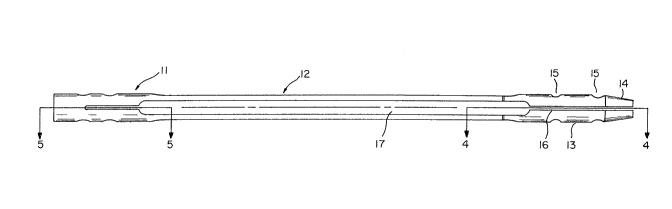
Fig. 1 is an anterior side plan view of an
ntramedullary nail according to the present invention for use in
ending fractured femurs;
Fig. 2 is a side view of the femoral intramedullary
ail shown in Fig. l;
Fig. 3 is a posterior side plan view of the femoral
ntramedullary nail shown in Fig. l;
Fig. 4 is a cross-sectional view of an intramedullary
ail taken along line IV-IV of Fig. l;
Fig. 5 is a sectional view of an intramedullary nail
taken along line V-V of Fig. l;
1 2 r - ; ~
Fig. 6 is a cross-sectional view of an intramedullary
nail taken along line VI-VI of Fig. 2;
Fig. 7 is a cross-sectional view of an intramedullary
l nail taken along line VII-VII of Fig. 2:
¦ Fig, 8 is an end view of the distal end of the
intramedullary nail shown in Fig. l;
Fig. 9 is an anterior side plan view of an
intramedullary nail according to a second embodiment of the
l present invention for use in mending fractures of the tibia or
I humerus;
Fig. 10 is a posterior side plan view of the
intramedullary nail shown in Fig. 9
Fig. 11 is a side view of the tibial or humeral
l intramedullary nail shown in Fig. 9;
¦ Fig. 12 is a cross-sectional view of an intramedullary
nail taken along line XII-XII of Fig. 10
ig, 13 is a cross-sectional view of an intramedullary
nail taken along line XIII-XIII of Fig. 10; and
l Fig. 14 is a cross-sectiona~ view of an intramedullary
¦ nail taken along line XIV-XIV of Fig. 11.
~ igure 1 shows an improved intramedullary nail 10. The
nail is formed of a solid rod material with a centrally located
l longitudinal bore therethrough to form a hollow elongated body
l with a proximal head por~ion 11, an intermediate portion 12 and a
distal end portion 13. The distal end portion includes a tapered
¦point 14.
This femoral nail 10 is insertable into the
ntramedullary canal of the femur and includes holes 15 at its
distal end for reception of locking screws which hold the nail
l 2~
against movement both axially and torsionally. The proximal head
portion also includes holes 21 or reception of locking screws.
The longitudinal bore 22 extends throughout the length
of the nail. This bore not only provides added flexibility to
the nail but also provides for the reception of a guide wire
which aids in the insertion of the nail into the bone canal.
A slot 16, which radiates outwardly from the bore 22 to
the nail surface, extends longitudinally along the anterior side
of the nail from the point 14 up through a portion of the
proximal head portion. This slot allows for greater flexibility
of the nail and allows the distal portion of the nail to be
squeezed together while first being inserted into the canal.
Upon insertion, this portion of the nail expands and helps to
hold the nail against movement within the canal. Note that the
slot 16 extends upwardly to just above the apertures 21 (to be
described later). This is important because the end of this slot
is a point of stress concentration and the proximal end of the
ail has a lesser amount of stress induced therein than other
ortions of the nail. The slot ends below the head of the nail,
owever, so as to provide an adequately strong insertion point
or an insertion tool.
A longitudinal groove 17, which is coextensive with a
ortion of the slot 16, radiates outwardly from the bore 22 to
he outer periphery oE the nail body. the end 23 of groove 17
earest to the lead of the nail is angled inwardly toward the
roximal end of the nail so that the guide wire does not catch on
corner when the nail is inserted over the guide wire.
imilarly, the end 27 of the groove 17 nearest to the point 14 of
he nail is angled inwardly toward point 14 so that the guide
wire does not catch on a corner in the event that a reinsertion
~ 2 !, ~
¦of the guide wire into the bore 22 is required after its initial
¦removal.
¦ Along with groove 17, three other grooves 18, 19 and 20
¦extend along the intermediate portion 12 of the nail and are
¦ spaced about the periphery of the nail. Each end of each of the
grooves is preferably gradually tapered outwardly. Although the
¦grooves 17, 18, 19 and 20 can be formed of various depths and
with various lengths, in the preferred embodiment the groove 17
l on the anterior side of the nail is the longest of the four
¦ grooves, the groove 19 on the posterior side of the nail is the
shortest of the four grooves and the two remaining grooves 18 and
20 are of a length intermediate that of grooves 17 and 19. This
length distribution provides that the stresses incident in the
nail will be directed around to the anterior side of the nail
where they are more readily dissipated, especially due to the
presence of the slot 16 on the anterior side of the nail.
Furthermore, in the preferred embodiment, at least grooves 18 and
20 are of equal depth and shape.
An offset neck 30 is formed near the distal end portion
13 of the nail so as to provide a reduced distal diameter. This
allows for easier insertion of the nail into the intramedullary
canal, and if reaming of the canal is necessary, it prevents the
requirement of over-reaming. Although the neck 30 can be formed
at various angles, in the preEerred embodiment, the neck is
formed by a 30 degree angle radiating inwardly toward the distal
end.
As previously mentioned, holes lS and 21 are provided
at each end of the nail and are adapted for the receipt of
ocking screws. In this femoral nail embodiment, the holes 15
are preferably transverse and the holes 21 are preferably
~ ~1,AI''13
mutually perpendicular and at angles of 45 degrees with respect
to the longitudinal axis of the nail.
l As shown in Figure 4, the end of the head portion is
¦ provided with a screwthreaded bore 24 and a slot 25. These
¦ provide for insertion of tools used for inserting the nail into
the canal, for angularly orienting the nail, and for aligning the
locking screws into the holes 15 and 21.
Referring now to Figures 7 through 12, a second
embodiment is shown in which like elements are designated by like
numerals. So as to eliminate redundancy, features of this tibial
nail embodiment which are the same as features of the femoral
nail embodiment will not be described a second time. Thus, it
will be understood that features of the second embodiment not
specifically described are equivalent to corresponding features
of the first embodiment.
In this embodiment, the hollow tibial intramedullary
nail 100 has an elongated body with a distal end portion 13, an
in~ermediate portion 12 and a proximal head portion 111 which is
angled with respect to the intermediate portion. Tibial nail 100
is adapted for use in the tibia and, as with femoral nail 10, is
adapted for insertion into the intramedullary canal.
The distal end portion 13 is identical to that of the
femoral nail and includes a tapered point 14 and transverse
locking screw holes 15. Also a slot 16 extends from the point 14
up through a portion of the proximal head portion 12.
As with the femoral nail, the tibial nail includes
longitudinal grooves 17, lB, 19 and 20 spaced about the periphery
of the intermediate portion 12, with groove 17 coextending with a
ortion of slot 16 and radiating outwardly from bore 22 to the
outer periphery of the nail body. The grooves can be cut to
~J'V'~
¦various depths to provide various flexibility characteristics and
¦to allow different amounts of area open to revascularization.
he end of the head portion 111 includes a
¦screwthreaded bore 124 and a slot 125 for the receipt of tools
¦used for insertion of the nail into the canal, for properly
¦angularly orienting the nail into the canal, and for aligning the
¦locking screws with the holes 15 and 121.
~he tibial nail, unlike the femoral nail, has its head
¦ portion angled with respect to the intermediate portion, and
¦ includes transverse holes 121 rather than angled holes for
I receiving the locking screws. The tibial nail, like the femoral
¦ nail, includes a longitudinal bore 122 along the length of its
¦ axis. An opening 126 is provided at the outside of the bend in
I the head portion so that the longitudinal bore 122 remains
¦ straight. This is necessary because the guide wires used for
¦ insertion of the nail are generally too rigid to go around the
¦ bend in the head portion.
¦ The intramedullary nails described above are preferably
I made of stainless steel but may be of any material commonly used
¦ for this type of device. Although the nails can be of any useful
dimensions, the femoral nails preferably have a length from 300
¦ millimeters to 500 millimeters and a diameter from 10 millimeters
to 20 millimeters and the tibial and humeral nails preferably
l have a length from 240 millimeters to 380 millimeters and a
I diameter from 9 millimeters to 15 millimeters.
Many variations of the embodiments disclosed may be
made without departing from the spirit and scope of the
invention. It is to be understood, therefore, that this
nvention is not to be limited to the disclosed embodiments
except as defined in the appended claims.