Note: Descriptions are shown in the official language in which they were submitted.
2015038
~ or Use with Wood Flaking Machines
Field of the Invention
The present invention relates to a device suitable for
continuously feeding to flaking machines wood pieces, ~ore
particularly, logs whose average unit length is approx. 2.5m.
The normally uniform length of such logs is by and large set
by the allowable loading width of the vehicles used for their
transport to the mill. The length of timber felled in
permanently cold climatic zones may, on the other hand, be
limited by the dimensions of the thawing basins required to
thaw them out prior to further processing.
Backqround of the Invention
Rationalized production of high-quality, uniform wood
flakes destined for immediate conversion into high-performance
intermediate products such as particle board or particle
profile requires that the logs be fed in piles, properly
aligned and parallel to each other, in uniform, unbroken
sequence, into the flaking chamber of the flaking machine,
where they can be chewed into wood flakes, the fibres being
parallel to the cutting direction. The feasability of this
process depends on matching the length of individual log
sections to the effective cutting width of the flaking machine
in order to obviate the presence, when the flaking chamber has
been loaded to its effective working level, of short unusable
sections. The latter, which are mostly disc-shaped, slide
about uncontrolled, their fibres being no longer parallel to
the cutting knives. Such improper orientation of the
feedstock results in an unacceptably high proportion of fines
in the flake product, causes fluctuations in the power
requirement of the machine and quickly wears down the flaking
knives. Such economic considerations compel the search for a
log feeder on flaking machines whose design and method of
processing prevents the occurrence of errant, unusable log
ends in the flaking chamber.
Prior Art
United States Patent No. 4,784,198 issued to Wilhelm
Pallmann on November 15, 1988 discloses a feed device that in
~015038
great measure satisfies such technical requirements. This
prior art device consists substantially of a flow trough
which, feeding into the flaking chamber of the flaking
machine, runs underneath a loading magazine. The logs, fed by
a transverse conveyor, are marshalled into a pile and properly
oriented for subsequent flaking. When the V-shaped loading
magazine floor comprising two hinged flaps falls open, the
now-compact log pile drops into the flow trough whence log
sections matching the cutting width of the cutting rotor are
moved, by means of a cyclically driven, longitudinally pushing
plate, into the flaking chamber.
A disadvantage attending this known feed device is that
the arrangement of the loading magazine above the flow trough
results in a system whose structural height either makes
difficult or prevents entirely its installation inside
existing factory buildings. In addition, after the log pile
has dropped from the feed magazine into the flow trough, it is
no longer possible to correct the position of the logs in
order to bring them into parallel alignment.
An attempt to remedy the above deficiency resulted in the
development of two further feed devices, wherein the feed -
magazine was arranged at the same height as and behind the
flow trough. This novel disposition of the feed magazine
hindered the pushing plate in its return to a starting
position upstream of the log pile prepared to enter the next
flaking phase.
In one of the two known feed devices, the above problem
was circumvented by having the full loading magazine travel
transversally to the discharge position upstream of the feed
trough only after the pushing plate had assumed its starting
position, an arrangement permitting the pushing plate to
advance the logs out of the loading magazine into the feed
trough now realigned with the latter, from whence the logs
could be fed in a normal cycle into the flaking chamber.
The other prior art feed device provided for the
alleviation of the aforementioned problem by means of a
pushing plate specially assigned both to the feed trough of
201~038
the feed station and to the loading magazine permanently
located upstream of the latter. This arrangement permitted
the pushing plate serving the loading magazine to advance the
prepared log pile into the feed trough of the feed station
whose own pushing plate, being caused by mechanical me~ns to
slew into a standby position above the trough, gave access to
the latter, whereafter such pushing plate would be able to
continue pushing the logs into the flaking chamber of the
flaking machine.
A disadvantage common to both of the above-mentioned
prior art feed devices whose loading magazine is arranged at
the same height as and upstream of the feed trough of the feed
station, is the requirement for separate transfer mechanisms
whose drive-and-control systems operate independently of the
system`s actual feed assembly in order to be able to transfer
the log pile from the loading magazine into the feed trough of
the feeding station. This prior art system not only requires
a higher installation cost, but increases system-wide
vulnerability to mechanical damage because the control
mechanisms fundamental to its operation are susceptible both
to wear and to the incursion of dirt. In addition, the
independent motive-and-control systems are susceptible to down
time, a condition inimical to a continuous feeding and flaking
operation.
Summary of thé Invention
The present invention has therefore as its object the
development of a feed device whose loading magazine is
permanently positioned upstream of the feed trough of the feed
station, whereby the loading of both the feed trough and the
loading magazine can be effected by a single transfer device
whose operation, being dependent upon only a single motive
system, is accomplished without the aid of mechanical control
devices, an arrangement that permits the flaking process to
continue without downtime. The proposed arrangement
furthermore unquestionably satisfies the requirement mentioned
above that unflaked leftover log sections be eliminated.
The object of the present invention is essentially
20150~8
satisfied by a device suitable for the continuous feed of
pieces of wood that have been formed into piles, more
particularly round pieces of wood being essentially of even
length, said device consisting of a feed trough opening into a
flaking chamber of a flaking machine, along which a pushing
plate cyclically pushes into said flaking chamber sections of
equal length of a pile of wood that has been formed inside a
loading magazine, said loading magazine being arranged at the
same height as and behind said feed trough to serve as a rear
extension of said feed trough, characterised in that the
pushing plate is slewably borne upon a support that can be
moved back and forth both directly above the feed trough and
the loading magazine and parallel to respective floor surfaces
of said feed trough and said loading magazine, said pushing
plate being furthermore provided with one or more guide
members, which, in concert with stationary control paths,
transmit, only in the starting and end zones of the return
trip of said pushing plate, control pulses of short duration
to said pushing plate to cause said pushing plate to slew into
either a withdrawn position or a pushing position.
The bearing of the pushing plate on a support element
which, being situated above both the feed trough and the
loading magazine, can be reciprocally moved parallel to the
base, allows the pushing plate, in the course of its return to
its starting position, to be swung upwardly far enough so as
to be able to move back over the pile of logs already prepared
for flaking in the loading magazine whereupon such plate is
moved back into position ready for pushing the logs. This
concept necessitates only relatively short control impulses
for the slewing motions of the pushing plate before and after
return travel of such plate, and thus, as an object of the
present invention stipulates, obviates the need for wear-
prone mechanical control devices.
In addition, both the pushing plate and its support are
able, by virtue of their base-parallel return movement
directly over feed trough and loading magazine, to report
process interruptions whenever the allowable height of the log
' ~, ' , ' . . ~' ' : : -
'~'.' ' ' ; . ' . . . ' : '. '
2015038
pile inside the loading ma~azine is exceeded. Interruption of
the return movement in this case would trip the signalling
device and give the machine operator a chance to correct the
height of the log pile prior to resumption of the log-pushing
phase.
Further advantageous innovative design concepts are set
out below.
For example, the pushing plate can be borne on one end of
a double-armed lever, the other of whose arms bears a
counterweight as well as control elements that interact for
short intervals with stationary control paths, not only
minimizing the control impulses required to induce slewing
motion in the pushing plate, but permitting the control
elements, which remain largely inactive during travel of the
arms, to pass unhindered beneath the transverse conveyor that
opens into the loading magazine. This arrangement is clearly
demonstrated in the drawings where, in the working position of
the pushing plate, such control elements are located above the
transverse conveyor, and in the return travel position of such
plate, below the transverse conveyor. In addition, the
stationary control paths can be so designed that duration and
intensity o~ the control impulses are optimally balanced.
The control impulses required to induce slewing motion in
the pushing plate can be kept to a minimum when the
relationship between the mass and disposition of the pushing
plate to that of the counterweight is such that the double-
armed lever system is, when occupying the midpoint in its
slewing range, in an unstable equilibrium. Such is the case
if the integral centre of gravity (centre of mass) of the
lever system, which is positioned midway through its slewing
angle, comes to rest exactly perpendicular above the slewing
axis~ Repositioning of the pushing plate from either its
pushing position to its return travel position, or vice-versa,
requires only that the integral mass of the lever system,
concentrated at its centre of gravity, be shifted a
predetermined distance, whereafter the pushing plate tips of
its own accord into either position. The pushing plate
20~38
remains in one of the latter positions, with an inherent
stability corresponding to said predetermined distance during
the greater portion of its path of travel, until it is again
actuated by a control impulse. By optimally selecting the
distance of the centre of gravity from the slewing axis of the
double-armed lever system, the system designer is able to
effectively balance the control impulses required to actuate
the pushing plate with the stability of the latter in terminal
positions.
The control path can be arranged in the downstream zone
of the feed trough, whereby such control path is located on
the underside of a slewably-borne control tongue acted upon by
a resetting force, allowing the control member of the pushing
plate to pass, during the forward feeding stage, unhindered
beneath the stationary control path.
A method of redirecting the pushing plate that especially
minimizes the occurrence of wear is provided if the control
member of such pushing plate comprises a roller located on the
side of the counterweight.
The guide arrangement for the pushing plate support can
be such that the support is borne in guide tracks located on
either side of both the feed trough and the loading magazine,
which also contains a chain drive for its forward and backward
movement, and also permits housing of its guide-and-drive
elements that largel~ protects such elements from dirt and
wear.
The sliding closer, which can be inserted between the
opening end of the feed trough and the flaking chamber,
satisfies the two general conditions stipulated in the objects
of the present invention, which are, firstly, that of
preventing the occurrence of left over log sections, and,
secondly, the provision for the flaking machine of an
uninterrupted operating rhythm, i.e. one in which downtimes ~ -
are prevented. Because, during the last flaking cycle in
which a pile of logs is being gradually fed into the flaking
chamber, the condition of the latter remaining open can permit
individual log sections to be pushed backwards partially into
201~038
the feed trough, it has been found necessary to close the
flaking chamber during the last flaking cycle. In principle,
this could be achieved by leaving the pushing plate in its
terminal position, but such an arrangement would require the
allotment of an amount of extra time that is irreconcilable
with the stipulation of a smoothly functioning flaking process
that does not experience downtime. A sliding closer enables
the instantaneous withdrawal of the pushing plate after the
last section of a log pile has been pushed into the flaking
chamber.
The sliding closer serves moreover, during the flaking of
the preceding log sections, as an additional pressure element
which, in concert with the opposite wall of the feed trough,
is able to immobilize the logs in the immediate vicinity of
the cutting rotor.
Lastly, the sliding closer acts, when in its closed
position, as a stop plate for a log pile that has been newly
slid into the feed trough. In this role, the sliding closer
marks the starting position for the pushing plate, from which
point, following opening of the sliding closer, the log pile
can be fed cyclically, into the flaking chamber which has, in
the meantime, returned to its flaking position.
The stopping function of the sliding closer can also be
used, whenever logs of widely differing dimensions are being
processed, to identify an acceptable, uniform length for the
individual feed cycles. This step of the operation has been
more fully disclosed in the United States patent referred to
above.
Brief Description of the Drawings
The attached drawings more fully describe a prepared
embodiment of the present invention.
Fig. 1 is a longitudinal section through a feed device
taken on the line I-I of Fig. 2;
Fig. 2 is a plan view of the feed device;
Fig. 3 is a cross section through the feed device taken
on the line III-III of Fig. 2;
Fig. 4 is a cutaway view taken on the line IV-IV of Fig.
~015~
2; and
Fig. 5 (with Fig. l) is an illustratlon of the kinematics
governing the tipping of the proposed pushing plate.
Detailed Description of the Preferred Embodiment
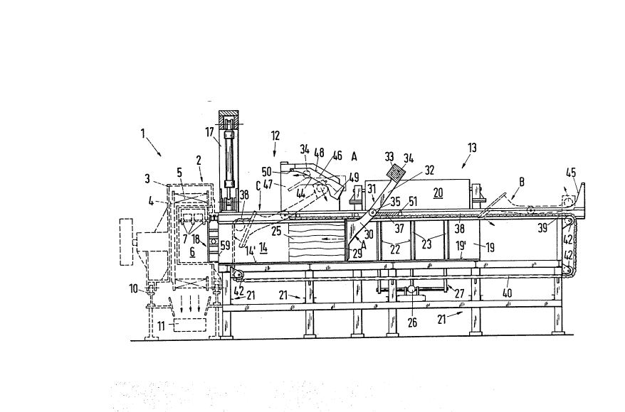
Flaking station 1, which in Figs. 1 and 2 is indicated by
broken lines, comprises essentially a flaking machine 2, in
whose housing 3 is suspended a cutting rotor 4 to which the
flaking knives are attached in the form of a ring. Knife ring
5 is enclosed by a flaking chamber 6, into which pressure
elements 7 extend. Flaking machine 2 is, together with its
drive motor 8, mounted on top of a platform 9 that can be slid
back and forth upon tracks lO. In this arrangement, the wood
sections occupying flaking chamber 6 are reduced to flakes by
the movement of flaking chamber 6 in the direction indicated
in Fig. 2 by the arrows, whereafter flaking chamber 6 returns
quickly in the opposite direction so that it can resume its
flaking function. The uniform flakes thus produced drop from
housing 3 onto a conveyor belt 11, and are thereupon delivered
directly to further industrial processing.
Flaking machine 2, which is indicated in rough outline ~-
and does not form part of the actual proposed invention, is a
so-called knife-ring type flaker. However, the proposed
design for a feed device, which shall next be disclosed in
greater detail, can also be employed in conjunction with other
types of flaking machines -- namely the knife head or knife-
disc type flaker.
The proposed feed device comprises essentially a feed
station 12 and a loading station 13. The main component of
feed station 12 is a feed trough 14, which, with its floor
surface 14' opens into flaking chamber 6 of flaking machine 2 -
at the same height and features by the shape of its side walls
15, 16 a cross sectional profile substantially corresponding
to the profile of the open flaking chamber 6. To this end,
side wall 15 features, given respect to the special shape of
the knife-ring flaker being used in the present example, a
convex bulge whose curvature corresponds to the inner radius
of knife ring 5. Above the discharge zone of feed trough 14
:
201~0~
is a pressing assembly 17 which, acting from above, serves,
during the individual flaking cycles, to immobilize the log
pile immediately in front of flaking chamber 6. A further
component of feed station 12 is a sliding closer 18 which can
be slid from the side between feed trough 14 and flaking
chamber 6, and is thus able to close flaking chamber 6 while
the last section of a given pile is being reduced to flakes.
Loading station 13, arranged immediately behind feed
station 12, comprises a loading magazine 19 and a transverse
conveyor 20 feeding thereinto. Since the cross section of
loading magazine 19 congrues with that of feed trough 14, the
former such magazine constitutes with its lateral walls 15',
16' and floor surface 19' a rear extension of such trough.
Both feed trough 14 and loading magazine 19 are mounted upon a
common frame 21.
Provided in lateral walls 15', 16' of loading magazine 19
are a plurality of slots 22 into which directing-and-righting
elements 23, 24 can be moved from the side into loading
magazine 19. Such elements serve to marshall the logs, which
have fallen from transverse conveyor 20 into loading magazine
- 19, into a tightly packed, parallel log pile 25. Control-
and-righting elements 23, 24 can, by means of control rods 27,
2~, be actuated by hydraulic assemblies 26.
A single common pushing plate 29 can be longitudinally
slid along feed trough 14 of feed station 12 and loading
magazine 19 of loading station 13, in order to push log pile
25, which has been formed inside loading magazine 19, firstly
into feed trough 14 and from thence cyclically in uniform
sections into flaking chamber 6 of flaking machine 2. In this
arrangement, as has been more fully disclosed in United States
patent referred to above, the individual advance cycles of the
log pile can, in accordance with the longest log in a given
pile, be adapted in their number and duration to the cutting
width of the flaker, so that when flaking chamber 6 has been
thus optimally loaded, pile sections of equal length can be
processed. This prevents the occurrence, following the last
flaking cycle of a given log pile, of leftover log pieces.
- ~ . - : ~ ... . .. - . - . . .. . ..
20~ 5Q3~
Fig. 1 shows pushing plate 29 in three positions, i.e. in
pushing position A, and, as indicated by the broken lines,
withdrawal position B and midpoint C during tipping. Pushing
plate 29 is attached to three arms 30 of a double-armed lever
system 31, to whose other arms 32 are attached a counterweight
33 as well as a pair of control rollers 34 arranged on either
side of such counterweight. Double-armed lever system 31 is
borne on a slewing axle 35, which itself sits in an
essentially flat plate which, together with lateral rollers
36, form a support 37 that can be moved back and forth in
guide grooves 38 that run along the top of both feed trough 14
and loading magazine 19.
Guide grooves 38 extend from feed trough 14 through
loading magazine 19 and beyond. The reciprocal travel of
support 37 is induced by a chain drive comprising two endless,
synchronously driven lengths of chain 39, whose upper length
is also housed in guide grooves 38, while the lower length
slides along in chain grooves 40, which are attached to the
inner side of frame 21. Redirection of both chain lengths 39
is effected by paired chain wheels 42, of which one pair,
being connected together by a shaft 41, moves in concert with
each other and can be driven by means of a controllable
mechanical or hydraulic motor 43.
Guide rollers 34 of pushing plate 29 interact for a short
time with stationary control paths 44, 45, which are,
respectively, arranged in pairs on both sides of the outlet
zone of feed trough 14 and at a distance behind loading
magazine 19. Both control paths 44 located on top of feed
trough 14 are formed by the underside of a guide tongue 46,
which is slewably borne on the inner side of lateral cheeks
47, which themselves are attached to the lateral edges of feed
trough 14. The upper side of both guide tongues 46 form
running surfaces 48 for guide rollers 34, which, when pushing
plate 29 is in the pushing position A, press down far enough
so as to be able to pass unhindered in the direction in which
the logs are to be fed to the flaking machine. Next, guide
tongues 46, under the influence of counterweight 49 attached
i . . . .. . .. . . ~ , ... . - . .. - .. .. . . . .. . . . . . .
20~38
thereto, return to their original position, which is
determined by a stop 50 located on both lateral cheeks 47.
Thus repositioned, guide tongues 46 are able, after the start
of the return trip of pushing plate 29, to provide the impulse
for pushing plate 29 to regain its withdrawal position s.
After pushing plate 29 has been swung back into its withdrawal
position B, one of lever arms 32 of double-armed lever system
31, which bear counterweight 33, comes to rest upon an elastic
buffer 51 attached to support 37, whereupon it is able to lie
during the entire return trip of pushing plate 29.
The other stationary control path 45, located at the
opposite end of the proposed feed device, at a distance from
loading magazine 19, serves to cause pushing plate 29 to slew
back into its pushing position A behind log pile 25, which has
been prepared inside loading magazine 19.
Sliding closer 18, provided between the discharge end of
feed trough 14 and flaking chamber 6, is shown in Figs 1 and 2
as being closed and in Fig. 4 as being open.
Sliding closer 18 is capable, after the last section of a
log pile has been fed into the flaking chamber, of locking
flaking chamber 6 so that pushing plate 29 can quickly regain
its starting position without occasioning, during flaking of
the last section of a log pile, the pushing of logs from
flaking chamber 6 into feed trough 14, a condition that could
lead to the creation of left over log sections and the
concomitant deterioration of flake quality.
As Fig. 4 in particular demonstrates, sliding closer 18
can be slid from the side between feed trough 14 and flaking
chamber 6. To this end, sliding closer 18 is suspended on
track rollers 52 and is laterally guided from the bottom in a
groove 53 provided in the floor of flaking chamber 6. Track
rollers 52 run upon a guide rail 54 that is attached to a
flange 55 that itself is horizontally attached to housing 3 of
flaking machine 2. For the purposes of the intended
operation, guide rail 54 follows the reciprocal movement of
flaking machine 2, while sliding closer 18, which is slidably
suspended thereupon, remains immobile. Sliding closer 18 is
2 0 .~ cJJ ~
actuated rather, by means of a hydraulic system 56 borne upon
a bracket bearing 57 which is itself attached to a boom 58
attached to frame 21. Immediately after the last section of
any given log pile has been fed into the flaking chamber,
sliding closer 18 closes flaking chamber 6. Sliding closer 18
also acts, during the preceding flaking sequences, as a
pressure element, which with its reinforced frontal face 60
acts together with the opposing lateral wall 15 of feed trough
14 to hold the logs in place from the side immediately in
front of the flaking chamber. Accordingly, frontal face 60 is
concavely shaped to fit the convex curvature of lateral wall
15 of feed trough 14. Additionally, frontal face 60 is
provided with an oblique surface 61 that faces flaking chamber
6, in order to ensure proper closing of sliding closer 18.
Sliding closer 18 in its closed condition finally serves,
through its protective metal cladding 59, as a stop for log
pile ~35 that has been newly slid into feed trough 14. Thus,
sliding closer 18 marks the point from which pushing plate 29
can begin feeding, in cycles of uniform duration, the logs -
into the flaking chamber. Simultaneously, the closing of
sliding closer 18 sends a signal to transverse conveyor 20 to
recommence loading magazine 19.
Fig. 5 demonstrates the kinematic operating principle
behind the mechanism that controls the slewing movements of
pushing plate 29 from pushing position A into withdrawal
position B and vice-versa. It is proposed that the masses
both of pushing plate 29 and of counterweight 33 be such, and
so positioned relative to the slewing axis 35 of double-armed
lever system 31 so positioned, that, when lever system 31
assumes mid-position C of the slewing angle ~ the total centre
of gravity tmass centre point) S of such double-armed lever
system 31 is situated exactly above slewing axis 35. In mid-
position C, double-armed lever system 31 thus assumes an
unstable equilibrium, from which pushing plate 29 is then able
to tip of its own accord into one of either stable positions A
or B, in which centre of gravity S takes up position S' or S"
respectively. The redirection of pushing plate 29 thus
2~1 5V~
13
requires only that the integral mass of such double-ar~ed
lever system 31 as concentrated at centre of gravity S be
caused, by control impulses impinging, via stationary control
paths 44, 45 upon guide rollers 34, to be shifted by the
height difference h, whereafter pushing plate 29 slews back
into either stable pushing position A or withdrawal position
B.
The proposed design for a feed device operates as
follows:
Wooden logs, whose individual transported length is
approx. 2.5m, are transported from (not illustrated)
conveyance systems to transverse conveyor 20, which transports
such logs one by one into loading magazine 19. Inside the
latter, the logs are, by means of suitable intervention of the
directing-and-righting elements 23, 24, formed into compact,
parallel log piles 25. As soon as loading magazine 19 has
been filled to its optimal operating level, which, for
example, can be signalled by means of an electronic light
panel, transverse conveyor 20 is stopped and directing-and-
righting elements 23, 24 withdrawn entirely from loadingmagazine 19. Meanwhile, pushing plate 29 has advanced the
last section of the preceding log pile into flaking chamber 6,
and is, following closure by sliding closer 18 of flaking
chamber 6, swung back into its withdrawal position B to
rapidly return to its starting position behind loading
magazine 19.
At the end of the return trip, pushing plate 29 is again
lowered by stationary control paths 45 into its pushing
position A, in which it is able, by advancing again, to push
the log pile 25, already prepared inside loading magazine 19,
into feed trough 14 up to the stop at the forward end of such
feed trough, sliding closer 18 being still in its closed
condition. The halting point for the advance movement of
pushing plate and log pile, which is created by the closure of
sliding closer 18, marks for pushing plate 29 the starting
point, from which the latter can then push, in cycles of
uniform duration, log piles 25 into flaking chamber 6.
2 0 ~ 8
1"
Simultaneously, transverse conveyor 20 is signalled to resume
filling loading magazine 19.
Following the advance of each section of log pile 25 into
flaking chamber 6, both the hydraulic systems of pressure
assembly 17, which presses down from the top, and sliding
closer 18, which presses in from the side, are activated, and,
after a predetermined pressure level has been reached, flakiny
machine 2 is caused to move in the direction indicated in Fig.
2 by the arrow, whereby the constantly rotating knife ring 5
is able to reduce to wood flakes the logs held in flaking -
chamber 6. Following this step, flaking machine 2 is quickly
moved back into its starting position and, after pressure
assembly 17 and sliding closer 18 have withdrawn their
pressure, flaking chamber 6 is again fed with logs. After the
last section has been fed from the log pile into the flaking
chamber, sliding closer 18 is slid in front of flaking chamber
6 whereupon pushing plate 29 is immediately swung back into
its withdrawal position B to quickly move back into its
starting position behind the loading magazine.
While log pile 25 is being rendered into wood flakes,
loading magazine 19 is again filled with the next log pile 25,
in order to enable the operating cycle to recommence in the
manner described above.
As has already been mentioned, the mode of functioning of
the proposed feed device is not changed by the type of flaking
machine it serves to feed with logs. In place of the knife-
ring flaker described in the present application, a knife-
head type flaker or a knife-disc flaker can be employed,
whereby in the case of the latter example, the only
modification to be made to the proposed feed device would be
that of providing both pushing plate 29 and sliding closer 18 -
with a concave bulge corresponding to the radius of the knife-
disc.