Note: Descriptions are shown in the official language in which they were submitted.
2~15~6
BACKGROUND OF THE INVENTION
1. Technical Field
The present invention generally relates to a drive bit
for driving a screw or bolt. More specifically, this
invention relates to a drive bit suitable for gripping a -
screw or bolt through non-magnetic means. Class 81,
Subclass 436, Screw Driver Implement, United States Patent
Office Classification, appears to be the applicable general
area of art to which the subject matter similar to this
invention has been classified in the past.
2. Background Information
Drive bits are extensively used with socket drives for
driving threaded screws and bolts. The simple interchange-
ability of the drive bits lends their use to a large variety
of screw and bolt forms and sizes. However, a shortcoming
with drive bits, as with all forms of screw drivers, is
their inability to firmly retain the screw on the end of the
bit. This is a desirable feature when the location that the
screw is to be installed precludes the use of the user's
hands or other means for holding the screw until the screw
threads have sufficiently engaged the receiving body. One ~ -
solution has been to use a magnetized drive bit to provide
retention between the drive bit and screw. However, the use
of a magnetized drive bit is also at times precluded when
working around magnetic-sensitive equipment or when driving
non-magnetic screws such as those formed from aluminum.
There have been devices proposed ior non-magnetically
. ~ -,-,.
?' ~
2--
retaining conventlonal slotted screws through the use o~
drivers that grip the slotted screw head recess. An example
of this type of retention means is U.S. patent No. 3,224,479
to Osborn et al. However, the Osborn device lends itself to
the retention of slotted screws only and does not address
many other types of screw head recess forms in use today.
Examples of significance to the present invention are the
Robertson, the TORX, and the hexagonal types of screw head
recess forms. The three forms presented here are all
characterized by relatively large screw head recesses as
viewed from the screw's longitudinal axis. The Robertson
form is substantially that of a square. The TORX form is
substantially he~agonal with arcuate smoothly contoured
concave sides and convex points. The hexagonal form takes
its name literally from its geometric shape. Because of the
dissimilar and unique screw head recess forms of each, the
non-magnetic retention means offered by the current state of
the art is impractical. Therefore, what is needed is a
drive bit having non-magnetic retention means for screw head
recess forms such as the Robertson, TORX, and hexagonal that
can effectively and firmly grip the screw until sufficiently
engaged in the receiving body.
SUMMARY OF THE INVENTION
It is an object of the present invention to provide a
drive bit with means for retaining Robertson, TORX, and
hexagonal screws.
It is a further object of this invention that such
drive bit provide non-magnetic retention means for use
around magnetic-sensitive equipment and for use with non-
magnetic screw materials, such as aluminum.
Lastly, it is an object of this invention to provide adrive bit comprised of two members whose retention means is
a grlpping action that is derived from the relative motion
between the two members while engaged within the screw head
recess.
In accordance with the preferred embodiment of this
invention, these and other objects and advantages are
:
. . . : : . , , - , . -, . , :, , " , :
2~15~
accomplished as follows.
According to the present invention there is provided a
gripping drive bit which is adapted for use with a
Robertson, TORX, or hexagonal screw. The drive bit com-
prises two members. The first member is substantially
elongated in shape and has a driving end, an oppositely
disposed driven end, and a substantially planar surface that
runs it longitudinal length. The second member is also
substantially elongated in shape and correspondingly has a
driving end, a driven end, and a substantially planar
surface that runs its longitudinal length. The first and
second members are complementary and mate along their planar
surfaces so that their respective driving ends and driven
ends mate accordingly to form composite driving and driven
ends, respectively. The composite driving end is of p~per
form and size for engaging a conventional Robertson, TORX,
or hexagonal screw head recess. The composite driven end,
located opposite to the driving end, is of such form to
engage a conventional socket drive, preferably a hexagonal
socket drive. Notches for receiving the retaining ring of a
socket drive so equipped are provided substantially adjacent
to the composite driven end. The planar surfaces of the two
members are defined by a longitudinal plane which is at an
acute angle with the rotational axis or longitudinal center
line of the composite bit, and which also passes through the -
approximate center of the composite driving end. The -
longitudinal plane also forms a second acute angle, with a
diametral center line or straight line passing from side to
side of the composite driving end through said rotational
axis, that bisects a driving point or lobe of the particular
screw head recess form.
According to a preferred aspect of this invention, the
means i'or retaining the screw or bolt on the driving end of
the drive bit is provided when the composite driving end
becomes misaligned after a minimal amount of torque has been
exerted on the screw by the drive bit. The misalignment is
created when the two mating members of the composite drive
bit forcibly slip along their respective planar surfaces as
,' ' .' . ;".,, ," " ',,,''' " '"'' ' '' " '' ':.' ' .' .''-,',''.' "' , I '. .'. ' ' ' ' " : ' '
2 0 1 ~
a result of the applied torque. The individual driving ends
of the bit members are forced along the grades provided by
the acute angles of the longitudinal plane, each driving end
being forced in opposing diagonal directions of the particu-
lar screw head recess form. This action effectively pro-
vides for securely gripping a Robertson, TORX, or hexagonal
screw or bolt under most practical conditions without the
need for a magnetized drive bit.
A significant advantage of the disclosed invention is
the non-magnetic means for retaining screws on the driving
end of the drive bit, allowing the driver to be used with
non-magnetic screws or in environments that are sensitive to
magnets and their accompanying magnetic fields. Another
advantage is that the drive bit can be used with a conven-
tional socket drive and is specifically formed to drive a
Robertson, TORX, or hexagonal screw or bolt, each type
having a unique screw head retention form.
Other objects and advantages of this invention will be
better appreciated after a detailed description thereof
which follows.
BRIEF DESCRIPTION OF THE DRAWINGS
Figure 1 is an exploded view of a composite gripping
drive bit for use with a Robertson screw or bolt in
accordance with a preferred embodiment of this invention. ~-
Figure 2 is an end view of the driving end of the
composite gripping drive bit i'or use with a Robertson screw
or bolt as shown in Figure 1.
Figure 3 is a partial side view of a composite gripping
drive bit engaged with a Robertson screw in accordance with
a pre~erred embodiment of this invention.
Figure 4 is a side view o~ a composite gripping drive
bit in accordance with a preferred embodiment of this inven~
tion which is installed in a conventional screw driver with
a hexagonal socket.
Figure 5 is a cross sectional view of the composite
gripping drive bit ior use with a Robertson screw as shown
in Figure 3 illustrating the relationship o~ the individual
: , .
f~ O ~ ~
driving ends of the two members when engaged with and
gripping the screw head recess o~ a Robertson screw.
Figure 6 is an end view of the driving end of a
composite drive bit for use with a TORX screw or bolt.
Figure 7 is a cross sectional view of a composite
gripping drive bit for use with a TORX screw showing the
relationship o~ the individual driving ends of the two
members when engaged with and gripping the screw head recess
of a TORX screw.
~igure 8 is an end view of the driving end of a compos-
ite gripping drive bit for use with a hexagonal screw or
bolt.
Figure 9 is a cross sectional view of a composite
gripping drive bit for use with a hexagonal screw showing
the relationship of the individual driving ends of the two
members when engaged with and gripping the screw head recess
of a hexagonal screw.
DESCRIPTION OF THE PREFERRED EMBODIMENTS
In a preferred embodiment o~ this invention, the
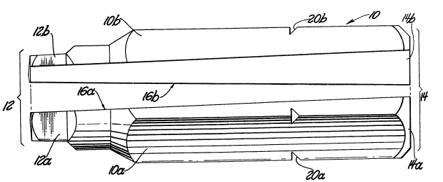
composite gripping screw drive bit 10, as shown in Figure 1,
comprises two members, 10a and 10b. Each member comprises a
driven end, 14a and 14b, disposed at one end of the member,
an oppositely disposed driving end 12a and 12b, and a
substantially planar surface 16a and 16b that runs each
member's longitudinal length interposed between driven ends
14a and 14b and driving ends 12a and 12b. The first and
second members 10a and 10b are complementary and mate along
their planar sur~aces 16a and 16b so that their respective
driving ends 12a and 12b and driven ends 14a and 14b mate
accordingly to form composite driving end 12 and composite
driven end 14, respectively. -
Planar sur~aces 16a and 16b are de~ined by a longitudi-
nal plane 18 which is at an acute angle with the longitudi-
nal center line of the composite gripping screw drive bit
10, and which also passes through the approximate center of
the composite driving end 12. Because the planar sur~aces
16a and 16b preierably pass through the composite driven end
:.. . ., ~ ., . , , ,, . , ~., , . - :
~5~
--6--
14, the maximum for this acute angle is limited by the
length and diam~ter o:E the composite gripping screw drive
bit 10.
The angle must be greater than zero degrees to enhance the
motive force between members lOa and lOb, but preferably
less than approximately 10 degrees.
Where longitudinal plane 18 passes through the approxi-
mate center of composite driving end 12, a second acute
angle is formed with a diametral center line that bisects a
driving feature of the composite driving end 12. Drive
features are defined for purposes of the present invention
as the projections on the composite driving end 12 which
correspond to the projected internal features of the screw
head recess of the screw or bolt, and that provide the
physical contact for the transfer of rotational motion and
torque between the composite driving end 12 and the screw
head recess. The second acute angle has a preferred angular
range of greater than about 5 degrees but less than about 40 - -
degrees. There is no specifically preferred angle since the
relative slippage between the driving ends 12a and 12b
requires only that the longitudinal plane 18 does not bisect
a driving feature of composite driving end 12. The second
acute angle must be of sufficient magnitude to promote rela-
tive slippage between the driving ends 12a and 12b, but at ~ -
the same time it is limited by the angular positions of the
drive features of the particular drive form. The composite
gripping screw drive bit members lOa and lOb are unsymmetri-
cal as a result of their planar surfaces being defined by
the first and second acute angles.
Disposed around circumference of the composite gripping
screw drive bit 10 there may be retaining notches 20a and
20b for engaging the retaining ring o~' a socket drive so
equipped. The retaining notches are substantially adjacent
to the driven end and assist in retaining the composite
gripping screw drive bit within a socket drive during use.
Alternatively, composite gripping screw drive bit 10 may be
retained magnetically within a socket drive if the gripping
screw drive bit 10 is formed from an appropriate magnetic
. :.,
' " ''"'.:
2 ~ 5 ~ .
material.
In ~igure 2 an end view of the driving end 12 of com-
posite gripping screw drive bit 10 illustrates the Robertson
form 22 for use with a Robertson screw or bolt and depicts a
drive feature 23 for Robertson drive form 22 as being a
corner of the substantially square Robertson drive form 22.
The Robertson drive form 22 therefore has four drive
features ~3 corresponding to the four projections of the
square Robertson form 22. The number of drive features
corresponds to the particular drive form of the composite
gripping screw drive bit 10.
The composite driven end 14 is illustrated throughout
the Figures as being of hexagonal form for engaging a
conventional hexagonal socket drive. It is well known in
the art that there is a wide range of socket drive forms and
sizes available. It can readily be seen that the composite
driven end 14 of the present invention can be of any such
form as to engage the various socket drive forms available
and therefore is not limited to the hexagonal form illus-
trated.
Figure 3 illustrates the engagement of the compositedriving end 12 of the composite gripping screw bit 10 with
the screw head recess of a conventional screw 28 having an
appropriate screw head recess, such as Robertson, TORX, or
hexagonal type.
Figure 4 illustrates the engagement of the composite -
gripping screw drive bit with a conventional hexagonal
socket drive 36 for illustrative purposes only. The
hexagonal socket drive 36 is mounted on the end of the drive
shank 34 of a conventional screw driver handle 30. A
retaining ring 32 is illustrated as being disposed within
the hexagonal socket drive 36 and engaged with the retaining
notches 20 of composite gripping screw drive bit 10. When
the user engages the composite driving end 12 with a screw
head recess, as shown in Figure 3, and applies sufficient
rotational torque through handle 30, misalignment of the
compsite driving end 12 occurs through the interaction of
the drive bit members lOa and lOb along their planar
2~15~
-~3-
surfaces 16a and 16b.
Figure 5 illustrates the result of the composite
driving end 12 misalignment within a screw head recess
having the Robertson form 22. The means for retaining the
screw 28 on the composite driving end 12 of the composite
gripping screw drive bit 10 is provided when the member
driving ends 12a and 12b become misaligned after a minimal
amount of torque has been exerted. The misalignment is
created when the two mating members lOa and lOb of the
composite gripping screw drive bit 10 forcibly slip along
their respective planar surfaces 16a and 16b as a result of
the applied torque. The individual driving ends 12a and 12b
of the bit members lOa and lOb are forced along the grades
provided by the first and second acute angles oi the longi-
tudinal plane 18, each driving end 12a and 12b being forced
in opposing diagonal directions within the Robertson screw
head recess form 22, from their positions shown in Figure 2
to their positions shown in Figure 5. That is, the driving
ends 12a and 12b are forced outward in two directions from
2G their initial positions in Figure 3 into their gripping
positions, shown in Figure 5, against the adjacent wall
surface of the screw head recess form 22. This action
e~fectively provides for securely gripping the Robertson
screw 28 without the need for a nagnetixed drive bit.
In Figure 6 an end view of the mated driving ends 112a
and 112b defined by longitudinal plane 118 of an alterna-
tive, but equally preferred, composite gripping bit 110 is
illustrated of the TORX drive form 24 for use with a TORX
screw or bolt. The TORX drive form 24 is substantially
hexagonal with arcuate smoothly contoured concave sides and
convex points. Drive feature 25 for a TORX drive form 24 is
depicted as being a projection o~ the substantially hexagon-
al TORX drive ~orm 24. The TORX drive form 24 accordingly
has ~ix drive ~eatures corresponding to the six projections.
Longitudinal plane 118 does not bisect a drive feature 25 of
the TORX drive ~orm 24, thus providing a nonsymmetrical
mating of the member driving ends 112a and 112b.
Figure 7 illustrates the misalignment of member driving
'
2~1~0~iG
ends 112a and 112b within a screw head recess having the
TORX driv0 form 24. The means for retaining the screw 28 on
the composite driving end 112 of the composite gripping bit
110 is fundamentally the same as for the Robertson form.
Members 110a and llOb are provided which mate along a longi-
tudinal planar surface defined similarly by a first and
second acute angle. The member driving ends 112a and 112b
of the individual bit members 110a and 110b are forced along
the grades provided by the acute angles of the longitudinal
plane 118, each driving end 112a and 112b being forced in
opposing diagonal directions within the TORX screw head
recess form 24. This action effectively provides for
securely gripping the screw 28 under most practical condi-
tions without the need for a magnetized drive bit.
Figure 8 illustrates another alternative, yet preferred
embodiment, for use with a hexagonal screw head recess. An
end view of mated driving ends 212a and 212b which are
defined by longitudinal plane 218 of composite gripping bit
210 illustrates the hexagonal drive form 26 for use with a
hexagonal screw or bolt and depicts a drive feature 27 for a
hexagonal drive form 26 as being a projection of the
substantially hexagonal drive form 26. The hexagonal drive
form 26, accordingly, has six drive features 27 correspond-
ingly to the six projections. Longitudinal plane 218 does
not bisect a drive feature 27 of the hexagonal drive form
26 J thus providing a nonsymmetrical mating of the member
driving ends 212a and 212b.
Figure g illustrates the misalignment of member driving
ends 212a and 212b within a screw head recess having the
hexagonal drive form 26. The means for retaining the screw
28 on the composite driving end 212 of the composite grip-
ping bit 210 is fundamentally the same as ~or the Robertson
and TORX forms. The member driving ends 212a and 212b of
the bit members 210a and 210b are forced along the grades
provided by the acute angles of the longitudinal plane 218,
each driving end 212a and 212b being ~orced in opposing
diagonal directions within the hexagonal screw head recess
form 26. This action effectively provides for securely
,, ,,,,,, , . , .. .. . .. - . . . .
2als~
--10--
gripping the screw 28 under most practical conditions with-
out the need for a magnetiæed drive bit.
In the preferred embodiment, a significant advantage of
composite gripping screw drive bit 10 is the non-magnetic
means for retaining screws on the composite driving end 12,
allowing its use with non-magnetic screws or in environments
that are sensitive to magnets and their accompanying
magnetic fields. Another advantage is that the composite
gripping screw drive bit 10 can be used with a conventional
socket drive, such as hexagonal socket drive 36, and is
specifically formed to drive screws or bolts having a screw
head recess with the shape of a Robertson form 22, a TORX
form 24, or a hexagonal form 26.
While the invention has been described in terms of a
preferred embodiment, it is apparent that other forms could
be adopted by one skilled in the art. Accordingly, the
scope of the invention is to be limited only by the
-following claims.