Note: Descriptions are shown in the official language in which they were submitted.
2olsl7l
METHOD AND APPARATUS FCR I~PROVED TIRE UNIFORMTTY
Backqround Of The ~nvention
This invention relates to the processing
of tires for unifor~-ty correction and, more
particularly, to methods and apparatus for testing tires
for force variation in which special function waveforms
are generated including an optimum grind waveform and in
which the grinding is predictive and adaptive.
Description Of The Background Art
In the art of manufacturing pneumatic
tires, various components such as belts, beads, liners,
treads, piles of rubberized cords, and the like are
sequentially assembled. During the assembling process,
structural non-uniformities may occur. When such non-
uniformities are of sufficient magnitude, they will cause
force variations on a surface, such as a road, against
which the tires roll. As a result, vibrational and
acoustical disturbances in the vehicle are created in the
vehicle upon which the tires are mounted.
Force variations are ~no~l ies which
result from "hard" and/cr ~soft" spots in the tires
2 2015171
caused by struct~'al non-uniC3rmities such as
inconsistent w211 thi_knesses, ply turn up variations,
bead sets, ply arransement and other deviations.
Regardless of the cause of force variations, when such
variations exceed the acceptable minimal level, the ride
of a vehicle utilizing such tires will be adversely
affected.
Excessive radial force variations may be
eliminated or reduced to an acceptable level by
processing on a tire ur.iformity machine. Typical
examples of known tire uniformity machines are described
in the prior patent literature. In U.S. Patent Number
3,574,~73 to Rader, an inflated tire is mounted for
rotation about a vertical axis. Parallel with the first
vertical axis is a road si~ulation wheel mounted for
rotation about a second axis, parallel to the first. The
roadwheel is adapted to contact, and be rotated by, the
rotating tire. Sensors associated with a roadwheel
determine when hard spots of the tire are rotated into
contact with a road since increased force is sensed at
the roadwheel. Conversely, lower force areas or soft
spots on the tire will also be detected by the force
sensors associated with a roadwheel. The electrical
output signals from the sensors are fed through an
electronic processor which will evaluate the sensed
information to drive grinding wheels or stones into
contact with selected portions of the tread surface
2015171
of the rotating ti-.-e at ~re~etermined times and to
predetermined depths. The grinding wheels will then
grind the appropriate patches of rubber from the tire
until sufficient rubber has been removed from the hard
spots to render the tire sufficiently devoid of high
radial force variations. The result is improved tire
performance.
Each revolution of the tire contributes
to producing a composite electrical signal. The grinding
wheels are actuated to be pulsed into contact with the
tire in accordance with such signal each time a spot of
excessive hardness of the tire is adjacent the grind
wheel. In such process, the composite output signal is
compared against an acceptable standard limit to produce
a ~rind patch or pa~ches around the periphery of the
tire.
In a subsequent patent, U.S. Patent
Number 4,458,451 to Rosers, the electrical output from
the sensor is filtered electronically to generate a sine
wave representing the radial harmonic of the sensed
signals. In addition, Rogers discloses comparing the
output of the sensors, whether of the composite variety
of Rader or of the radial harmonic variety of Rogers,
against the percentage of the peak-to-peak variation in
the generated waveform. In such arrangement, the
grinding of the tire is in a single patch of an extended
length for each revolution of the tire.
- - -
4 201~171
A further patent, U.S. Patent Number
4,669,228 to Rogers discloses an additional improvement
wherein the grinders are independently mounted and
independently mova~le in response as to independent
signals from each shoulder of the tire.
As illustrated by the great number of
prior patents and commercial devices, efforts are
continuously being made in an attempt to more efficiently
correct tire non-uniformity. None of these prior art
efforts, however, suggests the present inventive
combination of method steps and component elements
arranged and configured for correcting tire tire-
uniformity wherein such non-uniformity is detected and
converted to speclal function force signals such as
partial square waves, parti~l sine waves, full sine waves
or the like. Further, none of such prior art methods and
apparatus disclose the gener.~tion of optimal waveforms by
combining special function waveforms and none of the
prior art methods and apparatus provide for adaptive and
predictive grinding methods.
Prior art methods and apparatus simply do
not provide the benefits of the present invention which
achieves its intended purposes, objectives and advantages
over the prior art through a new, useful and unobvious
combination of method steps ~nd component elements,
through no increase in the number of functioning parts,
at a reduction in operating cost, and through the
2 ~ i 11 7 1
utilization of only readily available materials and
conventional components.
Therefore, the present invention seeks to
provide an improved method of processing a tire
uniformity machine comprising the steps of sensing the
radial force variations in a tire and generating a
composite waveform corresponding to the sensed force
variations, converting the composite waveform into a
special function waveform selected from the class of
waveforms which includes filtered partial square waves
and partial sine waves as well as full sine waves,
selecting either from a table or adaptively one of the
special function waveforms and grinding of the tire in
response to the selected special function waveform.
Further this invention seeks to selectively
remove both composite or harmonic radial force
variation from tires more rapidly and more efficiently
during the uniformity correction process.
Lastly, the subject invention seeks to
render processed tires more uniform in radial force
variations and more pleasing in appearance.
The foregoing has outlined some of the more
pertinent intentions of the invention. These
intentions and advantages should be construed to be
merely illustrative of some of the more prominent
features and applications of the intended invention.
Many o~her beneficial results can be attained by
applying the disclosed invention in a different manner
or by modifying the invention within the scope of the
disclosure.
~ '
A
20115~7~
Accordingly, a fuller understanding of the invention
may be had by referring to the summary of the
invention and the detailed description of the
preferred embodiment in addition to the scope of the
invention defined by the claims taken in conjunction
with the accompanying drawings.
SUMMARY OF THE INVENTION
The present invention is defined by the
appended claims with the specific embodiment shown in
the attached drawings. For the purposes of
summarizing the invention, the invention may be
incorporated into an improved method of processing a
tire comprising the steps of sensing force variations
in the tire to be processed, creating a first waveform
which is a composite of the sensed force variations in
the sensed tire, separating the first waveform into a
plurality of second waveforms which are special
waveforms corresponding to intended specifications of
the tire to be processed, generating third waveforms
which are functions of the second waveforms, combining
the third waveforms into a fourth waveform; and
grinding the tire to be processed in a pattern as
determined by the fourth waveform.
In particular, the plurality of second
waveforms includes composite, first harmonic, second
harmonic through the nth harmonic, the third waveforms
include excess composite waveforms,
2015171
partial harmonic wavefor~.s, full harmonic waveforms and
180 degree sine waveforms. The method further includes
the steps of modifying at least one of the waveforms as a
function of the process results from the processing of
S prior tires. The modifying is done to the fourth
waveform. The method further includes the step of
determining the position of the tire being processed with
respect to the grinding means and off-setting at least
one of the waveforms as a function of such determined
position. The force variations being sensed are radial
force variations or may be the radial run-out induced
variations.
The invention may also be incorporated
into a method of processing a tire comprising the steps
of sensing the radial force variations in the tire to be
processed, creating a first waveform which is a composite
of the sensed force variations in the sensed tire,
separating the first waveform into a plurality of second
waveforms which are special waveforms corresponding to
int~nde~ specifications of the tire to be processed,
generating third waveforms which are functions of the
second waveforms, combining the third waveforms into a
fourth waveform, modify ng the fourth waveform as a
function of the process results from the processing of
prior tires, off-setting 211 of the waveforms as a
function of the position of the tire being processed with
respect to the grinding means; and grinding the tire to
2n ~ ~ ~ 7 ~
be processed in a pattern as is determined by the fourth
waveform.
Further, the invention may be incorporated
into an apparatus for processiny a tire comprising irl
combinatioll means to sense force variations in the
tire to be processed means to create a first wave form
which is a composite of the sellsed Lorce variations in
the sensed tire, means to separate the first waveform
into a plurality of second waveforms which are special
waveforms correspollding to il~tellded speciLications of
the tire to be processed; mealls to generate third wave
forms which are functions of the secolld waveforms,
means to combine the third waveforms into a fourth
waveform, and means to grind the tire to be processed
in a pattern as determined by the fourth waveform.
In particular the plurality of second
waveforms includes composite, first harmonic and
second harmonic through the nth harmonic. The third
waveforms include excess composite waveforms, partial
harmonic waveforms, full harmonic waveforms and 180
degree sign waveforms. The apparatus further includes
means to modify at least one of the waveforms as a
function of the process results from the processing of
prior tires and the means to modify acts upon the
fourth waveform. The apparatus further includes means
to determine the position of the tire being processed
with respect to the grinding means and means to off-
set at least one of the waveforms as a
B
20I5171
function of such ~e~er.nined position. The force
variations being sensed are radial force variations or
may be the radial r~n-out induced variations.
In addition, the invention may be
incorporated into apparatus for processing a tire
comprising in combination means for sensing radial for~e
variations in the tire to ke processçd, means for
creating a first waveform which is a composite of the
force variations in the sensed tire, means for separating
the first waveform nto a plurality of second waveforms
which are special waveforms corresponding to intended
specifications of the ti-e to be processed, means for
generating third waveforms which are functions of the
second waveforms, means for combining the third waveforms
into a fourth waveform means for modifying the fourth
waveform as a function of the process results from the
processing of prior tirPs, me.~ns for determining the
positioning of the tire being processed with respect to
the grinding means and off-setting all of the waveforms
as a function of such determined position, and grinding
the tire to be processed in a pattern as deter~ined by
the fourth waveform.
Lastly, the in~ention may be incorporated
into a method of proc2ssir.g a rotating tire comprising
the steps of sensing force variations in the rotating
tire to be processed, creating an initial waveform which
is a composite of the sensed force variations in the
2015171
rotating tire, separ~ting the initial waveform into a
plurality of inte~ediate waveforms, processing at least
some of the intermedi~te waveforms, combining the
proposed waveforms into a fin~l waveform, and grinding
the rotating tire to be processed in a pattern as
determined by the final waveform.
The foregoing has outlined rather broadly
the more pertinent and important features of the present
invention in order th~t the detailed description of the
invention that follows may be better understood so that
the present contrib~tion to the art can be more fully
appreciated. Additioral features of the invention will
be described hereinafter which form the subject of the
claims of the invention. It should be appreciated by
those skilled in the art tnat the conception and the
disclosed specific embodiment may be readily utilized as
a basis for modifying or desisning other structures for
carrying out the same purposes of the present invention.
It should also be realized by those skilled in the art
that such equivalent constructions do not depart from the
spirit and scope of the invention as set forth in the
appended claims.
BRIEF DESCRIPTION OF THE DRAWINGS
For a fuller underst~n~ing of the nature
and objects and advantages of the present invention,
reference should be had to the following detailed
11 2015171
description taken n conjunc~ion with the accompanying
drawings in which:
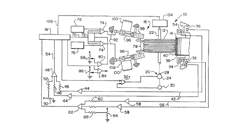
Figure 1 s a schematic illustration of a
tire uniformity machine for detecting, measuring and
reducing force variations in a pneumatic tire.
Figure 2 is an electrical diagram
illustrating certain details of the electronic processor.
Figure 3 is a diagrammatic view of a
preferred electronic processor for use in the machinery
of Figure 1.
Figure 4 is an electrical block diagram
of the special function force correction means and
special function generator.
Figure S is a graph of the 180 degree
grind mode.
Figure 6 is a graph of the square wave of
the Fourier expansion of the 180 degree square wave.
Figure 7 is a half sine wave grind
function.
Figure 8 is a graph of a full sine wave
grind function.
Figures 9A, 9B, 9C and 9D are block
diagrams of the computer program for adaptive offset
grinding.
Figure 10 is a graph of a radial
composite peak-to-peak force.
- - .
2015171
12
Figures 11 ar.d 12 are graphs of the force
removed during cne grind versus the desired force removal
in pounds.
Figures 13 and 14 are the force le~.oved
and force ~ -ved per grind regression factor measured
against the desired force removal.
Figure 15 illustrates graphs for
generating an optimal grind function waveform.
Figure 16 is a repetitive composite
waveform describing the rur.out and illustrating the high
and low points for use in predictive first harmonic
reduction.
Figures 17 and 18 are a series of grind
waveforms showing ~he different force problems on a tire.
SLmilar referenced characters refer to
similar parts throughout the several Figures.
DETATT.~ DESCRIPTION OF TXE INVENTION
Overview
In ~igure l, there is shown by schematic
representation a tire uniformity machine 10 which
operates to reduce radial force variations in a pneumatic
tire 12 in a more efficient ~ner than was previously
possible. The tire uniformity machine 10 includes a
detection assembly 14 to sense and measure force
variations in a tire, a rubber removal assembly 16 to
remove rubber from th~ tire 12, an electronic processor
18 to process signals received from the detection
13 2 01 5 1 7
assembly and a motor 0 for rotating the pneumatic tire.
The motor 20 includes a rim upon which the tire is
mounted. The rim is carried on a spindle 22 turned by a
rotary drive means 24.
The assembly 14 to detect and measure
radial force variations in the tire includes a pair of
load cells 34 and 36 and a loadwheel 38. The loadwheel
has a cylindrical surface 40 upon which the tire 12
rotates for imparting rotation to the loadwheel. The
loadwheel is adapted for free rotation about a non-
rotating axle spaced from, but parallel with, the axis of
rotation of the tire. The axle upon which the loadwheel
38 rotates is adjustably mounted so that it may be
positioned closer to, or farther from, the axis of
rotation of the tire. In this manner, a predetermined
deflecting load ~ay be set up against the tire 12 by the
surface 40 of the loadwheel 38.
Operatively coupled to the loadwheel 38
is the pair of load cells 34 and 36 which contain sensors
such as strain gauges for measuring the forces exerted on
the loadwheel by the rotating tire in both the radial and
lateral directions. The load cells 34 convert the radial
force variation measurements to electrical signals such
as voltage level signals which are fed via lines 42
through the electronic processor 18.
During the sensing phase, the electronic
processor 18 receives, processes and interprets the
14 2015171
radial force variation slgnzlc, and stores the
interpreted signals i~. its memory. Later, during the
grinding phase, the electronic processor 18 produces a
control signal for controlling the grinding of the tire
as a function of the stored radial and lateral force
variation signals. The electronic processor will be
described in greater detail hereinafter.
The output of the electronic processor 18
includes a control sisnal cn line 70 which is sent to a
nodal point 72. There the s-gnal is divided into two
control signals. The two control signals are fed into
servo amplifiers 74 whe-ein th~y are each summed with
signals from skim sensors 75 which measure and control
the non-grinding dist~nce between the grinding wheels 78
an the shoulders of the tire 12.
The sk- sensors may be conventional
paddles which push aga nst the tire during the sensing
phase. When the tire gets larger in diameter due to
excessive force var ations, the tire pushes out the
adjacent paddle which, in turn, generates a signal to
servo amplifiers 74 to move the grinders to positions
toward or away from the tire being ground. The paddles
are located on the shoulders of the tire immediately in
front of the grinders or on the center ribs or full face
of the tire as applicable.
A signal from the electronic processor 18
also passes through line 82 to a grind classifier 80 and
201~
to a scrap classifler 8~ scrap limit potentiometer 86
establishes a preseiected value for a maximum limit
detection so that if the electronic processor signal
exceeds the preselected value, the tire will be
considered non-correctable, no grinding will occur and
the tire will be dismounted from the tire uniformity
machine 10. If the tire is not non-correctable, the
grind classifier 80 will compare the signal with a
voltage from a grind limit potentiometer 88 to determine
whether additional grinding is required. If the tire is
at or below the minimum level and no additional grinding
is required, the signal of line 90 is summed in the servo
amplifiers 74 effecting retraction of the grinding wheels
78. If the measured radial force value of the tire is
between the uppe= and iower lLmits, the signal summed in
the servo amplifier~ 7~ is converted to a hydraulic
control signal. Su5h hydraulic control signal is passed
through lines 92 to the rubber removing means 16 which is
typically comprised cf the two grinders 96.
The two grinders 96 include frames 98
which support electric motors 100, hydraulic systems 102
and grinding wheels 78. The frames 98 are pivotably
mounted on the fi.ced portions of the machine 10 with
suitable devices such as pins to allow for each grinder
98 to pivot tOward o_ away from the shoulder of the tire
10 .
2015171
16
The electronic processor 18 also has an
input signal from the angle encoder 104 along a line 106.
The angle encoder is suit-~kly attached to the spindle 22
for determining the angular position of the tire. The
signal from the angle encoder 104 to the electronic
processor 18 coordinates the location of the grinding of
the tire and takes into account the angle difference
between where the tire touches the loadwheel 38 and where
the tire touches the grinders 96.
The tire 12 is tested for radial force
variations. The magnitude of the force variations is
detected and measured, preferably within a single
revolution. Thereafter, the electronic processor will
compare the magnitude of the peak-to-peak radial force
variations with specified g_ading levels. The electronic
processor will then decide whether a grind is necessary.
If a grind is required, the electronic processor will
signal the motor to the rubber removal means 16 to remove
selected amounts of ubber from selected regions of the
tire in a programmed manner.
The electrical signals provided to the
electronic processor 18 nclude data samples for a
complete test revolution of the tire. Each sample
represents a separate measurement of the force variation
at a different angle. A measurement of the force
variation at each degree increment of the tire is thereby
specifically referenced to an angle location by the angle
2015171
17
encoder 104. The tot~l number of samples per revolution
form a synthesized composite waveform which is fed into
the electronic processor where a preselected analysis
calculation of a cyc'ic function is performed.
A composite waveform is composed of one
or more harmonically related sine waves. The lowest
frequency is called the first harmonic. All other
harmonics are intesrally related to the first by an
integer number, i.e., 2, 3, 4, S, etc. When all such
harmonic waves are added together, a composite waveform,
the original waveform, is created. The Fourier spectrum
of a composite waveform is, thus, the amplitudes of the
first, second, third, fourth, fifth, etc. harmonics
which, when added togethe-, make up the composite
waveform. The harmonic waveforms have a specific phase
relationship with each other so that when they are added
together, their sums equal the composite.
The electronic processor also functions
to determine the first harmonic high point of force which
20 i9 calculated from the ccmposite waveform. The composite
peak-to-peak force is also c~lculated by comparison of
the sequential force measurements obtained during one or
more test revolutions.
The electronic processor 18 also compares
the harmonic peak-to-peak and the composite peak-to-peak
18 201~1 71
values calculated from a test cycle with a predetermined
acceptable grading levels. If the radial harmonic peak-
to-peak and the radial composite peak-to-peak are less
than a predetermined acceptable grading level (normally
called the first limit), no correction is needed. The
tire is satisfactory and ready for use, and it is removed
from the machine 10. If either or both the harmonic
peak-to-peak and composite peak-to-peak exceed a second
limit as determined by the scrap classifier 84 and the
scrap limit potentiometer 86, the tire has force
variations that cannot be corrected by grinding to bring
either the radial harmonic peak-to-peak or the radial
composite peak-to-peak force variations within the
predetermined acceptable range (without excessive rubber
lS removal). If the r~dial harmonic peak-to-peak force
variation and radial composite peak-to-peak force
variation fall within the acceptable grindable range of
either or both (between the first limit and the second
limit) without either exceeding the second limit, a
preselected grinding procedure is performed to reduce the
radial force variations.
The electronic processor 18 also utilizes
a grinder displacement angle which is the difference in
degrees between the loadwheel 38 and the location of the
grinders 96 and 98. At this time we are presuming a
compute machine configuration which tests at one speed
and grinds at another. In addition to the grinder
19 2015171
displacement angle, a fixed num~er of milliseconds prior
to the grind may be set which would allow for the
reduction of the speed of the rotating tire while the
electronic processor receives the signal along line 106
from the angle encoder 104. Also, a signal may be sent
from the electronic processor 18 along line 108 to the
motor driver 32 which, in turn, would allow for the
grinder to be located at the leading edge of the desired
grind patch either prior to or at the time the spindle
speed is reduced to the desired grind speed.
A grind signal is sent from the
electronic processor 18 along the line 70 to a nodal
point 72 wherein the signal is divided into two signals.
Each of the signals passes through a servo amplifier 74
wherein the signal is converted to a hydraulic signal
which is passed through lines 92 to bring the grinding
wheel(S) 78 into grinding engagement with the leading
edge of the grind patch of the tire. In the mode of
grinding, which may ~e termed composite grinding, the
grind patch consists of all parts of the tire
corresponding to angles of the tire which contain force
variation values greater than a constant value of a
calculated limit which is generally termed the suppressed
limit. In a preferred usage, radial composite
I'suppressed limit" is calculated as a fixed number of
pounds, usually from five (5) to eight (8), less than the
radial composite first limit. In like manner radial
2015171
first harmonic and sei-~nd harmonic suppressed limits are
calculated from the radial first harmonic and radial
second harmonic first limits. The amount the tire is
ground is determined by the amount that measured tire
force variation, when referenced to its soft spot, is
greater than the suppressed limit.
The electronic processor 18 is programmed
to determine a grind patch which corresponds to the
minimllm angle of tire rotation during grind. One means
~o used to attain the ml nimllm angle of rotation is to start
at the calculated rzdial soft spot and compare sequential
force variations wi~h the appropriate suppressed limit as
measured both in a clochwise and a counterclockwise
direction from the soft spot. The total angle subtended
before exceeding the s~:p~ressed limit in both directions
is termed the no-grind portion of the tire. The
remaining angular portion of the tire corresponds to the
desired grind patch which is normally 180 degrees or
less.
Upon completion of grinding the grind
patch, the grinder is withdrawn from the tire. A
determination as to zny further grinding may again be
made by retesting the tire. If no further grinding is
required, the rotating tire is stopped and the tire is
ejected from the tire ~niformity machine 10.
In ar. altPrnate method of grinding,
generally termed harmonic grir.ding, the grind output for
21 2015171
harmonic correction is cor.-trLcted in the electronic
processor and its the real timP difference between the
synthesized harmonic function and a harmonic suppressed
limit. The synthesized harmonic function is calculated
from the magnitude of the harmonic peak-to-peak force and
the phase of the harmonic force as calculated by the
Fourier methods referenced above. The grind output
calculation determines a grind patch which is of equal
lengths on both sides of the harmonic high point. The
grind patch is normally less than or equal to 180
degrees.
Furtner details of the method of
operation of couplir.g the cutput of the c-ircuitry to the
grinders is described in the aforementioned U.S. Patent
lS Number 4,669,228 to Rogers.
Elec~ronic techniques for sensing the
peak-to-peak variation of the signals and for comparing
the electrical output of the signals to the peak-to-peak
is described in the aforementioned U.S. Patent Number
4,458,451 to Rogers and Duffy. In addition, such patent
to Rogers and Duffy descrfbes the techniques for
filtering the composite signal and converting it to a
radial harmonic slgnal.
Inscfar as the mechanical description of
the sensors and grinders is concerned, such description
is essentially the sac,e as that described in the
2015171
22
aforementioned patent applications assigned to the
assignee of the present invention. According to the
present invention, however, the electronic controls which
receive the composite signal from the sensors are
S different as they are processed to create the grind
c,~ signal for use in controlling the grinders. More
specifically, the electronic controls modify the
initially generated composite signal and perform various
steps including creating (a) a first composite waveform,
(b) second wavefornls formed from the separation of the
first waveform and which are special waveforms
corresponding to the intended specifications of the tire
to be processed, and ~c) third waveforms which are
functions of the second waveform and (d) a fourth
waveform which is a combination of the third waveforms.
This is all in a mAnner which produces superior tires and
may effect the grinding with a single grind sequence
instead of the multiple sequential grind sequences as was
necessary in the prior art. This provides great economy
and savings in terms of time and money.
The control sequence described herein may
be used to modify essentially any commercially available
computer in industry today. The modifications of such
computer for effecting the intended results herein could
be done by a wide variety of programming variations. The
particular programming described herein is of a preferred
form but other forms could be utilized to effect the
23 201S171
intended results in hcccrdance with the teachings herein
of the present invention.
In accordar.ce with the present
disclosure, the radial force signals may be converted to
special function signals which may be utilized for
directing the grinding of the tire. Such special force
functions include the partial square wave, the partial
sine wave and the full sine wave.
Higher Harmonic Force Correction
Selective reduction of higher harmonic
forces or runout variation is performed by uniformity
machines using 180 degree grinding methods. The higher
harmonic filter is substituted for the first harmonic
filter and suitable delay compensations are made. With
the 180 degree grind, there is no introduction of
subharmonics.
This method is of advantage where the
match between the tire and the car is such that the
particular harmonic of the tire is troublesome. This
harmonic can be selectively eliminated with the apparatus
shown in Figure.3.
Special Function Force Correction
Special function force correction
circuitry is employed which permits the processor to
either select from a table or select adaptively either
the partial square wave, the partial sine wave, or the
full sine wave method of grinding a tire.
24 2015171
The f ul 1 S ine wave and the half sine wave
functions are respectively applicable to processes where
zero harmonic induction is required or for processes
where cosmetic grinding with m i n; mll~ rubber removal is
desired. Figure 4 shows circuitry for effecting such
results. Figure 5 is a graphical representation. In
considering higher harmonic generation with various grind
modes, the 180 degree grind only, odd harmonics are
generated and the value of the third harmonic is induced
equal to one-third the value of the first harmonic
reduction. The value of the fifth harmonic is induced
equal to one-fifth the value of the first harmonic
reduction.
Formulas for deriving such values are as
follows:
Considering higher harmonic generation
with various grind modes: In the 180 degree square wave
grind mode, the amplitude cf the harmonic content is
calculated by the formula:
n-~o
f(x) = 1/2 + (2/~r) ~ (-ln /n)sin (nfr/2)
n-l
where f(x) is the amplitude of the n th harmonic of the
180 degree square wave used to correct the tire.
The relative harmonic amplitudes from the
above formula are czlculated as:
-
2015171
~MC~IC RELATIVE AMPLITUDE
n
O .5
~ -.64
2 0
3 .21
4 0
-.13
When a 180 degree square wave is used to
remove a flln~m~ntal (n = 1) force from a tire, there are
no even harmonics induced. The amplitude of the higher
order odd harmonics that ar~ induced are inversely
proportionate to the order cf the higher harmonic. When
the removal of a first harmonic force is processed ~y
grinding with a 1~0 degree square wave, odd harmonics are
also ground into the tire creating forces which may add
or subtract from existing forces in the tire depending on
the vector relationship of the induced forces to the
forces which initiallv ex_sted in the tire.
If a 90 degree square wave is used to
remove the f~ mental force from a-tire, the amplitude
of the induced forces -s calculated from the formula:
f(x) = 1/4 + (2/rr) ~ h /n) sin (nfr/4)
n l
2015171
The relative harmonic content of the 90
degree square wave is calculated from the above formula
as:
HARMONICRELATIVE AMPLITUDE
n f(x)
0 .25
1 -.45
2 .32
3 -.15
4 0
S .09
It is seen that when a 90 degree square
wave is used to grind away the rubber of a tire with the
purpose of removing the first harmonic, a second harmonic
of almost the amplitude of the first harmonic is induced
into the tire. Again, this higher order frequency that
is induced into the tire may add or subtract from the
existing forces in the tire depending on the relative
phase between the induced force and the existing force in
the tire.
If a 270 degree square wave is used to
remove the fundamental (or first) harmonic of force from
a tire, the following formula is used to describe the
amplitude of the fre~ency content of the 270 degree~5 square wave:
f(x) = .75 + (2~1r) ~ (-1 /n) sin (3nfr/4)
n 1
27 201 Sl 7I
The relative amplitudes of the induced
harmonics as calculated fro~ the above formula for a 270
degree square wave grind correction wave form are
presented:
HI~RMONIC ~ELATIVE AMPLITUDE
n f(x)
- . 4 5
2 - . 3 2
3 - . 15
4 0
.09
Grind signals are normally phased such
that the first harmonic content of the waveform will
cancel out of the existing first harmonic content of the
15 composite waveform wh.ch is resident in the tire which is
being corrected.
With equal amounts of 90 degree grind and
270 degree grind, the second harmonic contents of the two
wave forms would cancel out and no second harmonic would
be induced.
An often used waveform for correction of
a tire is the 180 degree grind square wave. The
following analysis will describe how it is superior to
the 90 degree and the 270 degree square wave for the
25 reduction of the first harmonic from a tire.
2015171
The 180 degree sine wave is another of
the class of waveforms that are used to reduce the
fundamental waveform content of a tire.
The ~ourier expansion of the 180 degree
sine wave function is described as:
f(t) = 1/1r+ (1/2) sin wt - (2/fr) ~ (l/n -1) cos nwt
n= Z,~,6
The relative amplitudes of the induced harmonics as
calculated from the above formula for a 1/2 sine wave are
presented:
ONICRELATIVE AMPLITUDE
n f(t)
0 .32
.5
2 .21
3 0
4 .04
0
A pure sine wave used to correct the tire has the
formula:
f(t) = 1 + sin wt
The relative amplitude of the harmonic content of this
function is calculated as:
2015171
2g
HARMONIC RELATIVE ~PLITUDE
0 .5
1 .5
2 0
3 0
4 0
S O
Each of the above wave forms may be
selected by the user to perform force reduction of the
fundamental force component of a tire depending on the
requirements of the application. The first harmonic
component of the above described waveforms is phase
matched with the first ha_monic component of the
composite waveform which describes the force variation of
lS the tire. The tire is then ground on the tread shoulder
or face or a combination of the two in a manner that the
first harmonic componer.t of the ground tire cancels out
the first harmonic component of the composite of the
original tire force varlation.
The special merit of each of the grind
waveforms is described below. The operator or the
computer will select the appropriate waveform to reduce
the force depending on the criteria developed for the
processing of that tire.
2015171
he me-its ~f processing with each
waveform are presente~ in the following table and then
further discussed:
HARMONIC180 SQ.90 SQ. 270 SQ.180 SINE SINE
0 5 .25 .75 .32
4 -.45 -.45 .5
2 ~ .32 -.32 .21Q45 0
3 .2i -.15 -.15 0 0
4 0 0 0 .04@45 0
.13 .0g ~0~ ~ ~
CRITERIA
~AX 1.28 1.3 * .6 1.56
1/0
MAX
1/(0+2+3+4+5) ./5 .65 .34 .88
NO 2 X X
NO 3 X X
1/(2+3+4+5)1.83 .8 .8 2 INFINITE
MA~
l/RUBBER
REMAINING .64 .45 .45 .5 .5
2015171
31
If the criteria is to m~;mi ze the amount
of first harmonic remoqed with respect to the amount of 0
component removal, then the 90 degree square wave would
be used. This criteria may m; nim; ze the total amount of
rubber removed from the tire.
If the criteria is to m~; r; ze the amount
of first harmonic removal with respect to the sum of all
other harmonics including the 0 component, then either
180 degree sine or pure sine wave processing would be
selected.
If the criteria is to not introduce any
second harmonics during the processing, then the 180
degree square wave or the pure sine wave would be used.
This may be of advantage when tuning the tire to a
lS particular vehicle.
If the criteria is to not introduce any
third harmonics, then the 18 degree sine wave or the pure
sine wave processing would be used. This may be of
advantage when tuning the tire to a particular vehicle.
If the criteria is to m~Yirize the ratio
of first harmonic remove to that of all other
frequencies, then the 180 degree square or the 180 degree
sine or the pure sine wave method would be used to
process the tire.
If it is required to r~xiri ze the amount
of first harmonic removal to the m~imllm penetration of
32 2015171
the grinder into the tire, then the 180 degree square
wave would be used.
From the above analysis, it is seen that
each of the above waveforms has special merit when the
criteria for the force removal of the first harmonic of
force of a tire is established.
Adaptive Offset and Adaptive Gain
With regard to adaptive offset and
adaptive gain, Figures 9A, 9B, 9C and 9D are the flow
diagrams for achieving this objective to accommodate the
contemplated increase ir. content of the master control
menu. The proposed revised master control menu is as
follows:
1. Harmonic Grind Limit
2. Composite Grind Limit
3. Upper Grind Offset
4. Lower Grind Offset
5. Upper Composite Grind Gain
6. Lower Composite Grind Gain
7. Grind MA~irll~ Level
8. Polish Grind Offset
9. Harmonic Grind Gain
10. Grind Patch Width Factor
11. Grind Ramp Limit
12. Conicity Offset
13. High Point ~arker Delay
14. ~elay of Grind
33 2015171
15. Tire l~pe
16. Spindle Speed
17. D/A Output
18. A/D Radial Input
19. A/D Lateral Input
20. Digital Inputs
21. Digital Outputs
Items to change;
On 17: The computer should query?
(1) RC, (2) RH, (3) LC, or (4) LH?
On 15: The computer should query?
(1~ Small Block, (2) Small Block, or (3) Rib?
An overview of the grind process compared
with Figure 9B is as follows:
at 38, grind request;
at 3g, does the RCPP force exceed the
composite grind limit, CGL;
at 40, calculate the optimum composite
grind waveform;
at 40.1, calculate a composite grind mode
suppressed limit where CGMSL equals CGL minus 2 minus 0.2
(CPP minus CGL);
at 40.2, calculate the grind wave
required to profile the grinders into the tire. The gain
shall be one-hundred percent (100%) unless in the gain
adaptive mode;
2015171
at 41, does the RHPP force exceed the
harmonic grind limit, HGL;
at 42, calculate the optimal harmonic
grind waveform and calculate the required harmonic gain
multiplier ( HGM) required to reduce the harmonic force to
the harmonic grind limit, HGL;
at 42.1, calculate a harmonic grind mode
suppressed limit where HGMSL equals the average of
composite radial force and HGMSL equals RF divided by n;
at 42.2, calculate the harmonic grind
multiplier required to reduce the harmonic force where
HGM equals 2 (HF minus HGL) divided by HF;
at 42.3, calculate the optimal harmonic
grind waveform;
at 43, will the calculated composite
grind mode removal result in reducing the harmonic force
to the harmonic grind limit;
at 44, use CGM to perform grind;
at 45, use HGM to perform grind;
In the foregoing,
(1) RCPP is the radial composite peak-
to-peak force as shown in Figure 10.-
(2) ~CGL is the process specified
composite grind limit. This is usually one (1) or two
(2) pounds below the composite grading limit. This is to
get a conservative grind during the process, the force
removed more than exceeds required force removal.
2015171
(3) ~H~P is the calculated radial first
harmonic force CGntent of the radial composite waveform.
(~ RHGL is the process specified
harmonic grind limit . This is usually one (1) or two ( 2 )
pounds below the harmonic grading limit with the
objective of overgrinding slightly n compensate for
machine variance.
(5) HGM is the harmonic grind multiplier
used in synthesizing the opt mal harmonic grind waveform.
(6) HGSL is the harmonic grind
suppressed limit calculzted as the average of the
composite waveform. If the composite waveform above the
HGSL was used at one-hundred percent (100%) gain in
synthesizing the grind waveform, the fifty percent (50%)
of the first harmonic content cf the tire would be
removed. If a gain of fifty percent (50%) is used, then
twenty-five percent (2~%~ of the first harmonic content
would be L~oved.
(7~ The basic ideas used in the adaptive
grind algorithms presented are as follows:
(A) ~he offset parts of the synthesized
grind waveforms are used to bring the upper and lower
grinders into contact with the tire such that there is
some expectation that force removal will be proportionate
to the grind profile into the tire. The machine is
calibrated such that with a gain of one-hundred percent
(100%), a 0.001 increment into the tire would occur with
36 2015171
a voltage of 0.1 volts which is scaled to represent one
(1) pound of force. The initial assumption is that the
spring constant of the iire is one (1) pound per 0.001
inches. The compute~ is to be programed so as to
adaptively correct this assumption of a spring constant
as the result of subsequent sequential measurements and
grind force removals.
(B) One of the limiting factors to
obt~i n; ng an exact correlation between grind profile and
force removal is the integrating effect of the loadwheel.
Tire force spikes are averaged out in the composite
waveform which is used to synthesize the grind waveform.
(C) A second limiting factor is the
assumption that the tire spring constant, i.e.,
lS relationship between rubber removed and force, is a
constant. In this case a second order least squares
regression is used to automatically correct the assumed
relationship between penetration into the tire (of a
given function type) and radial force removed.
Advanced Uniformity Computer
In the Advanced Uniformity Computer, the
escape processor can be entered anytime from normal
operation by hitting the "esc" key. This key stroke is
only honored if the machine is not in a test or grind
25 mode.
The computer only tests and grinds tires
if it is in normal operation, number four (4) on the
31 20I51 71
menu. The master control menu is entered by typing a
followed by a carriage return.
The harmonic mode should be used with
caution. All analog output signals are enabled and
continuously outputted. This feature allows maintenance
to determine if the computer channels correspond to
actual radial inputs, ~nd the location of the harmonic
marks. This mode must be turned off when grinding or
testing production tires. The harmonic waveforms are
only updated during the grind cycle.
The time cloc~ is set by entering a "5".
1. First Karmonic Suppress Limit.
This value is subtracted from the
computer generated first harmonic waveform and the
difference is added into the grind output buffer. If the
difference is negative~ the grind buffer is filled with
zero. If the difference is positive, the value is placed
into the grind buffer. The value is ORed with any other
previous value. (Adaptlve grind function). Whatever
value is greater, remains in the output buffer. It is
normally set five (S) to seven (7) pounds below the class
A limit.
2. Second Harmonic Suppress Limit.
This valuP is subtracted from the
computer generated first harmonic waveform and the
difference is added ir.to thP grind output buffer. If the
difference is negative, the grind buffer is filled with
38 201517I
zero. If the difference is positive, the value is placed
into the grind buffer. The value is ORed with any other
previous value. (Adaptive grind function). Whatever
value is greater, rem~;n~ in the output buffer.
3. Composite Suppress Limit.
This value is subtracted from the actual
radial composite waveform and the difference is added
into the grind output buffer. If the difference is
negative, the grind buffer is filled with zero. If the
difference is positive, the value is placed into the
grind buffer. The value is ORed with any other previous
value. (Adapted grind function). Whatever value is
greater, remains in the output buffer. To disable the
composite grind, raise the Composite Suppress Limit to
ninety-nine (99) pounds. It is normally set five (5) to
seven (7) pounds below the Class A limit.
4. Upper Grinder Offset.
The value represents the amount of
additional offset for the upper grinder to compensate for
skim distance between the upper grinder and the tire.
During adaptive setup, this value starts off at zero and
increases by the adaptive grind increment thirty-seven
(37) until one (1) pound harmonic force is removed from
the tire per grind by the upper grinder only.
5. Lower Grinder Offset.
The value represents the amount of
additional offset for the lower grinder to compensate for
39 2015171
skim distance between the lower grinder and the tire.
During adaptive setup, this value starts off at zero and
increases by the adaptive grind increment thirty-seven
(37) until one (1) pound harmonic force is removed from
the tire per grind by the lower grinder only.
6. Spring Rate Grind Gain.
The value represents the percentage
amount of the grlnd buffer content that will be used by
the upper and lower grinders. This value is typically
one-hundred percent (100%). If the grinders are over
grinding, adjust the grind max limit first (Item 8).
7. Qffset Preact.
In the non-polishtcomposite grind mode,
the value represents the number of degrees that the grind
offset is applied to the tire before performing the
actual grind. This value is added to the front of the
grind patch waveform. In the polish/composite grind
mode, the value represents the number of degrees that the
polish plus grind offset is applied to the tire after
three-hundred and sixty degrees (360%) has passed.
8. Grind Max Limit.
The value represents the ~Yi~l-m position
that can be exerted by the grinders. If the grind buffer
content has values that exceed this amount then the grind
buffer content values are clipped to the max level. If
this occurs, an additional grind pass might be needed.
9. Polish Grind Offset.
~o 2015171
The grind cutput buffer content is filled
with this offset for three-hundred and sixty degrees
(360%). The upper and iower offsets do not effect this
function. The intention of the offset is to produce a
smooth appearance on the tread surface, without affecting
the tire parameters. A visible tire check confirms
correct entry.
10. ~armonic Grind Gain.
This ~arameter is no longer used by the
computer and should ~tay set at zero.
11. Grind Fatch Width.
This par~ometer determines how wide the
grind patch is fo- harmonic grinding. This item is no
longer used and should be set at zero.
12. Grind Ramp Limit.
This parameter deter~;nes how fast the
grind output waveform can change per degree of grind.
This includes both neative and positive rate changes.
If the grind buffer contents exceed thi-s rate, then the
grind waveform is modified so that notching or steps into
the tire is minimized.
13. Conicity Gain.
This parameter deterrin~s the percentage
of calculated conicity that will be displayed on the
screen. In most cases, the value should be one-hundred
percent (100%). This ~alue should only be changed after
consultation with quality control.
~1 201517 l
14. ~ gh Poi I'.' Marker Delay.
The e..~ered del~y represents the number
of clockwise degrees ~etwee~ the loadwheel and the high
point marking mechanism. It zlso includes a factor for
the reaction time of the high point marker. The high
point mark is enabled after a completed test cycle.
15. Delay of Grind.
The entered delay represents the number
of clockwise degrees between the loadwheel and the
grinders. An incorrect value could affect the radial
forces after grinding.
16. Caiculated Polish Gain.
This par~meter cannot be changed. It
represents the calculated gain 25 foliows:
G = (Radial first Peak - Peak - Radial Suppressed Limit)
Radial first Peak to Peak
This value is only calculated if the
Polish/Composite switch is on. The gain is multiplied
against the first harmonic w~veform and added to the
grind output buffer. If the suppressed limit exceeds the
Peak to Peak values a minimum of .2 Volts sine wave is
added to the grind buffer.
17. Polish/Composite Grind (1 - On).
If the value is one (1), each grind
output will contain the following: The grinder offset
plus a ramped in polish offset v~lue. A three-hundred
2015171
42
and sixty degree (360%) sine wave is added using item
sixteen (16) as the gain on the waveform. Then the
composite waveform is ORed to the grinder output buffer.
The polish offset is left on for the number of degrees
specified of the offset preact after three-hundred and
sixty degrees (360%) have passed.
18. D/A Radial First Harmonic (Cnts).
The value represents the "count" value
for board analog output calibration of the radial first
harmonic signal. Two-thousand and forty-eight (2048)
counts represents ten (10) volts.
19. DJA Radial Second harmonic (Cnts).
The value represents the "count~' value
for board analog output calibration of the radial second
harmonic signal. Two-thousand and forty-eight (2048)
counts represents ten (10) volts.
21. O-100 1-200 Lbs Scale (Num).
A "1" and a "0" are the only valid
responses for this field. A "1~' (0-200) indicates that
two-hundred (200) pounds equals ten (10) volts while a
~0" (0-100) indicates that one-hundred (100) pounds
equals ten (10) volts. Whenever the-two-hundred (200)
pound scale is selected items 1, 2, 3, 11, 22 and 37
double the screen displayed values. Items 4, 5, 8 and 9
are halved. In actuality, none of the internal registers
are changed. A "0" is entered on all machines having a
2015171
43
one-hundred (100) poun~ range for radial and lateral
measurements.
22. D/A Upper Grinder.
Represents the last force applied to the
upper grinder in DtA counts.
23. D/A Lower Grinder.
Represents the last force applied to the
lower grinder in D/A counts.
24. D/A Conicity.
Represents the output volt value in D/A
counts on the conicity charnel on the DT 1751 card.
25. A/D Radial Input.
Displays the last radial input value into
the computer during 2 test cycle. The value is
represented in counts.
26. A/D Lateral Input.
Analog bosrd "count" value (0-4096) of
the level of the lateral signal. O represents minus ten
(-10) volts and 4096 represents plus ten (+10) volts.
27. Digital Inputs.
The status of the digital input port from
the PLC and ICS one-hundred (100) is-displayed here.
This offers a convenient way of testing I/O lines from
the external world.
28. Digital Outputs.
The status of the digital output port to
the PLC and ICS one-hLndred ~100) is displayed here.
~4 2015171
This offers a ccnvenienL way of testing I/O lines from
the external world.
29. Average Lateral Force CW.
Contains the analog count value of the
average clockwise lateral force.
30. ~.verage Lateral Force CCW.
Contains the analog count value of the
average counterclockwise lateral force.
31. Motor Preact.
Represents the number of degrees
anticipated for the motor to achieve slow speed.
32. Plysteer Force.
Computed by subtracting the
counterclockwise lateral average from the clockwise
average and dividing by two (2). Usually a positive
value.
33. Max Lateral.
Represents the r~xirtlm lateral force seen
by the computer. Intended for diagnosing high lateral
readings.
34. Min Lateral.
Represents the i nirt-m lateral force seen
by the computer. Intended for diagnosing high lateral
readings.
3S. &rindstatus.
A number from zero (O) to ten (10)
referencing the sequence number for automatic grinder
2015171
setup. 0 and 1 - lower grinders. 2, 3 - for upper
grinders. 4 - lower grinder in, 5 - upper grinder in.
In phases 0 and 1 and 2 and 3, the grinder performs a
harmonic grind for one-hundred and eighty degrees (180%).
S If a pound harmonic force is not removed, the amount of
applied force increases by the adaptive grind increment.
This procedure is done for the lower grinders first then
the upper grinders. To determine if the grinders are
properly setup, steps 4 and 5 engage each grinder
separately. If the amount of force removed compares
within the grind Cal error limit, the grinders are
considered calibrated.
36. Adaptive Grind Inc.
A number used to compute how much extra
force is used for each grinder setup phase in Grindstatus
steps 0, 1, 2 and 3.
37. ~rind Cal Error Limit.
A value in pounds used to deterrine if
the grinders are properly calibrated. In the last phase
of grind setup, each grinder goes in separately and
removes some force. If the two (2) force removed values
are not within the error limit, the computer turns on a
bit indicating setup er or.
38. Machine Number.
A n~,eric value identifying the TUO that
the system is operating with. The data can be
transmitted over the printer port. The data can be
2015171
transmitted over the printer port. This value does not
affect machine operaLicn.
39. P-inter Switch.
Three (3) values are available for this
item. A zero (0) results in no printer port output. A
one (1) indicates that machine number, tire code,
composites and harmonics will be transmitted over the
printer port. A two (2) allows the menu setup page to be
outputted to the printer during power up, or whenever the
menu mode has been entsred. No other data will be
transmitted.
40. Ti_e Code.
A four (4) char~cter alpha-numeric code
transmitted to the printer.
41. Control Menu Cave.
If a "1" is entered, the computer saves
all the entered tire par&meters during power failure.
The main reason for this feature is that different plants
have various settings so, instead of changing the
software to get default values, the values are retained
by a battery backup board. Whenever a new software
version is released r set this byte to ~0~' and repower the
computer, otherwise od~ values might appear for some
parameters.
42. ~al Di=e~~tion.
With a "0" value, the computer updates
the radial forces meter readings in the clockwise
201~171
47
direction only. If a "1" is entered, the computer
updates the clockwise and counterclockwise readings. The
computer always updates ihe CRT display for either
direction. Conicity is not effected by this parameter.
Figure 17 is an example setup of the
control menu. Each tire might need a different menu
setup. Failure to recognize this will cause an increase
in scrap tires.
Figure 18 is a series of grind waveforms
showing the different force problems on a tire.
Adaptive Gain
Also included herein are circuits for
incorporating adaptive offset and adaptive gain as well
as the use of adaptive grinding methods into the
sequential set up of the machine.
Adaptive gain as used includes retention
of the last ten ~10) tires which had grind profiles not
exceeding the maximum grind limit.
A least squares fit is applied
sequentially as the tires are processed with a feed back
to vary the gain of the waveform which is added to the
offset in order to grind the tire. Figures 11 and 12
illustrate the process of providing predictive grind in
order to correct tires with minimum rubber removal.
Adaptive Grind
Hereinabove are described optimal grind
waveforms for simultaneous reduction of RC, RH and RH2.
2015171
43
Regression of force reduction against excess force is
also described as a means of adaptively adjusting grind
waveform gain.
The expectation of RC and RH force
S reduction when using optimal grind means must be examined
when regression for adaptive correction of grinder gain
is performed:
(1) If there is excessive RC and RH,
then the expectation is that they are both reduced to the
setpoint. There is further expectation that simultaneous
RH and RC reduction may cause excessive RC reduction
(when the envelope of excess RH encompasses the maximum
value of Excess RC) or it may cause excessive RH
reduction (when the excess RC waveform is outside the
envelope of the excess RH waveform but is within + ninety
(90) degrees of the harmonic hard spot).
(2) If exclusive excess RC force is
processed, then the RC force removed shall be
statistically processed for adaptive gain as described
hereinabove.
(3) If exclusive excess RH force is
processed, then the RH force removed shall be
statistically processed for adaptive gain as described
hereinabove.
(4) The statistics of excess RH and
RH removed may be regressed in the same statistics with
excess RC and RC removed since both are in pounds.
49 201 Sl 71
Adaptive Grinding ~etho~s
When performing regression for
determination of automatic gain of the grind waveform,
other value l/m is used as the gain update term where the
regression of force ~uoved to desired force removal is
of the form: force removed equals K plus M (desired
force removal). In the method applied, the last ten (10)
grind operations are used to detPrr;ne the regression and
a new value of gain is subst,tuted for the subsequent
process.
The anticipated result of this is that
fifty percent (50%) of the grind processes would result
in excessive force removed and fifty percent (50%) of the
grind processes woLld result in insufficient force
removal.
It is the purpose of this invention to
record to describe how a different percentage of grind
processes may be controlled to occur with excessive force
removed. Note Figures 13 and 14.
The method is to include a table look up
grind regression factor. This factor may be any value
between 0.1 and 10. If the grind regression factor is 1,
then the process will run with fifty percent (50%) of the
grind regression factor prior to the least squares
regression. If the grind regression factor is greater
than 1, then greater than fifty percent (50%) of the
grind processes will result in excessive force removal.
2015171
Optimal Grind Wavefon~
~ lso employed herein is the use of
optimal predictive grind waveform.
The relationship of the addition of the
various waveforms to optimal grind function are shown in
Figure 15.
A method of constructing an optimal
predictive grind waveform is presented which sums the
excess composite grind waveform and the excess harmonic
waveform to permit simultaneous proportionate reduction
of composite and harmonic radial forces in a tire. The
excess composite waveform as a function of 0 is
determined and the excess first harmonic waveform as a
function of 0 is det~rr;ned. The excess waveforms of any
selected higher harmonics is also determined. The
greater of these excess values of composite, first
harmonic and selected higher harmonics as a function of 0
(or tire location) is used to generate a grind function.
Slow Speed Grind Concentricity Grinding
Another feature of the invention is the
applying of the predictive method to concentricity
grinding.
The center grinder on a uniformity
machine or the grinder on a concentricity machine are
.
201517i
51
used to educe the first harmonic of runout (ROH) of light
truck tired during final finish processing of these tires
as currently practiced in the industry.
With 'he successful development of tools
and methods for slow speed grind as described
hereinabove, an extension of these previously described
methods is proposed to permit more efficient and cosmetic
grinding for reduction of first harmonic of runout. A
repetitive composite waveform describing the runout is
described by Figure 16.
The first harmonic content may be
calculated using Fourier methods where ROH is set out in
the formula of Figure 16.
The grinder is initially located at the
high point of the tire.
The initial ROH is calculated with d - 0.
The desired ROH is known.
The computer is programmed to iteratively
increment and recalculate the ROH until a value of d is
established which results in a waveform for which the
calculated for is equal to the desired ROH.
The grinder is then positioned into the
tire a distance equal to d.
The desired ROH is thus attained in
single revolution or less of grinding without overgrind.
The present disclosure includes that
contained in the appended claims as well as that of the
2015171
52
foregoing description. Altho-~h this invention has been
described in its ~r~ferred forms with a certain degree of
particularity, it is understood that the present
disclosure of the preferred form has,been made only by
way of example and numerous changes in the details of
construction and combination and arrangement of parts may
be resorted to without departing from the spirit and
scope of the invention.
Now that the lnvention has been
described,