Note: Descriptions are shown in the official language in which they were submitted.
METHOD AND APPA~ATUS FOR DISPENSING FLOWABLE HAIR
PRODUCTS
This invention relates to dispensing apparatus
for dispensing predetermined quantities of separate
bulk hair products from a single container containing
the bulk sources.
In another aspect, this invention relates to a
method of dispensing at least two sources of bulk hair
products.
Hair products such as chemicals used for hair
permanents are normally sold in small quantities which
the user will employ for a single hair permanent.
Typically, the solutions used in creating a hair
permanent include an acid or alkaline solution and a
neutralizer. These chemicals are sensitive to various
factors such as atmospheric conditions, oxygen, light,
etc. so that once a container has been opened, it can
normally not be used, as far as any remaining solution
is concerned, at a future date.
There are various types of applications using
permanent hair solutions such as beauty salons or home
usage. Even in the case of beauty salons, individual
small quantities of the chemicals must be used each
time for the above reasons.
The packaging costs involved in preparing,
shipping and using relatively minor quantities of
permanent hair solutions adds significantly to the
cost of such components or treatments. This is due to
the extra packaging required, the extra shipping
costs, etc.
.,
.
.,
2 ~ 7 ~
In addition, under ~oday's environmental
standards, where it is desirable to avoid usage of
excess packaging material, a further problem is
encountered in that many of the chemicals for use in
permanent hair treatments must be stored and shipped
in non-breakable plastic containers.
It would be desirable if a method and apparatus
were developed which significantly reduced the amount
of packaging required for individual hair treatment
portions without the attendant problems of having the
spoilage of the products once they are opened or
conversely, being able to retain excess products for
future use.
In accordance with one aspect of this invention,
Applicant has developed an apparatus and method which
permits the dispensing of desired amounts of hair
products for individual treatment but at the same
time, protecting the unused contents of the hair
products for future use.
In accordance with one embodiment of the present
invention there is provided a container adapted to
dispense at least two different liquid hair products
comprising: a container body having an interior
chamber for separately retaining at least two separate
bulk source flowable liquid hair products; at least
two flexible air impermeable bulk source bags for
retaining a liquid hair product; the bags having
dispensing means for dispensing a li~uid hair product
on demand and being mounted within the body with the
body housing the bags; the body having means for
permitting the dispensing means of the bags to project
externally from the body of the container; the means
for permitting the dispensing being spaced apart in
the container whereby the liquid hair products may be
;. . . ~ , .
20~7~
separately dispensed on demand in a predetermined
quantity; and means for partitioning the body into two
separate interior chambers with one of the air
impermeable bags being mounted in each of the interior
chambers.
In a particularly preferred embodiment, the
container includes a container body having pairs of
opposed side and front and rear walls and top and
bottom walls, the top wall being hingedly connected to
the container to permit access to the interior
chamber.
In a further preferred embodiment, the container
may include perforated aperture outlines in one of the
front and rear walls. The perforated aperture
outlines being adapted to be removed to permit access
to the means for permitting dispensing of the contents
of each of the bags.
It is another particularly preferred feature that
the container additionally includes separate retaining
means interiorly of the container body and accessible
by the hinged top wall of the container body; the
retaining means being adapted to retain hair
accessories. In this regard, two separate retaining
means may be provided which can be separated
interiorly by the means for partitioning the container
body.
i
According to another preferred feature of the
present invention, the container body may also include
means for mounting the bags interiorly of the
container body and within each interior chamber. The
means for mounting the bags, in a particularly
preferred form, can be angularly positioned within in
each interior chamber whereby liquid in each of the
:. ~ ,.. . . ~ .
~,- ~ ' :
, ~ , ,
.
bags tends to flow downwardly within the bags to
exhaust almost all of the contents.
In a preferred form, the bulk source bays can be
comprised of thermoplastic materlal and may also
include an aluminum laminate.
In a further preferred form of the present
invention, the dispensing means for dispensing the
liquid hair product from the bulk source bags are
integral with the bulk source bags. It is a further
particularly preferred feature that the dispensing
means are manually actuatable in the form of a valve
or the like.
In accordance with another embodiment of the
present invention there is provided a method of
dispensing small amounts of liquid hair products from
a bulk source comprising the steps of: providing at
least first and second bulk sources of flowable first
and second hair products individually packaged;
providing openable and closable dispensing means for
each of the bulk sources; mounting the bulk sources
within a unitary container holding each of the bulk
sources; and dispensing predetermined and desired
amounts individually from each of the bulk source~ '
In a particularly preferred feature of the method
of the present invention, the individual bulk source
packages are comprised of thermoplastic material which
may be hermetically sealed.
In accordance with yet another embodiment of the
present invention there is provided a container blank ',
for forming a container adapted to dispense separate
liquid hair products comprising: a scored and creased
blank having a first main rectangular],y shaped body
.
2 ~ 7 ~
panel having a lower margin and a pair of spaced apart
paxallel sldes, and a top margin, one of the parallel
sides having a free edge; a first extension panel
having a pair of free side edges, a free bottom edge,
and a top margin, the latter being foldably connected
to the lower margin of the first main body panel; a
second extension panel having spaced apart free side
edges and upper and lower margins, the second
extension panel being foldably connected along its
lower margin to the top margin of the first main body
panel; a third extension panel having a pair of spaced
apart side margins and top and bottom margins, the
third extension panel being foldably connected along
its bottom margin to the top margin of the second
extension panel; a pair of side extensions associated
with the spaced apart parallel side margins of the
third extension panel, each of the side extensions
having free top and lateral sides; a fourth extension
panel having a pair of free side edyes and a free top
edge, the fourth extension panel having a bottom
margin foldably connecting it to the top margin of the
third extension panel. The container blank also
includes a first rectangularly shaped side panel
having a pair of spaced apart parallel side margins ~ .
and upper and lower margins, a lower extension panel
having a pair of spaced apart free side edges and a
free lower bottom edge, and a top margin foldably
connecting the lower extension panel to the lower
margin of the first rectangularly shaped side panel,
one of the spaced apart side margins of the first side
panel foldably connecting the side panel to the first
main body panel, the first rectangularly shaped side
panel having an upper extension panel having a pair of
spaced apart free side edges and a free top edge, the
upper extension panel having a lower margin foldably
connecting it to the first rectangularly shaped side
panel. There is also included a second main
.: , , ,
- . -
:,: : : . .
,
-
2 ~
rectangularly shaped body panel having a pair of
spaced apart parallel side margins, a top margin and a
bottom margin, one of the side maryins being foldably
c~nnected to the other of the side margins of the
first side panel,the second body panel having a lower
extension panel associated therewith, the lower
extension panel having a pair of free side edges and a
free bottom edge and a -top margin foldably connecting
the extension panel to the lower margin of the second
body panel, a first upper extension panel associated
with the second body panel having a pair of spaced
apart side margins and an upper margin and a lower
margin, the lower margin of the first upper extension
panel being foldably connec~ed to the upper margin of
the second main body panel, and a second upper
extension panel having a pair of free side edges and a
top edge and a lower margin foldably connecting the
second upper extension panel to top margin of the
first extension panel. Further, the container blank
includes a second rectangularly shaped side panel
having a pair of spaced apart parallel side margins, a
free top edge, and a lower bottom margin, one of the
side margins of the second side panel foldably
connecting the second side panel to the second main
body panel, the second side panel having a lower
extension panel having a pair of spaced apart free
side edges and a free lower edge and a top margin
foldably connecting the lower extension panel of the
second side panel to the lower margin thereof. A
partitioning and reinforcing extension is provided,
the extension having a first rectangularly shaped
reinforcing panel having free top and bottom edges and
a pair of spaced apart parallel side margins, one of
the side margins foldably connecting the first
reinforcing panel to the other of the side margins of
the second side panel. The partitioning and
reinforcing extension further including a
:
~, . , : . . ...
- , .. ,. ,~:
:
,
2 ~ 7 ~
rectangularly shaped partitioning panel haviny a free
lower edge, a pair of spaced apart parallel side
margins, one of which foldably connects the
partitioning panel to the other o~ the si~e margins of
the first rectangularly shaped reinforcing panel.
Still further, the partitioning and reinforciny
extension includes a second reinforcing panel having
spaced apart top and bottom free edges, a free side
edge and an opposed side margin foldably connecting
the second reinforcing panel to the other of the side
margins of the partitioning panel.
The present invention utilizes a container which
is adapted to retain at least two bulk volume
containers or bags which retain the hair produets out
of eontaet with atmospheric conditions and at the same
time, inhibits or prohibits the chemieals ~rom eoming
in eontaet with atmospheric air.
To this end, the bulk ehemicals are stored and
retained in a flexible, eo'lapsible bag construetion
of suitable non-reaetive material, eaeh bag being
provided with dispensing means for permitting
dispensing of predetermined quantities of hair
ehemieals or produets on demand. Sueh bags may be,
for example, bags formed of flexible polymerie
materials whieh have a dispensing means loeated on one
faee of the bag and whieh are in eontaet with the
interior eontents of the bag with the dispensing means
being of an open/elosable type.
Typieally, the bags may be made of suitable
thermoplastie materials sueh as the various
polyolefins or laminates of sueh materials with one or
more other substanees sueh as metal, e.g. aluminum
foil. Sueh bags are known in the art of thermoplastie
,
; '` . " ~
,
,
, . .
~ 7 3
bags and appropriate materials may be selected by
those skilled in the art for different types of hair
chemical products.
The container adapted to retain the two or more
bulk source bags is preferably of a self-supporting
nature, partitioned into separate compartments with
each compartment adapted to retain an individual bag
of bulk chemical. To this end, the container for
retaining the bulk bags will have at least two
apertures therein, each aperture being adapted to
permit a user to access the dispensing means of the
bulk bags contained within the container.
The container blank of the present invention is
preferably constructed of suitable board material,
such as corrugated board. Preferably, -the corrugated
board is provided with an outer surface which may be
plastic coated. In place of board material, plastic
material may also be utilized if desired.
The system of the present invention is
particularly adapted to dispense hair components such
as hair permanent wave solution and neutralizing
solutions, and as well, other hair chemicals used for
example in professional salon. Typically, such other
solutions may be bleaching agents, colouring agents,
chemicals for deep conditioning.
Typically, the system of the present invention
will use bulk dispensing for two or more component
solutions so that a container may contain two or more
bulk chemicals. It is important in using the bags of
the present invention that they be of a type, together
with the type of dispensing nozzle or valve, that air
is e~cluded from entering into the bags upon
dispensing of the chemicals. To this end, preferably,
.
2~5i7~
~o
the valves are of the type known in the art which
dispense wine from flexible bags.
In preferred embodiments, preferably the
dispensing valve for the bulk container is located
near the bottom of the bag and in combination with the
internal riser platform used in the preferred
embodiment of the present invention, the liquid
chemicals in the bags will drain to the bottom of the
bags so that substantially all of the chemicals may be
dispensed as desired from the bags.
Having thus generally described the present
invention reference will now be made to the
accompanying drawings wherein:
Figure 1 is a diagrammatic representation of the
container blank according to the present invention;
Figure 2 is a diagrammatic representation of the
riser blank for the container blank of Figure 1;
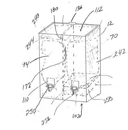
Figure 3 is a perspective view showing the
container blank assembled to form the container of the
present inventioni
Figure 4 is a top plan view of the container of
the present invention exposing the interior of the
container;
Figure 5 is a side view of one the individual
compartments of the container of the present
invention; and
Figure 6 is a cross sectional view taken along
the line 6-6 of Fig. 5 of the container with the bag
and dispensing means removed.
Referring to Figure 1, there is shown a
diagrammatic representation of a scored and creased
container blank from which the container of the
present invention is formed. The container blank 10
.
.,. , . ~. : .
. ,
. . .
: ' ', ' :. ' . .
2~ 7~
11
as illustrated in this Figure includes a first
rectangularly shaped main body panel 12. The first
main body panel 12 includes a free side 13, a side
margin 14 which is parallel to and spaced from the
free side 13, a top margin 16 and a bottom margin 18.
A first generally rectangularly shaped extension
panel 20 having a pair of free side edges 22 and 24, a
free bottom edge 26. The extension panel 20 is
foldably connected to the lower margin 18 of the first
main body panel 12. The main body panel 12 also
includes a generally rectangularly-shaped second
extension panel 28 which is foldably connected to the
upper margin 16 of the main body panel 12. The second
extension panel 28 includes a pair of spaced apart
parallel free side edges 30 and 32 and an upper margin
34. Foldably connected to the upper margin 34 of the
second extension panel 28 is a third extension panel
36 which is of a generally rectangular shape. The
third extension panel 36 includes a pair of spaced
apart parallel side margins 38 and 40 and a top margin
42. A pair of side extensions 44 and 46 are foldably
connected to the parallel side margins 38 and 40 of
the third extension panel 36. The side extensions 44
and 46 each have one free side edge 48, 50 and free
upper edges 52, 54 and lower edges 56, 58. There is
also provided a generally vertically oriented,
centrally located slot 60 extending from the upper
margin 42 of the third extension panel 36 to the upper
margin 16 of the maln body panel 12. There is
provided a fourth extension panel 62 which is foldably
connected to the upper margin 42 of the third
extension panel 36. The fourth extension panel 62 is
also generally rectangularly shaped and includes a
pair of spaced apart parallel free side edges 64 and
66 and a free top edge 68.
The container blank further includes a generally
- , : . ~ .: ~ . :
- :- . ',' ~ , ' , ,~ ' . '; ': '
' . : ,~ ~ . ,. ,., ": ~ ,'
,: , . . . . .
- :. ' ~' , ~ . ..
1 7 ~
rectangularly shaped first side panel 70 which is
foldably connected at one side with the side margin 1~
of the first main body panel 12. The fi.rst side panel
70 includes a side margin 72 which is spaced from and
parallel to the side margin 14 of the first main body
panel 12. Additionally, the first side panel 70
includes an upper margin 74 and a lower margin 76.
The first side panel 70 also includes kwo extension
panels, lower extension panel 78 and upper extension
panel 80. Lower extension panel 78 is foldably
connected to the lower margin 76 of the first side
panel 70 and has a pair of parallel free side edges
82, 84 and a free bottom edge 86. The upper extension
panel 80 is foldably connected to the upper margin 74
of the first side panel 70. The upper extension panel
80 has a generally trapezoidally shaped outline and
includes a pair of free side edges 88 and 90 and a
free top edge 92.
The container blank further includes a second
main body panel 94 which is foldably connected to the
side margin 72 of the first side panel 70 and includes
a parallel side margin 96. The second main body panel
94 also includes an upper margin 98 and a lower margin
100. A lower generally rectangularly shaped extension
panel 102 i5 foldably connected to the lower margin
lO0 of the second main body panel 94; the extension
panel 102 includes a pair of spaced apart parallel ,
free side edges 104, 106 and a free bottom edge 108.
The second main body panel 94 additionally includes a
pair of spaced apart perforated sections 110 proximate
the lower margin 100 but spaced therefrom. A further
extension panel 112 is foldably connected to the upper
margin 98 of the second main body panel 94. Extension
panel 112 has spaced apart parallel side margins 114,
116 and a top margin 118. Additionally extending
members 120, 122 extend Erom each of the side margins
:
-
., :
,,
2 ~ 7 ~
13
114. 116 and are of a generally trapezoidal shape eachhaving a free edge 12~, 126 associated therewith.
Extending from the top margin 118 i5 a further
generally rectangularly shaped extension member 128;
the extension member 128 has a pair of parallel spaced
apart free side edges 130, 132 and a free top edge
134. Extending from the top margin 118 is a cut out
tab member 136.
Additionally, the container blank 10 also incldes
a second side panel 138 of generally rectangular
shape, which is foldably connected to the side margin
96 of the second main body panel 94. The second side
panel 138 includes a side margin 140, an upper margin
142 and a lower margin 144. A first extension panel
146 is provided and is foldably connected to the lower
margin 144 of the second side panel 138. The first
extension panel 146 is generally rectangular in shape
and includes a pair of parallel spaced part free side
edges 148 and 150 and a free lower edge 152. A second
extension panel 154 of a generally -trapezoidal shape
is foldably connected to the upper margin 142 of the
second side panel 138 and includes a pair of free side
edges 156, 158 and a free top edge 160.
Foldably connected along the side margin 140 of
the second side panel 138 is a reinforcing and
partitioning extension 162. The reinforcing and
partitioning extension 162 comprises: a first
reinforcing panel 164 having upper and lower free
edges 166, 168 and a side margin 170; a partitioning
panel 172 having a free lower edge 174, an upper
margin 176 and a side margin 178 and further includes
an extension panel 180 fo]dably connected to the upper ~.
margin 176 and having a pair of spaced apart free side
edges 182, 184 and a free upper edge 186; and a second
rectangular reinforcing panel 188 foldably connected
:.
2 ~ 7 ~
1~
along side margin 178 to panel 172 and having a free
upper edge lso, a free lower edge 192 and a free side
edge 194.
According to a particularl~ preferred aspect, the
first and second side panels 70 and 138 have a width
approximately 1/2 to 3/4 the width of the first and
second main body panels 12 and 94, with a particularly
preferred width being 1/2 the width of the first ancl
second main body panels 12 and 94.
It is particularly preferred that reinforcing
panel 164 and partitioning panel 172 are the same
width as the first and second side panels 70 and 138.
Another preferred feature is that reinforcing
panel 188 has a width approximately 1/7 to to 1/4 the
width of partitioning panel 172.
Referring now to Figure 2, there is shown a
typical riser blank 200 to be used in association with
the container blank 10. The riser blank 200 comprises
a preferably square main panel 202 having a pair of
parallel side margins 204, 206, an upper margin 208
and a lower margin 210. Extending from the side
margins 204 and 206 are extension panels 212 and 214
which are foldably connected to the main panel 202.
The extension panels 212 and 214 have free end edges
213 and 215, respectively. AdditionaIly, there are
provided extension panels 216 and 218 which are
generally rectangular and are foldably connected to
the upper margin 208 and the lower margin 210,
respectively, of the main panel 202. The extension
panels 212 and 214 preferably include sloped free side
edges 224, 226 and 220, 222, respectively. The
extension panel 218 includes a free end 219 and free
side edges 221 and 223 and in a similar fashion, the
.
2 ~ 7 ~
extension panel 216 has a free end 205 and ~ree side
edges 211 and 213. Preferably the free end 219 of
the extension panel 218 includes a hemispherical
groove 228 centrally located thereon.
The riser blank 200 is formed into a riser member
258 (shown ln Figure 5) by folding the extension
panels 212, 214, 216 and 218 along the side margins
206, 204, 208 and 210 of the main panel 202,
respectively.
Having just generally described the container
blank lo an~ the riser blank 202 of the present
invention, the method of assembly of the container of
the present invention will now be described having
regard to Figures 1, 3, 4, 5 and 6.
In forming the container, with reference to
Figure 1, first main body panel 12 is folded along
side margin 14 in order that the first main body panel
12 is perpendicular to first side panel 70. In a
similar manner, first side panel 70 is folded along
side margin 72 and thus first side panel 70 is
perpendicular to second main body panel 94. At this
stage, second main body panel 94 and first main body
panel 12 are in a parallel relationship with first
side panel 70 spacing the first main body panel 12 and
the second main body panel 94. Second side panel 138
is folded along side margin 96 so that it is
perpendicular to second main body panel 94. The
reinforcing and partitioning extension 162 associated
with second side panel 138 is then assembled.
Reinforcing panel 164 is then folded along side margin
140 such that reinforcing panel 164 is disposed in
facing relation and contacts first main body panel 12.
Next, reinforciny panel 188 is folded along side
margin 178 in such a manner that it is disposed in
'
.: :
. :: ... .. .
'
.
,~ ,. ,;
2 ~ 7 ~
16
facing relatlon and contacts second maln body panel
94. As a result of foldlng relnforclng panels 188 and
164, partltlon panel 172 perpendlcularly orlented wlth
respect to flrst maln panel ~2 and second maln panel
94 within the compartment defined by the above
mentioned folding arrangement.
The formation is secured toyether by way of
suitable adhesives, such as by gluing so that
reinforcing panel 164 is adhered to first main body
panel 12 and reinforcing panel 188 is adhered to
second main body panel 94.
Having thus partially assembled the container,
extension 180 of partitlon panel 172 is then folded
downwardly toward the interior of the partially
assembled container along upper fold line 176 such
that it is in facing relation and contacts partition
panel 172. Extension panel 28 of the first maln body
panel 12 is folded downwardly and interiorly along
upper margin 16 such that extenslon panel 28 ls ln
facing relatlon and contacts first main body panel 12.
Extensions 44 and 50 of extension panel 36 are folded
upwardly along slde margins 38 and 40. Similarly,
extension panel 62 is folded along upper edge margin
42 upwardly to be in contact with interior upper
portion of second main body panel 94 thus forming a
accessory tray 240 at the top of the container (see
Figures 3 and 5). The accessory/storage tray 240 is
retained in position by folding upper extension panels
80 and 154 of side panels 70 and 138, respectively,
downwardly and interiorly so that they are in facing
and contacting relationship with their respective side
panels 70 and 138; and additionally the
accessory/storage tray 240 is frictionally engaged
with folded extension 180 of the partition panel 172
being inserted through the slot 60, thereby providing
., ,, - - ~
~ ' , ,
~ , : .
2~15~ 7~
a compartmented storaye area.
To form the bottom of the contalner, lower
extension panels 78 and ~46 of side panels 70 and 138,
respectively, are folded along lower margins 76 and
144 inwardly so that extension panels 78 and 146 are
perpendicularly disposed with side panels 70 and 138
respectively. Following this, extension panel 20 of
first main body panel 12 is folded in a similar
fashion along lower fo]d line 18 and finally,
extension panel 102 of second main body panel 94 is
folded along lower margin loO so that it is in
contacting and facing relationship with extension
panel 20 at which point it may be adhered thereto by
any suitable means thus providing the bottom of the
container.
In this manner of construction, the partition
panel 172 forms a pair of compartments 242 and 244
(shown in Figures 3 and 6) within the interior of the
container thus assembled.
Having thus assembled the riser blank 202 into a
riser member 258 and the container 10, the riser
member 258 is placed within the interior of the
individual compartments (see for example compartment
242 in Figure 3) at the bottom thereof in such a
manner that the hemispherical groove 228 of extension
panel 218 of the riser member 258 is so that it
registers with the perforated sections 110 of the
second main body panel 94.
Referring now to Figure 4 which shows a top plan
view of the container as above assembled, having bulk
dispensing plastic bags 246 and 248 disposed within
the individual compartments 242 and 244 of the
container. The bulk dispensing bags 246 and 248 may
.
~ ., ~ : ; ' .' :
2~ 5~ 7~
18
contain separate bulk source flowable liquid hair
products and preferably the bays are composed of the
known components used in the manufacture o~ these,
such as thermoplastic material haviny an aluminum
lamination. The bags may also have conventional
manually actuatable dispensing valves 250, 252. The
perforated outlines 110 of the second main body panel
94 are "punched out" thus providing apertures therein
from which the dispensing valves 250 and 252 of the
bags 246 and 248 may project. The individual bags
246 and 248 are inserted into the individual
compartments 242, 244 of the container in such that
they rest on the riser member 258 and so that the
dispensing valves 250 and 252 protrude outwardly from
the above described apertures and are further
supported by the hemispherical groove 228 of the riser
member 258. As the riser member 258 rests in an
angled position within the compartment 242, the fluid
within the bag 248 would be constantly urged towards
the dispensing means 252 thereby permitting ready flow
of fluid even when the fluid level in the bag is
extremely low. The bag 246 would be set up within
compartment 242 in a similar manner as that described
above utilizing a similar riser member.
Once the bags 2~6 and 248 have been inserted into
the individual compartments 242 and 244 as described
above and the valves 250 and 252 are in place as noted
above, the extension panel 112 of the second main body
member 94 and its extensions 120, 122 and 128 are
folded inwardly along their margins 98, 114, 116 and
118, respectively and the extension panel 112 is then
pressed downwardly so that extensions 120, 122 and 128
slide into slots which have been previously formed by
the construction of the contai.ner.
As those skilled in the art would realize the
19
above referred to preferred illustrated dimensions,
details and componen-ts can be subjected to substantial
variation, modification, change, alteration, and
substitution without affecting or modifying the
function of the illustrated embodiments. Although
embodiments of the invention have been described
above, it is not limited thereto, and it will be
apparent to persons skilled in the art that numerous
modifications and variations form part of the present
invention insofar as they do not depart from the
spirit, nature and scope of the claimed and described
`invention.
- . ; , ,
.
'. '` . . `; ' '