Note: Descriptions are shown in the official language in which they were submitted.
2015334
1 ONE STEP PULL TAB CAP-LINING MACHINE
3 Background
4 Currently, many applications exist for providing tamper
evident safety seals on the tops of bottles containing a variety
6 of different products. Aluminum foil seals commonly are used for
7 sealing such bottles containing petroleum products, food
8 products, medicines, etc.. The aluminum foil seal is adhered to
9 the upper end of the bottle neck, and the seal usually is formed
from a liner comprlsing a laminate of aluminum bonded to a
11 suitable polymer which may be induction heat sealed to the top of
12 the bottle. Once the seal is in place, the seal insures that no
13 foreign materials subsequently enter the bottle after it has been
14 sealed and prior to its ultimate use. A second important purpose
is that if tampering is attempted, the seal must be altered or
16 destroyed because access to the interior of the bottle cannot be
17 accomplished without doing this.
18 While such tamper evident seals serve the intended purpose
19 of protectlng the bottle contents from unauthorized access, they
are difficult to remove. Generally, it is necessary to use a
21 knife or other sharp object to break the seal and tear it away
22 from the edge of the bottle neck. This usually leaves a ragged
23 opening around the edge of the bottle and sometimes results in a
24 spilling of some of the contents of the bottle durins the efforts
to remove the seal.
26 Patent #4,754,890 to Ullman discloses a seal and a machine
., ~
2015334
1 for making it which forms a tab or protuberance on the edge of
2 the seal. This tab projects upwardly from the seal when the cap
3 is removed from the top of the bottle. The tab then may be
4 grasped by the user to peel the seal off the top of the bottle.
The tab and seal formed by the device of the Ullman Patent are
6 formed in a single punch operation, but it is necessary first to
7 fold the foil material under itself along both-edges prior to the
8 punch operation. The punch then extends past this folded portion
9 to form a folded under tab at the time the cap insert is made.
Thus, it is necessary to provide separate apparatus to fold under
11 the edges of the foil strip from which the seals are formed. A
12 problem also exists in maintaining the precise alignment
13 necessary to insure that the tab is not cut off ana that it is of
4 sufficient strength to prevent it from being torn away when the
seal is to be removed fro~ the bottle. In addition, forming the
16 tab in this manner causes a flat edge to be also formed on the
17 seal i~self, which limits the size of the tab which can be
18 formec. I is difficult to maintain the necessary alignment to
19 overcome these problems.
Two other patents which disclose the need for providing a
21 pull ab on a membrane cover over the opening in a metal can, are
22 the Patents to Hardt ~4,328,905 and Wright et al. ~4,544,08C.
23 Neither o~ these patenls, however, disclose the manner in which
24 the tabs are formec.
Ano~her techni~ue which has been employe~ is to utilize
26 prog essive dies to first form a tab from a sheet of liner
2(~15334
. _
1 material passing through the liner insert machine. The tab is
punched at a first position with a tab punch; and as the liner
advances, the tab is folded under the liner material. This
4 punched-folded tab then advances to the liner punch station where
it is punched out as a part of the liner insert. Since the tab
6 is folded under the insert, which then is inserted into 2 cap
7 with the tab located between the cap and the line , it
8 subsequently can be utilized to remove the insert from a
9 container on which the cap ultimately is attached. For a
progressive die system of this type to work properly, the tab
11 must be folded and creased without any defects, and then held
12 folded until it reaches the liner insert punch station. Once the
13 tab is located at the liner insert punch station, alignment is
4 critical. If the tab fold is not far enough into the punch
station, the tab will be cut off. Also, if the tab is too far
16 into the punch station, slits between the tab and the liner
17 insert will result. These slits ultimately will cause the tab to
18 tea- away from the main liner insert when it is pulled to remove
19 the insert from the container on which the insert ultimate'y is
attached. This then leaves the main portion of the insert
21 unremoved, with a rip or opening through i'. Consequen~ly, if
22 significant precision is not maintained in such a progressive die
23 system, faulty product results.
24 Il is desirable to provide a cap-linins machine which
2~ produces pull tab liner insert disks whic~ are no' subject to the
26 disadvantages of the prior art. Ideally, it is desirable to
2015334
1 provide a one-step punch and die and insert operation to produce
2 a tab liner insert seated in a cap, all as part of a single
3 machine operation.
Summary of the Invention
6 It is an object of this invention to provide an improved
7 one-step tab liner insert for~ing machine.
8 It is another object of this invention to provide an
9 improvement in the provision of a ta~per evident safety seal
having an at.ached tab to faciliate subseouent removal of the
11 seal from the container on which il is placed.
12 It is an additional object of this invention to provide an
13 improvea cap lining machine.
14 It is a further object of this invention to provide an
improveZ machine for producina a tamper evident insert seal with
16 a grasping tab and for installing such seals in a cap.
17 In accordance with a preferred e~.bodiment of the invention,
18 a -aF-lininc machine proauces tab liners and places such liners
19 in a caF in a single step operation. To do this, the machine
incluaes 2 stamping die with 2 first portion shapec to correspond
21 with 'he internal size of a cap to be lined with a liner. A
22 secona S~2l ler aZjacent portion extenas from the first portion
23 anc is shapec to form ar. extending pull tab, so tha. the two
24 portions of the die together form 2 single opening in the die. A
punch has first and secona por-ions which mate, respec.ively,
26 wilh the firs ana seconc por.ions of the die. The punch is
2015334
1 moveable between retracted and punching positions to punch cap
inserts with an extending tab on them from liner material located
3 at the punching position. The structure of the punch and the die
4 is such that, during the punching operation, the tab first is cut
and folded under the liner insert portion as the punch moves
6 through its punching position. Once the liner with the attached
7 tab has been punched, it is seated into a cap located beneath the
8 punch as the final portion of the one-step punching and seating
9 operation.
11 Brief Description of the Drawing
12 Figure lA is a partially cut-away side view of a preferred
13 embodiment of the invention in a first stage of operation;
14 Figures lB throuqh lD illustrate a portion of the embodiment
of Figure l in three successive stages of operation;
16 Figure 2 illustrates a pull tab insert of the type formed by
17 the apparatus of Figure l;
18 Figure 3 is a view taken along the line 3-3 of Figure l; and
19 Figure 4 is a view taken along the line 4-4 of Figure l
showing details of a por~ion of the apparatus of the embodiment
21 of Fiaure l.
22
23 Detailed Description
24 Reference now should be made to the drawing, in which the
same reference numbers are used throughout the different figures
26 to designate the same components. In addi~ion, reference also
-- 2015334
should be made to the Patent ~4,728,239 to ~ieran and Rickenbach,
2 assigned to the same assignee as the present application. This
3 patent illustrates a cap lining ~r,achine of a type which 11~2y be
4 modified to incorporate the present invention and describes in
S greater detail the overall operation of a system for forTr.ing cap
6 inserts and placing theJr; in caps in a high speed automatic
7 operation.
8 Figures lA through lI~ of the present application are similar
9 in ~r,any respects to ~igures iA through 5C of Patent $~4,728,239,
10 and those colrponents whic~. are su~stantially the same as the
11 coJrponents of Patent ~4,728,239 have been given the same
12 reference numbers in Figures lA through lD as they are given in
~3 ~igures 5A through 5C of the '23g Patent. Reference should be
14 ~r,ade to the specification of Patent ~4,728,239 for a more
15 com~lete aescription of the overall operation of the basic cap
16 lining Tr.achine.
17
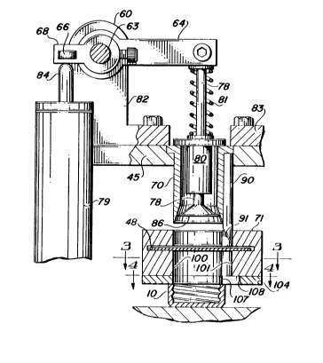
18 ~eference now shoulà be made to ~igure lA. In the operation
t9 of the ~r,achine aescribea in Patent ~4,728,2~9, a cap l0, into
20 which an insert is to be placea, first is centered ~irectly
21 benea'h an opening l0Q in 2 die 71, which is locatec beneath c
22 punch block 45. In the -e~racted position shown in Figure lA,
23 the punch block 45 ano 2 punclh coIrp-isinS a first portion 70 and
24 c seconc ta~ cu.~in~ portion gn, is located in the retrac.eo
25 position. Once the cap l0 is locatea as shown in Figure lA, the
26 punch ~lock 45 is lowerec 2S aesc.ibeo in the '2~9 Patent, 'o
.~
2~1S334
1 punch out a liner insert. The se~uence of operation for
accomplishing.this is shown in Figures lA, lB, lC, and lD.
The punch portions 70 and 90 move downwardly together from
4 the position shown in ~igure lA first to ~he position shown in
Figure 1~. As illustrated in Figure lB, the tab cutting portion
6 go of the punch first enters into a tab opening 101 in the die 71
7 to cut a tab 75 from a web 48 of the liner ~,aterial. The side of
8 the punch portion 90 which faces the main cap insert opening 100
9 in the die 71 is tapered at a relatively sharp angle 91 to cause
0 the tab 75 which is cut by the punch 90 to curl toward the left,
11 as viewed in Figure lB, as the punch block 45 moves downwardly to
12 effect the punching operation.
13 The punch block 45 continues its downward movement to the
14 final punching position shown in ~igure lC. In this position, it
can be seen that the punch portion 7.0, cooperating with the
16 circular aperature 100 in the die 71, causes a circular cap liner
17 insert 74 to be cut fro~l the web 48. The punch carries the
18 liner insert 74 ana the curled under tab 75 to a position where
19 it engages the upper eage of a circular opening in a folding
member 104 attached to the bottom of the die 71. This folding
21 member 104 is not present in the device of Patent ~4,728,239, and
22 it hac a c oss section as illustrated in ~igure 4.
23 It can be seen that there is a circular opening in the
24 member 104 which conforms with and is aligned with the opening
100 in the die 71. In addition, there is a second opening 108
26 which per~,its the cutting tip of the punch portion 90 to pass
20~5334
through it as the punch continues the downward movement shown in
2Figure lC. The two openings in the melr.ber 104 are joined by a
3folding rib 107.
4The folded edge of the liner insert, where the tab 7~ joins
5the main body portion 74 of the insert, engages the thin folding
6rib 107 to crease the tab 75 firlrlly underneath the main body
7portion 74 of the insert. This is illustrated in Figure lC which
8shows the folded edge of the tab 75 engaging the top of the
9folding rib 107. Also, it is readily apparent from an
10examination of Figure lC that once the punch block 45 has reached
11this lowermost position, the cutting end of the punch portion 90
12is inserted through the opening lC8 in the folding mem.ber 104.
13In the position shown in ~igure lC, the liner insert 74 with
14its connected tab 75 is located adjacent the lower edge of the
15die block 71 and above the open top of the cap 10. his location
16also is significantly above the bottom of the cap 10 into which
17the insert 74 is to be pressed.
18As aescribed in Patent #4,728,2~9, placemen of the liner
19inserts 74 in the cap 10 is accorGpllshed by means of a
20reciprocating tamper 86 attachec to a shaft 78. The tamper shaft
2178, which terlr.inates in the tamper 86, is concentrically mounted
22in a cartridge 80 located within the hollow ?unch 70. A flange
23on the top of the cartridge 80 extends outwardly over the upper
24ena of the punch 70 for su?port; and the tamper shaft 78 is
25sprins '~iased to an upwara or retracted position by a spring 81,
26 ~ as bes' il lustratea in Figure 1~. The compression spring 81
21~1~;334
extends between the top of the cartridge 80 and a circular flange
attached to the upper end of the tamper shaft 78. The flange on
3 the upper end of the tamper 78 then engages the end of a rocker
4 arm 64.
The rocker arm 64 is attached to a shaft 63 which is m,ounted
6 for a rotation between a pair of rocker arlr support blocks (not
7 shown here, but describe2 in Patent ~4,728,239). One end of the
8 shaft 63 extends through a bearing block 60 where it is attached
9 to an operating lever arm 68 extending to the lef~ of the shaft
64, as viewed in Figure lA. The outer end of the lever 68 has a
11 removable projection 66 mounted on it. The projec.ion 66 extends
t2 to one side (out of the surface of the paper, as illustrated in
13 Figure lA) over a plunger 84 mounted in an air cyl inder 79
14 attached to a common base plate (not shown) for the apparatus.
1~ When the punch block 45 is in its retracted position, as
16 shown in Figure lA, the projection 66 is locatec in a position
17 just touchin~ or spaced slightly above the end of the plunger 84.
18 As a punch block 45 is drawn downwardly to commence and complete
19 the punching cycle, the projection 66 engages ~he end of the
20 plunger 84 causing the rocker arm,, comprising the lever arms 68
21 and 64, to rotate in a clockwise direction abou. the shaf. 63.
22 The ratio of the length of the lever arm 68 to that of the arm 6~'
23 is approxiJr.ately 1:2. This _ause.s the righthand end of the lever
24 64 to move the upper end of the tamper rod 78 downwardly against
25 the bias of the sprins 81 at a rate and to a 2istance twice that
26 of the aownwara movement of the punch 70, 90. As the punch
201S334
1 portion 70 completes the severance of the insert liner 74 fro~
2 the web 48, the enlarged end 86 of the tamper 78 engages the top
3 side of the liner insert 74, as shown most clearly in Figure lC.
4 Continuation of the downward movement of the punch 70 and tamper
78 against the bias of the s?ring 81, however, causes the tamper
6 78 to move the portion 86 past the end of the punch 70, as
7 indicated in Figure lD.
8 Completion of the movement of the tamper head 86 through the
9 operation of the rod 78, to firmly seat the insert 74 (with the
tab 75 folded under it) in the cap lO, is effected by operation
11 of the air cylinder 79 to ~ush the plunger 84 upwardly upon
12 termination of the downward movement of the punch block 45. The
13 air cylinder 79 and plunger 84 also act as a gas spring to effect
14 cushioned sea.ing of the liner 74 in the cap lO. This "gas
1~ sprins" also absorbs the consequences of an upside down cap or
16 jam up without damage to the m,achine.
17 The punch block 45 then is raised from .he position shown in
18 Figure lD back to the retracted position shown in Figure lA by
19 any suitable manner, such as described in Patent ~4,728,239. The
machine then is ready to commence another cvcle of operation,
21 followino the movement of a new cap lO into position beneath the
22 a~paratus as shown in Figure l~.
23 ~'hen the ca~ lO, with i~s liner insert 7~ in place, as shown
24 in Figure l~, is movea out Oc the punch mechanism, it is ready to
2~ be installed on the upper end of â container, such as 2 glass or
26 plastic bo'tle neck. I is readilv apparent from the foregoing
lG
-- 20~334
1 description that the sealing liner insert 74 initially is
independent of the bottle and is ready to be shipped to a
3 bottler, where it subsequently is assembled mechanically to the
4 bottle. The sealing liner insert is captured in the bottle cap
lO, so that it can be handled in any suitable manner. Typically,
6 the sealing liner, as described previously, is a sandwich of
7 aluminu~ foil bonded to a mylar backing. The mylar backing side
8 of this sandwich faces the open end of the cap 10.
9 After the bottler has filled the bottle or other container,
0 the cap lO is mechanically ~laced on the bottle and securely
11 tightened in a conventional manner. The combined closure
12 consisting of the cap 10 and sealing liner insert 74, with its
13 attached tab 75, then is subjected to induc~ive heat, such as
14 produced in a high frequency tunnel, to cause the mylar or other
polymer to fuse to the upper end of the bottle neck to close the
16 mouth of the bottle. This provides the desired tampe. evident
17 safety seal. ~hen the cap 10 subsequentlv is removed by a
18 customer, the aluminum foil side of the inser_ 74 is visible, ana
19 the laminated tamper evident seal is adhered to the bott~e. The
tab 75 then is visible to assist in subsequent removal of the
21 Seal 7~.
22 Since the seal 74 and tab 75 are simul.aneously formed in
23 the manner describe~, there is no possibilitv of cutting off the
24 tab 75 or form.ina slits or lines of weakenin~ between the tab 75
and the seal 74. The opera_ion si~ply and effec.ively for~s the
26 tab simultaneously with the liner inserl 7~, and in the sa~e
201S334
1 sequence of operation of the punch mechanism described in Patent
2 $4,728,239, completes the folding under of the tab 75 to a
3 location which effectively presents it for non-interfering
4 insertion into a cap 10.
The modifications to the punch and die mechanism of Patent
6 #4,728,239 .o accomplish this purpose actually reauire very few
7 additional parts. None of the basic operating mechanism of the
8 punch and die mechanism of the '239 Patent needs to be changed.
9 The die 71 is cut to include the tab opening 101; and the punch
is modified to include the tab punching portion 90, with its
11 inwardly sloped surface 91, as described previously. Finally,
12 the only other addition is the folding ring 104, with the rib
13 107.
14 Various changes and modifications will occur to those
skillec in the art without departing from the true scope of this
16 invention as defined in the appended claims. The foregoing
17 desc-iplion of the apparatus, particularly as it is described in
18 conjunctior. with a specific punch and die operating mechanism, is
19 to be considered illustrative and not as limitins. The operation
Of the punch anc die may be effected by various standard cam or
21 gear operatec mechanisms, as well as the one aescribed in
22 conjunction with the preferred embodiment, without departing from
23 the scope o, the invention.
24
2~ -
26