Note: Descriptions are shown in the official language in which they were submitted.
2 ~ 2 6
SOCKET ASSEMBLY ~-
.. . . ...
Background of_the_Invention
The present invention relates to a method of assembling
a new and improved socket assembly which receives a plug to
enable fluid to be conducted between the socket assembly
and plug.
A known socket assembly which is used in a quick
disconnect coupling is disclosed in U.S. Patent No.
2,805,089 issued September 3, 1957 and entitled "Pipe ... :.
Coupling With Wedged Spring Ring Detent Means". This ;~
socket assembly includes two castings or socket parts which ~;
are threadably connected together. An annular rubber seal
ring or gasket seals a joint between the socket parts. In
addition, prior~to insertion of a plug, a valve member in
the socket assembly engages the seal ring to block fluid --
~low through the socket assembly.
Internal and external threads must be formed on the
parts of this known socket assembly by separate ma~hining
;, ~ ,`'
~ ! .,,
' .'' "'.
2 0 1 ~ ~ 2 ~
.
': :
operations in order to enable the soc~et parts to be
interconnected. Of course, the machining operations
required to form the internal and external threads on the
socket parts contributes to the cost of making the socket
assembly. In addition, the joint between the socket parts
can be loosened so that it is no longer fluid tight by
rotating one of the socket parts relative to the other
socket part.
Summary of the Invention
.
An improved socket assembly receives a plug to enable
~luid to be conducted between the socket assembly and the
plug. The socket assembly includes a socket body having
first and second socket parts which a~ interconnected by a
retainer ring disposed in grooves in the socket parts. A
resilient seal ring is compressed between surfaces on the
socket parts to press the socket parts against the retainer
ring.
When the first and second socket parts are to be
interconnected, the retainer ring is telescopically
positioned on an end portion of the first socket part at a
location offset from an outwardly opening groove in the
first socket part. The retainer ring is engaged with the ~
outwardly opening groove in the first socket part and an ~-
inwardly opening groove in the second socket part by
pressing against the retainer ring with the second socket
2 ~
part to move the retainer riny toward the groove in the
firs~ socket part and resiliently expand the retainer
ring. As the retainer riny is moved toward the groove in
the first socket part, a seal ring is compressed between
the two socket parts. After the socket parts have been
interconnected, a plug can be inserted into a socket
chamber formed by at least one of the socket parts. A
locking assembly is disposed on the one socket part to
engage the plug and hold it in the socket chamber.
Accordingly, it is an object oE this invention to
provide a new and improved method of making a socket
assembly and wherein a retainer ring is moved into
engagement with grooves in a pair of socket parts by
pressing against the retainer ring w;lth one socket part to
resiliently expand the retainer ring and move the retainer
ring toward the groove in the other socket part.
Another object of this invention is to provide a new
and improved socket assembly for receiving a plug to enable
rluid to be conducted between the socket assembly and the ~ ~-
plug and wherein a retainer ring is disposed in grooves in
first and second socket parts to connect the first socket
part with the second socket part.
Brief Descri~tion of the Drawin~s
The foregoing and other objects and features of the
present invention will become more apparent upon a
- 2 ~ 2 ~
--4--
consideration of the following description taken in
connection with the accompanying drawings, wherein:
Fig. 1 is a partially broken away sectional view of a
socket assembly constructed in accordance with the present
invention;
Fig. 2 is a sectional view illustrating the construction - '
of a plug which is received in the socket assembly of Fig.
1 to enable fluid to be conducted between the plug and
socket assembly;
Fig. 3 is an enlarged fragmentary view of a portion of
Fig. 1 illustrating the manner in which a retainer ring
engages grooves in a pair of socket parts to interconnect
the socket parts and the manner in which a resilient seal
ring is compressed between the socket parts;
Fig. 4 is an illustration of the socket parts of Fig. 3
before they are interconnected, the retainer ring being
shown telescopically positioned on an end portion of a
first one of the socket parts at a location axially offset
rom an outwardly opening groove in the first socket part; ~ '
Fig. 5 is an enlarged illustration, similar to Fig. 4, ~`'
of the manner in which the second socket part is pressed -~
against the retainer ring to move the retainer ring!axially
toward the groove in the first socket part and resiliently
expand the retainer ring; and
Fig. 6 is an illustration of ~,he relationship between
the socket parts of Figs. 3-5 immediately before the
~ "~
2~82~
retainer ring engages the outwardly opening groove in the
first socket part.
Description of One Specific
Preferred Emb _iment of the_Invention
Socket Assembly_- General ~escription
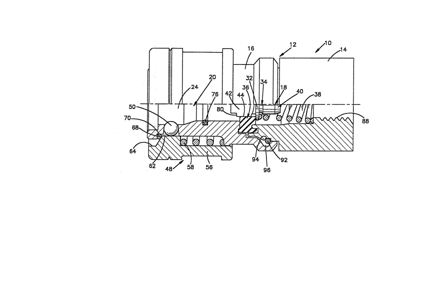
An improved socket assembly 10 constructed in
accordance with the present invention is illustrated in
Fig. 1. The socket assembly 10 includes a socket body 12
having a cylindrical first or inner socket body part 14 and
a cylindrical second or outer socket body part 16~ A valve
assembly 18 is disposed in a socket chamber 20. The valve :`
assembly 18 blocks fluid flow between an inner portion 22
and an outer portion 24 of the socket chamber 20 when a
plug 26 (Fig. 2) is separate from the socket assembly 10.
The valve assembly 18 has the same construction as is `~
disclosed in U.S. Patent No. 2,805,089. ~:
When the valve assembly 18 is in the closed condition ~.
of Fig. 1, an annular flange 32 on a valve member 34 is
pressed against an annular seal ring 36 by a valve spring
38. The valve spring 38 engages a spring mounting section
40 of the valve member 34 to position the coil spring
relative to the valve member. A flat guide section 42 ~:~
extends outwardly from the flange 3~ through a circular
opening 44 in the seal ring 36.
A locking assembly 48 is provided on the second or
outer socket part 16 to retain the plug 26 (Fig. 2) in the
','~ ''"'
2~ 8~ ~
--6--
socket assembly 10 (Fig. 1). The locking assembly 48
includes a plurality, in the illustrated embodiment of the
invention three, spherical locking or detent balls 50. The
stainless steel locking balls 50 project into the outer
portion 24 of the socket chamber 20 to engage a circular
locking groove 52 (Fig. 2) formed in the brass plug 26.
A cylindrical metal locking sleeve 56 (Fig. 1) is
movable between the engaged position shown in Fig. 1 and a
retracted or disengaged position. When the cylindrical
locking sleeve 56 is in the engaged position shown in Fig.
1, a cylindrical inner side surface 62 on the locking
sleeve presses against the locking balls 50 to hold them in
the engaged position shown in Fig. 1. ~hen the locking
sleeve 56 is manually moved toward the right, as viewed in
Fig. 1, against the influence of the biasing spring 58, a
circular recess 64 in the outer end portion of the locking
sleeve 56 moves into alignment with the locking balls 50.
The recess 64 enables the balls 50 to move radially
outwardly relative to the cylindrical outer or second ;
socket part 16. A circular snap ring 68 is disposed in a
groove 70 at the outer end of the outer socket part 16 to
limit axially outward movement of the locking sleeve 56
under the influence of biasing spring 58.
When the plug Z6 (Fig. 2) is to be inserted into the
socket assembly 10, the locking s~eeve 56 (Fig. 1) is
pulled inwardly against the influence of the biasing spring
:
J
--7--
58 to move the groove 64 into radial alignment with the
locking balls 50. Tllis enables the locking balls 50 to be
moved radially outwardly to a disengaged condition by the
plug 26 as it is inserted into the socket chamber 20.
As the plug 26 is inserted into the socket chamber 20,
a cylindrical outer side sur~ace 74 (Fig. 2) on a leading
end portion of the plug 26 is engaged by an O-ring seal 76
(Fig. 1) in the outer socket body part 16. Immediately
thereafter, an annular leading end surface 78 on the plug
26 engages a shoulder 80 formed on the ~lat guide section
42 of the valve member 34. Continued movement oE the plug
26 into the socket chamber 20 moves the ~lange 32 on the
valve member 34 away from the seal ring 36 against the
influence of the valve spring 38. As this occurs, the
locking balls 50 are moved outward by an annular cam ring
or collar section 84 (Fig. 2) of the plug 26.
As the plug 26 moves still further into the socket
chamber 20, the cylindrical leading end portion 74 of the : :
plug is telescopically received in and seals against the
sides of the circular opening 44 in the seal ring 36 (Fig.
1). As this occurs, the locking balls 50 engage the
annular groove 52 in the plug 26. The cylindrical locking
sleeve 56 is then released and the balls 50 are cammed
inwardly into locking engagement with the retaining groove
52 in the plug 26 by the sleeve a~. it moves axially
outwardly under tbe influence of the spring 58. The
--8--
locking balls 50 then cooperate with the annula~ cam ring
or collar section 84 of the plug 26 to ~irmly hold the plug
in the socket chamber 20.
During movement of the plug 26 into the socket chamber
20, the valve member 34 is moved from the closed position
of Fig. 1 to a fully open position against the influence of
the biasing spring 38. This movement of the valve member
is guided by engagement o~ the flat guide section 42 of the
valve member with the cylindrical inner side surface 44 of
the seal ring 36.
When the valve member 34 is in the open position, fluid
can flow along opposite sides of the flat guide section 42,
through the seal ring 36 and around the flange 32 to enable
fluid to be conducted either from thé inner portion 22 of
the socket chamber 20 to the plug 26 or to be conducted
from the plug 26 to the inner portion 22 oE the socket
chamber. Although the plug 26 and socket assembly 10 can
each be connected to separate fluid conduits, internal
threads 88 on the inner or first socket part 14 may
advantageously be connectied with a valve which controls the
flow of gas from a tank or other source. In this specific ;
instance, the plug 26 is connected in fluid communication
with a concluit connected to an appliance in which the gas ~ -
is burned in a manner similar to that disclosed in U.S.
Patent No. 4,280,523, issued July, 28, 1981 and entitled
"Thermal Responsive Coupling".
2 ~
g
When the plug 26 is to be disconnected from the socket
assembly 10, the locking sleeve 56 is retracted against the
influence of the biasing spring 58. This enables the
collar or cam section 84 on ~the plug 26 to ca~ or force the
locking balls radially outwardly into the groove 64 in the ~-
sleeve 56 as the plug is withdrawn from the socket chamber
20. During movement of the plug ou~ of the socket chamber
20, the valve member 34 is moved back to the closed
position shown in Fiy. 1 by the valve spring 38. This
moves the flange 32 on the valve member 34 back into
sealing engagement with the seal ring 36 to block fluid
flow through the valve assembly 10.
Retainer Ring ~ ;
In accordance with one of the features of ~he present
invention, the inner and outer socket parts 1~ and 16 are
held in the telescopic relationship of Fig. 1 by a retainer
ring 92 in the manner illustrated in Fig. 3. The annular
stainless steel retainer ring 92 engages an annular
outwardly opening groove 94 ~Fig. 3) in the brass first or
inner socket part 14. In addition, the retainer ring 92
engages an annular inwardly opening groove 96 formed in the
brass second or outer socket part 16. The retainer ring 92
retains the first and second socket parts 14 and 16 against ;~
movement relative to each other by abutting engagement of
side surfaces of the grooves 94 and 96 with side surface
areas of the retainer ring 92.
. .
2 ~
; Thus, a radially extending axially outer cylindrical
side surface 102 of the outwardly ope~ing groove 94 engages
a surface area on the left side (as viewed in Fig. 3) of
the retainer ring 92. Similarly, a cylindrical side
surface 104 of the inwardly opening groove 96 on the outer ~ :
socket part 16 engages a right side of the retainer ring
92. Abutting engagement of the side surfaces 102 and 104 :~
of the grooves 94 and 96 with the retainer ring 92 prevents
the socket parts 14 and 16 from moving out of the engaged
relationship shown in Fig. 3
The elastomeric seal ring 36 is resiliently compressed
between the outer or left end portion (as viewed in Fig. 3)
o~ the fi~st or inner socket part 14 and the inner or right
end portion of the outer socket part 16. This enables the
seal ring 36 to apply a force against the socket parts
urging the sides 102 and 104 of the grooves 94 and 96
against the retainer ring ~2. The compressive load force ~;
applied to the socket parts 14 and 16 by the seal ring 36
prevents wobbling movement between the socket partsO
Interconnecting the Socket Parts
When the socket parts 14 and 16 are to be
interconnected to Eorm the socket body 12, the seal ring
3~, valve member 34 and valve spring 38 are positioned in
the second or outer socket body part 16, in the manner :-
shown in Fig. 4. The annular retainer ring 92 is
positioned on the leading or outer end portion 108 of the
first or inner socket part 14. Thus, the annular retainer
ring 92 is slid over a bulbous nose or outer end 110 on an
annular outer end portion 108 of the inner socket part 14.
As the annular retainer ring 92 is slid over the
circular bulbous nose portion 110, the ring expands
slightly. It should be understood that the retainer ring
92 is not continuous, but rather has a radially extending
gap or slit which is closed when the retainer ring in the
relaxed or normal condition. As the retainer ring 92 is
slid over the bulbous nose portion 110, the radially
extending slit in the retainer ring increases slightly in
size to accommodate resilient expansion of the retainer
ring. Once the retainer ring 92 has been moved over the
nose 110, the slit closes and the retainer ring assumes its
initial or undeflected condition. However, the retainer -~
ring is held against inadvertent falling off of the end
portion 108 of the inner socket part 14 by the bulbous nose
110. ' '
The outer end portion 108 of the inner socket part 14
and the inner end portion 116 (Fig. 4) of the outer socket
part 16 are then moved into a telescopic relationship with
each other. This can be accomplished by moving either one
of the two socket parts axially toward the other socket
part or by simultaneously moving ~oth socket parts
together. As the socket parts 14 and 16 are moved from the
- ` 2 ~
-12-
.
separated relationship illustrated in Fig. 4 into a
telescopic relationship (Fig. 5), an axially trailing side
surface 122 o~ the groove 96 is moved into abutting
engagement with an axially trailing side of the retainer
ring 92. As the telescopic relationship between the socket
parts 14 and 16 increases, the trailing side sur~ace 122 on
the outer socket part 16 pushes the retainer ring 92
axially inwardly toward the outwardly opening groove 94. -~
Thus, the retainer ring 92 is moved axially from the
initial position shown in Fig. 4 through the positions
shown in Figs~ 5 and 6 into the groove 94 (Fig. 3).
As the resilient stainless steel retainer ring 92 moves
I axially toward the groove 94 under the influence of force
applied against the retainer ring by the outer socket part
16, the retainer ring 92 slides along an outwardly ~laring
ramp or cam surface 124 on the inner socket part 14. The
I cam surface 124 is formed as a portion of a cone and is
il effective to resiliently expand the retainer ring 92, in a
radial direction, as the retainer ring moves axially toward
the groove 94. Thus, as the retainer ring 92 moves from
the position shown in Fig. 4 to the position shown in Fig.
5, the size of the radial slit in the retainer ring 92 and
the circumference of the retainer ring 92 increases and the
retainer ring is resiliently expanded radially outwardly.
~, As the telescopic relationship between the socket parts
14 and 16 i.ncreases, the annular outer end portion 108 of
"~,"~ ,"":~ ,"', - ~' '-,':'; ~ ,~; ,''~ ;'~'~;'',, ~'; '
2 ~ -3 g '~ ~
-13-
the inner socket part 1~ cooperates with an annular outer
side surface 128 of the seal ring 36 and a cylindrical inner
side surface 130 on the socket part 16 to guide telescopic
movement between the socket parts. Shortly after an annular
guide section 112 on the inner socket part 14 has entered ~:
the space between the cylindrical outer side surface 128 of
the seal ring 26 and the cylindrical inner side surface 130
of the outer socket part 16, an annular rim 134 on the
inner socket part 14 engages the seal ring 36 (Fig. 5). As .
the telescopic relationship between the socket parts 14 and .
16 continues.to increase, the rim 134 compresses the seal
ring 34 against an annular outwardly facing side surface .
136 on the outer socket part 16. As the seal ring 36 is
resiliently deformed by the circular rim 134 on the inner
socket part 14, the polymeric material of the seal ring 36
is compressed between the rim 134 and the circular side
surface 136 on the outer socket part 16.
As the telescopic relationship between the socket parts
14 and 16 continues to increase, the retainer ring 92 is
pushed axially along the flaring cam or ramp surface 124
toward the outwardly facing groove 94 in the inner socket
~ ~ I
part 1~. As the retainer ring 92 moves from the initial
position of Fig. 4 toward the groove 92, the outwardly
flaring cam or ramp surface 124 applies a radially ~:~
outwardly directed force against ,a radially inner side of ;:
the retainer ring 92. This force increases the diameter of ~:
' ~
2~3~2 1~
-14-
the retainer ring and expands the retainer ring (Figs~ S
and 6). :~
As the retainer ring 92 resiliently expands from the
initial condition of Fig. 4 t:hrough the condition shown in
Fig. 5 to the condition shown in FigO 6, the retainer ring ;-
slides radially outwardly along the annular trailing side
surface 12~ of the groove 96 toward an annular bottom :
surface 138 of the groove 96. Of course, as the retainer
ring 92 is sliding radially outwardly along the trailing
side surface 122 of the groove 96, the trailing side
surface of the groove is applying an axially inwardly
directed force against the retainer ring 92.
Immediately before the retainer ring 92 enters the ~ -
groove 94 (Fig. 6), the retainer ring is positioned on an
axially outer edge of the groove 94. At this time, the
retainer ring 92 has been radially expanded to a maximum
extent and is ready to snap into the groove 94 on the next -~
increment of movement of the retainer ring toward the
groove. As the telescopic relationship between the socket
parts 14 and 16 increases incrementally from the
relationship shown in Fig. 6, the center of the retainer
i ,~ , , : . . .
ring 92 moves axially inwardly of the axially outer side
surface 102 of the groove 94. As this occurs, the natural
resilience of the retainer ring 92 causes it to snap into ~ :
the groove 94 to the position show,n in Fig. 3.
As the retainer ring 92 contracts radially and enters
the groove 94, the retainer ring is cammed axially inwardly ;
' ~ ,'
-15~ 2 ~
:
so that an axially leading or right side (as viewed in
Figs. 3 and 6) of the retainer ring 92 moves into abutting
engagement with an axially leading side surface 104 of the :~
groove 96 in the socket part 16. As this occurs, a
radially inner portion o~ the retainer ring 92 moves into
abutting engagement with a cylindrical bottom surEace 142
of the groove 94. Thus, although the retainer ring is ::
pushed from i~s ini~ial position (Fig. 4) to the edge of
the groove 94 by the trailing side surEace 122 of the
groove 96 in the socket part 16, the final portion o~ :
movement of the retainer ring into the groove 94 is, in
part at least, under the influence of its own resilience.
As the retainer ring 92 snaps into the groove 94, the
retainer ring moves away from the bottom surface 138 of the
groove 96 in the outer socket part 16 and into engagement
with the cylindrical bottom surface 142 of the groove 9q in
the inner socket part 14. During movement of the retainer
ring 92 from the position shown in Fig. 6 to the position
shown in Fig. 3, the retainer ring resiliently contracts
slightly from the maximum diameter shown in Fig. 6 to a
somewhat redu~ed diameter shown in Fig. 3. When the ~:
retainer ring 92 is in the groove 94 (Fig. 3), the retaiher
ring is resiliently expanded to a size which is greater
than the initial or undeflected size of the retainer ring
(~ig. 4) and is less than the max3~um size of the retainer
ring (Fig. 6).
' '
v:l
2 ~ 2 ~
-16-
As the retainer ring 9~ moves into the groove 94, the
circular rim 134 on the inner socket part 14 further
compresses the seal ring 36 against the flat annular inner
side surface 136 of the axially outer socket part 16. By
compressing the seal ring 36 between the rim 134 on the
socket part 14 and inner side surface 136 on the socket
part 16, radially outward fluid flow through the connection
between the socket parts 14 and 16 is blocked. The retainer
ring 92 cooperates with the axially outer side surface 102
of the groove 94 in the inner socket part 14 and the axially
outer side surface 104 of the groove 96 in the outer socket
part 16 to hold the socket parts 14 and 16 against axial
movement relative to each other and maintain the seal ring
' 36 compressed between the socket parts.
The compressive forces applied against the socket parts
14 and 16 by the seal ring 36 presses the side surface 102
of the socket part 14 firmly against the retainer ring 92
3 and presses the side surface 122 of the groove 96 in the
3 socket part 16 firmly against the retainer ring. This
preloading force holds the two socket parts 14 and 16
against wobbling type movement relative to each other.
Once the socket parts 14 and 16 have been interconnected by
the retainer ring 92 in the manner illustrated in Fig. 3
3 the socket parts cannot be separated without destroying the
retainer ring 92 or a portion of ~ne of the socket parts.
~1
~1
-17-
~onclusion
In view o~ the foregoing description, it is apparent
that the socket assembly 10 (Fig. 1) receives the plug 26
(Fig. 2) to enable ~luid to be conducted between the socket
assembly and the plug. The socket assembly 10 includes a
socket body 12 having ~irst and second socket parts 14 and
16 which are interconnected by a retainer ring 92 disposed
in grooves 94 and 96 in the socket parts. A resilient seal
ring 36 is compressed b tween surfaces 134 and 136 on the
socket parts 14 and 16 to press the socket parts against
the retainer ring.
When the firs and second socket parts 14 and 16 are to
be interconnected, the retainer ring 92 is telescopically
positioned on an end portion 108 of the first socket part
14 (Fig. 4) at a location ofEset from an outwardly opening
groove ~4 in the first socket part. The retainer ring 92
is engaged with the outwardly opening groove 94 in the
first socket part 14 and an inwardly opening groove 96 in
the second socket part 16 by pressing against the retainer
ring with the second socket part to move the retainer ring ;~1
toward the groove in the first socket part and resiliently
expand'the retainer ring. As the retainer ring 92 is moved
toward the groove 94 in the first socket part 14, a seal ,,~
ring 36 is compressed between the two socket parts. After
the socket parts 14 and 16 have bç,en interconnected (Fig. " ~;
3), a plug 26 (Fig. 2) can be inserted into a soc~et ,~
; ::
. ~,.
2 ~ 13
chamber 20 formed by the socket parts 14 and 16. A locking ~-
assembly 48 is disposed on ~he one socket part 16 to engage
the plug 26 ~nd hold it in the socket chamber 20.