Note: Descriptions are shown in the official language in which they were submitted.
METHOD AND APPARATUS FOR EFFECTING
CONVECTIVE HEAT TRANSFER IN A
CYLINDRICAL, INDUSTRIAL HEAT TREAT FuRn~
This invention relste6 generally to the indu~trial heat
treat field for metal articles and more particularly to
n~ethod and apparatu6 for effecting convective heat exchange
in an indu6trial heat treat furnace.
The invention i~ particularly applicable to indu~trial
heat treat furnace6 of the low temperature type commonly
~nown in the trade as draw or temper furnace6 snd will be
described with particular reference thereto. However, it
will be appreciated by tho~e skilled in the srt that the
invention has broader application and may be applied to oth-
er industrial heat treat furnsces 6uch a6 at~osphere heat
treat furnacefi.
The following patents provide background material
5 80 that the description of the invention herein need not
define what is conventionally known in t~e art. ~he
backyL~ul,~ patents do not form part of the present
invention:
a) Jomain U.S. Patent 4,836,766
b) Hemsath U.S. Patent 4,787,333
c) Smith U.S. Patent 4,395,233
BACKGROUND
Industrial heat treat furnsces are conventionally de-
6fgned for the particular heat treat process which i6 to be
acco~plished by the furnace. Obviously, a furnace developed
for heat treat processe6 requiring temperatures in exce~6 of
2000~ F requires different heat transfer con6ideration~ thsn
a furnace de6igned to heat the work at te~perature range~ of
approxi~ately 1000~ F. Also, 6hould the proces6 temperature
be further reduced to approximately 500~ F, ovens u~in~ pan-
el construction are used in place of furnsces.
A'
S~-8109
2015978
There are a number of industrial applications where
metal psrt~ must be tempered sfter quenching and it iB ~im-
ply not economically fea~ible to effect tempering in high
temperature, heat treat furnace~. Alternstively, the CUfi-
tomer may de~ire to temper the work himself. Such consider-
ations have resulted in a market for draw or temper furnace~
typically operating st temperatures of about 1250~ F or at
about 80n~ F. At such temperstures, heat transfer with the
work ie principally achieved by convection. Traditionally,
convection i~ achieved by ~imply mounting fans in box type
furnaces which use a baffle arrangement to csufie circulation
of the heated atmosphere or wind with the work. The market
for tempering furnaces obviously repre~ent~ the low price
end of the heat treat furnace market and i~ intensely cost-
~5 competitive.
For several yesrs now, met~llurgical proce6s require-
ments have been consistently tightened to require closer
control of the tempersture uniformity in the work to produce
higher quality part~. It ig not uncommon for 8 customer to
require a total heat treat temperature spread of no more
than 10~ F ti.e. ~ 5~ F). A furnace designer confronted
with ~uch requirement must first design the furnace to
achieve temperature uniformity at any point within the fur-
nace enclosure without a load present. Only sfter tempera-
ture uniformity hss been schieved in the furnace de~ign doesthe focus next turn to the proce~s time-temperature require-
ments for the work, i.e. heat transfer rate. AB apprecisted
by those skilled in the art, any number of factors can re-
sult in a hest sink, hest source or hot fipots produced with-
in the furnace enclosure which prevent~ achievement of thedesired tempersture uniformity. The temperature uniformity
problem iB further complicated because the heat trsnsfer
medium itself can produce tempersture devistions ~uch as
hest trsn~fer by radiation conflicting with heat transfer
from convection, etc.
SF-8109
201~978
A number of furnace designers believe that the tradi-
tional box furnace configuration i8 not conducive to achiev-
ing uniform temperature distribution within the temperature
range6 required in today's market. Accordingly, positive
pressure, batch type cylindrical furnaces have been devel-
oped in the belief that such furnaces inherently will elimi-
nate hot spots or heat sinks when compared to the box fur-
nace. Again, the underlying premise iB that if the furnace
temperature can be maintained within the temperature uni-
formity requirements anywhere within the furnace enclosure,then in time the work temperature will homogenize itself to
that of the furnace temperature.
As a practical matter however, economic considerations
dictate, at least with respect to opersting temper furnace6,
that each batch be proce6sed in as quick a time as po66ible.
This is traditionally accomplished by mesns of baffles, dis-
tribution plates, dampers and/or nozzles which direct the
heated, furnace atmosphere or wind against the work. An
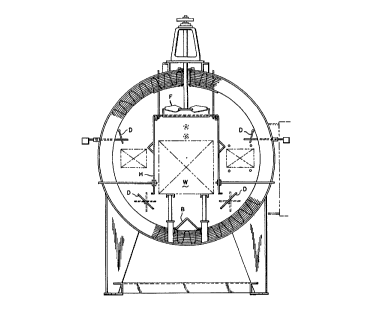
exampl0 of such an arrangement i8 shown in Figure 1 which
illustrate6 a commercially successful, prior art cylindrical
temper furnace developed by the assignee of the present in-
vention. In the cross-sectional schematic of Figure 1, the
work "W" i6 shielded on three sides by a housing "H" con-
nected to a fan plenum "P". A baffle "B" and ad~u~ta~le
dampers "D" insure an atmo~phere flow about work "~' to ef-
fect uniform convective heat transfer within a sati6factory
temperature range. Note that fan "F" i8 typically mounted
through the cylindrical furnace casing. ~hile the temper
furnace disclo~ed in Figure 1 does meet temperature unifor-
mity requirements, nevertheless the fan mounting, the baf-
fling and housing increases the furnace co~t. Also, the
pre6sure of such structure inherently effects temperature
uniformity. ID addition, the fact that the dampers must be
adju6ted sensitizes, somewhat, tbe furnace operation al-
though perhaps no more than that of the other prior art
SF-8109
arrangement~. The present invention i~ an improvement over
the Figure 1 prior srt furnace.
The prior art thu~ far described, relste6 to batch
type, positive pressure furnsces. There sre, of cour6e,
vacuum furnsces in widespread conventional use in the heat
treat field. Vacuum furnace6 snd variations thereof (such
as ion nitriders) are double wslled pressure vessel~, and
are typically formed ss cylinders with spherical ends. It
is to be appreciated that box type furn~ces repre6ent 8 con-
f~guration which cannot economically function as a pre~surevessel. In a vacuum furnace, tbe work is heated and while
under a vacuum, a treatment gas i~ backfilled into the cham-
ber to impart the desired ca~e propertiefi into the work.
The process cycle usually require~ the work to be quenched
after heating. A number of recent development6 have been
made in vacuum furnace~ to permit the work to be rapidly gas
quenched. The quench schemes u6e special nozzle di~tribu-
tion plates, baffles, dampers and the like, all of which are
designed to blast the work with high speed gss ~ets. The
concept i~ to impinge the entire ~urface of the work with
turbulent gas jets to achieve 8 heat trfln~fer rate which
approximate~ a liquid quench. U.S. patent 4,836,766 to
Jomain illustrates a typical approach where baffling in
combination with a high speed helical jet is used to
spray the work in a gas quench. Traditionally, a liquid
quench i6 effected in a separate chamber of the furnace
at atmosphere pressure.
There sre numerous, convective heat transfer flrrange-
ments in the prior art and it i6 known to use the intake of
a fan as a centrally positioned under pressure zone to cause
recircul~tion of furnace atmosphere. This is ~hown, for
example, in the baffled arrangement of the Jomsin patent.
There are variations. In U.S. Patent 4,789,333 sfisigned to
Gas Research Institute a f~ee s~anding circular jet is
developed through an orifice
~ i
.A~
S~-8109
and expanded into turbulent contact with a cylindrical ~hell
member a~ the jet trsvel6 the length of the cylindrical
~hell. At the end of the ~hell, the jet i6 redirected by a
specisl diverter plate to impinge the work and the spent jet
5 i6 then collected throu~h the under pre6sure zone to be re-
circulated. While 6uch an arrangement appears sati~factory
to effect high temperature heat tran6fer with a thin shell,
the turbulence cau6ed by the jet would have a deleterious
effect on the insulation in a temper furnace. U.S. Patent
4,395,233 to Smith et al also illustrates the use of a
central under pressure zone to cause recirculation of
forced air in a b~ing oven. However, Smith's oven is
rectilinear in configuration and this will cause turbulence
at the oven corners, and while this may be acceptable at
the relatively low pressures in an oven application, such
an arrangement is unacceptable at the high mass flow rates
required in furnace applications. None of the arrangements
is sufficient to develop the "wind" pattern required in the
heat treat furnace applications to which the present
invention is concerned.
SU~M~Y OF THE lNVENTlON
It i~ thu6 a principal object of the invention to pro-
vide 8 low cost indu6trial hest treat furnace which has im-
proved convective he~t tran6fer characteristic~.
Thi6 object along with other features of the invention
i6 achieved in an industrisl heat treat furnace which in-
cludes a cylindrical casing having a sealable door at one
open axial end while its opposite axial end is closed. An
annular fan face plate ifi concentrically positioned within
the casing and defines i) a cylindrical pre~sure zone which
extends between the fan plste and the clo~ed axial end and
ii) a cylindrical work zone which extends between the fsn
plate and the door end. The fan plate has a central opening
and an out6ide diameter wbich import~ntly i6 Bmaller than
the diameter of the ca6ing such that a non-orificing annular
A'
SF-8109
20~ ~978
spsce exi~t~ therebetween. A fsn arrsngement within the
pre66ure zone develop6 a wind ma66 pre6surized agsinst and
swirling about the cylindrical ca~ing in an e6sentially
non-turbulent manner at its interface with the ca6ing. A6
the fsn continue6 to pump and compres6 the wind mas6 in the
pres~ure zone, the wind mass flows axislly towards the door
end of the furnace through the non-orificing annular open-
in8 in the form of a 6wirling annulus of wind. Becau~e of
the non-turbulent interface, the under pre66ure zone e6tab-
lished at the central opening in the fan face plate is ef-
~ective to cau6e the inside diameter of the wind annulu6 to
expand radially inwardly in a controlled manner to uniformly
impinge the work throughout its entire length and width pri-
or to its recirculation as 6pent wind into the pressure
zone. In accordance with a more 6pecific snd important fea-
ture of the invention, the circumferentially ~wirling wind
as described i6 developed by a conventional fan having
paddle-wheel type blades which produces the de6ired circum-
ferential 6wirl but importantly doe6 60 in a wind pattern
which ha6 no si~nificant 6piral twi6t or axial component
formed by the fsn impeller.
In accordance with another 6ignificant feature of the
invention, the cylindrical work zone i6 chsracterized in
that it is completely devoid of any baffles, dampers, ~ack-
ets, ~hroud~, or sdditional pres6ure nozzles resulting in aneconomical furnace, 6tsble in operation and inherently bet-
ter able to achieve tempersture unifor~ity than prior art
devices.
In accordance with another a6pect of the invention, the
furnsce simply compri6e6 an outer steel casing formed as a
cylindrical 6hell with 8 circular end plate at one end of
the 6hell and sn snnulsr door end plate st the opposite
~hell end. A conventional wedge-shaped door sealing agsinst
the annular door end plate provides a 6imple furnsce clo-
~ure. Within the work zone a flue opening extends through
SF-8109
2~15978
the shell generally adjacent the door end plate and the only
protrusion in the work zone is a conventional work support
mechanism for supporting open meshed or closed ~ide work
baskets. Exposed blanket insulstion secured to the shell,
the end plates and the door permits the unobstructed furnace
atmosphere flow through the work zone and the aforesaid com-
bination results in an economical, easily fabricated fur-
nace.
In accordance with more specific features of the inven-
tion, a heat source i~ placed in the pres6ure zone so thatthe 6pent wind through conduction, convection and radiation
can be brought to the furnace operating ~emperature in the
pressure zone. Preferably, the source of furnace heat com-
prises a burner extending through the cylindrical casing in
the pressure zone and orientated to direct i~s products of
combustion tangential to the circumference of the cylindri-
cal casing. Alternatively, the source of heat can comprise
electric heating elements disposed within the pressure zone
and preferably in the form of an equilateral triangle con-
nected to a three phase power ~ource. Further, a heattrestin8 atmosphere ga~ can be supplied to the pressure zone
to impart certain desired physical properties to the
workpieces being heat treated 80 that the furnace can oper-
ate as an atmosphere furnace. Additionally, a cooling sr-
rangement csn be provided in the pressure zone to effectfast cooling of the workpieces in a manner similar to that
descr~bed for heating the workpieces.
In accordance with another feature of the invention, a
method and sy~tem of industrial heat tre~ting is provided by
u~ing convective heat transfer in a cylindrically sbaped
furn~ce by mean~ of the fan face plate establishing a non-
orificing annular space between the plste and the cylindri-
cal ca~ing snd then rotating the paddle bladed fan at a
speed sufficient to i) compress the w~nd mas~ radially out-
wardly again~t the cylindrical enclosure 80 that the wind
SF-8109
2~1~i978
ma6s circumferentially swirls about 6aid cylindrical enclo-
6ure in an initially stationary manner without an axial
force component, ii) force, by fan pre6~ure, the swirling
wind ma6s axislly through the annular 6pace 80 that the wind
mass, in the form of sn annulus, axially trsvels towards the
closed end of the work zone with the annulus of wind being
non-turbulent at its interface with the cylindrical enclo-
~ure snd iii) establish an under pre6sure zone at 8 central
open in the fan face plate to cau6e the wind mass to expand
radially inwardly towards the center of the work zone to
impinge the work in a uniform manner while the swirling wind
mas~ trsvels the length of the work whereby the temperature
of the wind mass i6 substantislly imparted to the work be-
fore being drawn into the under pressure zone.
In accordance wlth another specific object of the in-
vention, the tempersture uniformity of the work, whether the
work i6 placed in a clo~ed basket or a mesh basket, does not
exceed a total variation of 10~ F even through the mass flow
can vary anywhere from 250 to 3000 cubic feet per minute.
It i~ thus sn ob~ect of the pre6ent invention to pro-
vide a low-cost, e~sily sssembled industrial heat treat fur-
nace.
It i6 another ob~ect of the present invention to pro-
vide an industrial heat treat furnace with improved convec-
tive heating.
It is yet another ob~ect of the invention to provide sn
indu~trial batch type furnace which is able to maintain tem-
persture uniformity of the work within close tolerances.
Yet another object of the invention is to provide an
industrisl heat treat furnace which is able to effect con-
vective hest trsnsfer in 8 rapid manner.
Still yet snother ob~ect of the invention is to provide
8 furnace proce66 which u6e6 sn especislly formed wind flow
pattern to effect convective heat transfer with the work in
a recirculating mode.
2S~F~- 51~ 7 8
Yet another object of the invention iB to provide a
convective heat transfer industrial furnace which iB able to
heat the work by either gas or electric burners.
Still yet another ob~ect of the invention i8 to provide
an industrial heat treat furnace which is capable of circu-
lating a heat treating gas about the work.
Still another object of the invention iB to provide a
heat treating furnace which iB capable of rapid cooling of
heated work.
Another object of the invention i6 to provide a heat
treating furnace which does not use any baffles, dampers,
preg~ure nozzles and the like to effect convective he~t
transfer.
Yet snother object of the invention is to provide a
low-cost furnsce which is stable in operation.
A further object of the invention is to provide a heat
treat furnace where the maximum temperature at any point in
the wor~ during hest up does not exceed, to any eignificsnt
degree, the furnace temperature.
A still further object of the invention iB to provide a
hest tran~fer srrangement which csn effect rapid hesting snd
cooling of the work.
These and other ob~ects and sdvsntsges of the invention
will become appsrent from 8 resding of the Detailed De~crip-
tion section tsken together with the drawings which will be
descr~bed in the next section.
BRlEF D~ PTION OF THE DRAWINGS
The invention msy take phy~icsl form ~n certain psrt~
and arrsngement of psrts, a preferred embodiment of which
will be described in detsil and illustrated in the sccompa-
nying drawings which form a psrt hereof and wherein:
Figure 1 i~ a sectioned, end elevstion view of a prior
srt, cylindricsl hest treat tempering furnace;
Figure 2 i~ a sectioned, end elevation fiimilsr to Fig-
ure 1 of the furnace of the pre~ent invention;
_g_
SF-8109
2 ~ 7 8
Figure 3 i6 a longitudinally sectioned view of the fur-
nace of the present invention taken generally along lines
3-3 of Figure 2;
Figure 4 is a detsil ghowing the burner position in the
furnace of the present invention;
Figure 5 is a schematic representation showing a dia-
gram of the forces scting on the furnace atmosphere mass
flow of the present invention;
Figure 6 is a schematic, end view of a portion of the
furnace showing a modific~tion thereto;
Figure 7 is an end view of the furnsce ~howing an addi-
tional modification thereto;
Figure 8 i6 a longitudinal sectioned view of a portion
of the furnace showing the modific~tions of Figures 6 and 7;
15Figures 9 snd 10 sre graphs showing the heat profile of
work losded in solid sided and mesh sided work basket;
Figure 11 is a graph showing a cooling profile of the
present invention; snd
Figure 12 is a graph showing temperature uniformity
within the furnace at various furnace temperatures.
DETA~ DF-~CP~PTION OF THE INVENTION
Referring now to the drawings wherein the showings are
for the purpo~e of illustrating the preferred embodiment of
the invention only and not for the purpoee of limiting the
256sme, there iB shown in Figures 2 and 3 a furnace 10. In
the preferred embodiment, furnsce 10 is a low temperature
furnace using convective hest transfer to heat the work and
i6 typically ~nown ~8 a draw or temper furnace. Such fur-
naces typically operate at temperature ranges of about 1250~
F or about 800~ F.
Furnace 10 includes a cylindrical casing 12 which has
at one sxial end an open door end 13 and a closed end 14 st
its opposite axial end. An annular door cafiing 16 is se-
cured to open end 13 to define a furnace opening 17 and an
35anmll,ar closed casing 18 ~6 secured to closed end 14. All
-10 -
SF-8109
2~97~
urnace casings 12, 16 and 18 are conventional 6tructural
plates (plain, cold rolled steel) approximately 3/16 to
5/16" thick. Secured to the interior of casings 12, 16 and
18 is a vacuum-formed, ceramic fiber insulation of a rels-
tively high density, i.e. 15 lbs./ft2. The surface of theinsulation i~ sprayed with a conventional silica sand mix-
ture to make it hard and rigid. This type of insulation i~
conventionally known and readily available in the trade from
a number of sources and is thus not shown or described fur-
ther in detail herein. Insulation 20 i~ ~ecured to ca6ings12, 16 snd 18 in a conventional manner which is not shown or
described herein in detail. While insulation 20 is conven-
tional, it is a specific aspect of the invention that an
inner steel lining need not be applied to the hot face of
the insulation because, although high mass flow rates are
generated in the invention, the wind or mass flow i~ not
significantly turbulent at the in~ulation interface and will
not erode the insulation. Thus, a liner need not be used.
Closing furnace opening 17 is a conventional wedge
tight door 22. As known to those skilled in the art, cylin-
der 23 vertically raises or lowers door 22 and rollers (not
~hown) at the side~ of door 22 rolling within a cam track
(not shown) push or wedge door 22 into sealing contact with
annular door casin~ 16 to seal furnace opening 17. While
thi6 i~ a conventional door mounting, it should be noted
that insulation 20 on door casing 16 protrudes inwardly of
door 22 and this srrangement provides a recess area 25 at
open end 13 of furnace 10 Recess 25 does not have any del-
eterious effect on the wind or mass flow of the present in-
vention and there i~ no need ~o u~e a more complicated orexpensive door arrangement which would align itself with
insulation 20 on door casing 16.
Secured to door casing 16 iB a furnace support leg
~tructure 27 and secured to closed end casing 18 i~ a simi-
lar furnace support leg structure 28. Furnace 10 is not
SF-8109
2~1~97~
supported by sny structure secured to cylindricsl casing 12
to minimize expense.
Cylindrical cafiing 12, door casing 16, closed end ca6-
in~ 18 snd door 22 define a cylindrical furnace enclo6ure
5 indicsted generslly by numeral 30. Ad~scent door end 13 is
a work 6upport structure which includes a plurslity of rsil
support post~ 32 which sre secured to the interior ~urfsce
of cylindrical cssing 12 and which carry a longitudinally
extending rsil 33 which in turn csrrie6 a plurslity of slloy
roller8 34 and a chain guide 35 80 that the work can be
chsin driven on rollerB 34 into and out of furnsce enclo6ure
30 in a conventional manner. ~180 adjacent door end 13 is a
furnsce flue 40 which extends through cylindrical casing 12
snd i6 in fluid communication with furnace enclosure 30. A
damper 41 is provided in furnace flue 40 to control the ex-
haust of furnsce atmosphere and pressure within furnace en-
closure 30 in 8 known manner. Flue 40 does not adversely
affect or ~hort circuit the wind pattern developed in fur-
nace enClOBUre 30.
Concentrically positioned about longitudinal centerline
45 of furnace enclosure 30 is an snnulsr fsn fsce plate 50.
Fsn plate 50 has a circular central opening 51 which will
define an under or negstive pressure zone a8 hereafter ex-
plained. To enhsnce the under pressure zone a flange, in
the form of a curved frusto-conicsl 6ection 54 is added to
one side of fsn fsce plste 50. Again, mouth ~ection 54 is
added to enhance the funnelling aspects of the under pres-
sure zone crested by central opening 51. The outside diame-
ter of fan face plate 50 is le~ thsn the inside diameter of
circular ca~ing 12 to define a non-orificing annular space
56 therebetween. Importantly, snnular space 56 does not sct
as an orifice for reasons which will be hereafter discussed.
Fsce plate 50 iB firmly su~pended within furnace enclosure
30 at a fixed di~tance from closed end 14 by circumferen-
tia~ ly spaced thin rods (not shown) which extend through and
SF-8109
2~g78
are 6ecured to circular ca6ing 12. Alternatively, the rods
could extend through and be secured to clo6ed end ca6ing 18.
As thus fsr defined, fsn face plate 50 divides furnsce en-
clo6ure 30 into a pres6ure zone 58 which extend6 from one
6ide of fan face plate 50 to clo6ed end 14 and a work zone
60 which extend6 from the oppo6ite side of fsn face plate 50
to open end 13.
~ork zone 60 with the exception of the work support
~tructure i6 entirely free or devoid of any bsffle6, damp-
ers, nozzles or any other wind directing structure.
Workpiece~ to be tempered are conventionally placed 1006e in
work ba6ket6 or trays indicated by the dot-dash line 62
~hown in Figures 2 and 3. Baskets 62 are conventionally
known in the trade and are rectangular boxes open at the top
with a wire mesh bottom and either having closed sidewalls
or wire mesh 6idewalls. As will be explained hereafter, the
convective heat trflnsfer aspects of the invention will work
equally well whether baskets 62 have clo6ed or wire mesh
6idewalls.
Within pre6sure zone 58 snd a~ best shown in Figure~ 3
and 4, there i6 positioned a burner 64 which i6 mounted to
snd extends through cylindrical casing 12. Optionally,
there sre two burners 64 diametrically opposed to one anoth-
er and oriented to fire their products of combustion in op-
posite directions 80 that the products of combustion of one
burner add to the products of the other burner a8 they trsv-
el circumferentially sbout cylindrical casing 12. Wbile not
readily spparent in Figure 4, burner axis 65 of each burner
64 i~ oriented 80 that the products of combu6tion fire tan-
gentially about cylindrical casing 12. The vslve train for
burner 64 i~ not shown. Those s~illed in the art understflnd
from any number of vsrious valve train arrangements that it
is possible to shut off the flow of fuel to the burners and
allow air to exit burner 64 if cooling of work chamber 60 ~t
smbient temperature6 is desired. It i6 ~160 understood tbat
-13-
SF-8109
2~1597~
burner6 64 po~ses~ appropriste turndown ratios for tempera-
ture and mafi~ flow considerations. Alternatively, as dia-
grammatically illustrated in Figure 6, electric heating ele-
ments 67 could be used in place of burner 64. Electric
heating element 67 would be positioned adjacent closed ca6-
ing 18 and secured to closed casing 18. Preferably, hesting
element 67 would comprise three equsl length bayonet ele-
ment~ 69 arranged in the form of an equilateral triangle
wired in Delta or ~Jye connection to a three phase convention
power supply.
Within pressure zone 58 is a fan 70 having p~ddle wheel
blades 71. In the preferred embodiment, fan 70 has two psd-
dle wheel blades 71 connected to a shaft 73 positioned on
furnace longitudinal center line 45 and journsled in an ap-
lS propriate mounting structure 74 secured to the outside sur-
fsce of closed end cssin~ 18 and belt driven by an appropri-
ate motor 76 attsched to mounting ~tructure 74. Fan 70, per
Be i6 conventionally available from any number of fsn manu-
facturers. For the furnace sizes discussed below, fan 70
was sized for trays A-C, specifically tray B and, in the
preferred embodiment disclosed, has a rsted cspacity of 7000
CFM. In this regsrd, furnaces 10 are typically ~ized rels-
tive to the size of the work basket 62 which can be posi-
tioned within work zone 60. The etandard sizes, then, of
the work trays or bsskets 62 for the tempering furnaces of
the preferred embodiment sre as follows:
WIDTH X LENGTH X HEIGHT
A 24 30 24
B 36 48 36
C 36 72 36~72
~ 10,500
A1BO for further reference purposes, the in~ide diame-
ter of cylindricsl casing 12 including blanket insulation 20
is approximately 5' 2 5/8" snd the length of work zone 60 i6
dependent on the length of work bssket 62 but would be ap-
proximately the work bs6ket length plus an additionsl 8 to
2 ~s~589179~
10" of ~psce on either side of work basket 62. The length
of pressure zone 58 is dependent upon paddle blade size snd
the specific type and configuration of the hesting mechanism
used within pressure zone 58 snd 8180 any cooling mech~nism
employed.
OPERATION
In genersl, furnace 10 iB opersted in a conventionsl
manner. Workpieces pscked in open mesh or closed sided bss-
ket~ 62 sre conveyed into work zone 60, door 22 iB Be8led,
burners 64 are actusted and fsn 70 causes hest from burners
64 to circulste in the furnace stmosphere, i.e. wind, snd
impinge the workpieces in work bsskets 62. A thermal couple
extending through cylindricsl cssing 12 spproximstely
midway relstive to the position of work bssket 62 measures
the furnsce tempersture. When the furnace tempersture
resches the tempering tempersture the firing of the burner
64 is controlled in a conventionsl msnner snd the process
continues st this temperature for a time equal to the metsl-
lurgicsl process time, i.e. the sosk time. In the present
invention, only thermal couple 80 iB used to mes3ure furnace
tempersture becsu~e of the excellent convective heat trans-
fer charscteristic~ of the invention. This further reduces
the cost of furnace W. Optionally, an sdditional thermsl
couple csn be positioned within the work snd the process
controlled by th~t therm~l couple or by a comparison between
the temperature of the work thermal couple snd thst of the
furnace thermsl couple 80. The work i8 msintained st the
tempering temper~ture for a soak time dictsted by the met~l-
lurgicsl requirements for tbe particulsr tempering process
used. At the conclusion of the soak time, the work i8 typi-
cslly furnsce cooled whicb means that the work simply stsyswithin the furnace until it drops to a psrticular tempera-
ture whereat it i~ removed. To speed the furn~ce cool time,
fsn 76 msy be periodically -activsted with the burners, of
course, shut off. Alternatively, snd ~gain depending upon
SF-8109
2~9~8
the metallurgical proce6s, sir can be admitted through burn-
er 64 and the work cooled. In certain spplications involv-
ing brittle temper which require a fast cool cycle following
the soak time, additional provisiong msy have to be made to
furnace 10 to provide a heat 6ink within pre6sure zone 58.
One ~uch po~sible arrangement i6 a clo6ed recirculsting
cooling loop 85 a6 shown in Figure 7 which bssically com-
prises a heat exchange conduit or tubes 86 adjacent closed
end ca6ing 18 and ~ituated within pressure zone 58. Heat
exchsnge conduit 86 has an exit end 87 in fluid communica-
tion with a heat exchanger 89 where the fluid medium in heat
exchanger conduit 86 i6 cooled and then subsequently pres-
surized in a blower 90 and reintroduced into an inlet end 91
of the heat exchange conduit 86. It is a particular feature
of the invention that the incorporstion of the heat 8 ink
such as that disclosed in Figure 7 permits the heat trsnsfer
chsracteristics of the invention to have application to both
furnace heat and cool functions. Furthermore, it i6 po8Bi-
ble to add a treating gas to work zone 60 through an appro-
priste metering nozzle (not shown) in pressure zone 58 oreven through burners 64 with a conventional control arrange-
ment regulating the metering nozzle and also baffle 41 80
that the workpieces csn be appropristely heat treated by the
dissssociation of the tresting gss, etc. Thus, furnsce 10
modified to include radiant heat (in the form of indirect
hesting coils or tubes in work zone 58 not shown) cooling in
the form of the srrangement shown in Figure 7 and the intro-
duction of a heat treat gas renders the arrangement shown
suitsble for use a8 an atmosphere heat tre~ting furnsce with
or without convective heating. Cost savings for a cylindri-
cal, atmosphere heat treat furnsce when compared to conven-
tional box furnaces are significant. A~ used herein, atmo-
sphere heat treat furnaces mean furnaces operated at or
sbout standard atmosphere pressure as distingui~hed from
vacuu~ furnaces which operate st sign~ficant negative
SF-8109
20~5~78
pressure. Also as noted above, atmosphere furnaces operate
at heat treat temperature~ which are generally achieved
through radi~tion.
From streamer tests conducted about fan fsce plate 50
and from actual temperature profile tests as shown in Fig-
uree 9-11 and wind survey tests as shown in Figure 12, it iB
known that turbulent sir completely engulfs work basket 62
throughout its length and width and uniformly heats snd
cools the wor~ therein whether the baskets are closed sided
or open mesh. The operation of the invention will now be
described in sccordsnce with whst is believed to occur with-
in the furnsce.
While noted above thst conventional paddle bladed fans
are well ~nown, applicants believe that it i6 import~nt to
use such a fsn for the functioning of the invention. ~B
best shown in Figure 2, the rotation of the blsdes causes
wind moving along the face of the blades to lesve the fsn in
a generslly tangential, spinning direction as shown by arrow
95. The wind spins until contsct with cylindricsl casing
whereat it assumes a circumferential swirl about the cylin-
drical casing. This is again shown by curved arrow 95 in
Figure 5. ~his wind swirl i~ essentially normal to and
about the furnace centerline 45. At the lnterface of the
wind swirl with the casing the flow is non-turbulent. Other
types of fsns could produce turbulent flow at the casing or
could produce swirling patterns that definitely have 8 Bpi-
ral or helical motion imparted to the swirl to cau6e axisl
progression down the chsmber. It is considered an importsnt
psrt of the invention that the fsn produce 8 swirl which is
not spinning in a helix or spirsl manner. AB fan 50 contin-
ues to rotste snd more wind mass is sdded to pressure 20ne
58 the wind mass is pressurized ~nd sxially or longitudinal-
ly spreads out. In point of fact, it will dead end at one
axial side ~t end plate 18 ~nd produce turbulence therewith.
Howe-~er, the wind mas~ will travel at the other axial side
SF-8109
2 ~ 7 ~
through non-orificing space 56. In fact, the swirling wind
mass will assume the shape of an annulus equal to space 56
and will axially move, that i~ parallel to longitudinal
centerline 45, t~ward~ door end 16 of work zone ~0. It i~
to be appreciflted that the wind i~ swirling within the
annulu~ as it enters work zone snd the swirl speed can vary
anywhere from 200 to 3,000 fpm, the upper limits of which
may very well have 8 Reynoldfi number approaching that of a
~et. However the axial speed of the Bwirl i8 certainly not
that of a jet. Thus, the wind swirl is travelling axially
at a relatively low speed.
A6 ~oon as the wind mass enters work zone 60, the under
pressure zone defined by central opening 51 will cause the
swirling wind snnulus to expand radially inwardly. Refer-
ring to Figure 3, the wind annulus could be viewed as con-
taining various circular layerR, the innermost layer~ indi-
cated by arrow 98, being drawn by the under pressure almost
~mmediately into contact with basket 22, the intermediate
layer6 indicated by arrow 99 being drawn into contact with
basket 62 by the time that particular wind mas6 has reached
the middle of basket 62 while the outermost layer indicated
by arrow 100 iB pul led by the under pressure into contsct
with basket 62 adjacent casing door end 16. Of course, once
the wind annulu~ which i~ Hwirling at relatively high speed
mskes contact with basket 62, turbulence immediately occurs
and the impingement produces the desired heat exchange with
the work before the spent wind is pulled into central open-
ing 51 snd recycled or recirculated. Thu~, the fipeed of the
Bwirl i8 used to cause a very large mass of wind to react
turbulently or even violently with the work to produce high
heat transfer between wind and work.
The cylindrical shape of the case, the fan, the non-
orificing ~pace, however, are believed to be all co-acting
wlth one another to produce the wind pattern which permits
the under pressure zone to pull the wind into uniform
-1~ -
SF-8109
2 ~ 7 ~
contsct with the entire length and width of basket 62 and
thu6 the work therein. If the non-orificing 6pace acted in
the msnner of ~ jet a6 di~closed in the Hem6sth reference,
the wind would not imp~ct the work until it struck the fur-
nace door. If there ws~ significant turbulence due to a6quare cssing configuration a8 shown in Smith, the wind mass
might be short circuited, or if the wind were swirled with a
spiral motion, the axial or longitudinal ~peed would be such
that the under pre6sure zone would pull the wind annulus
into work contact only after the wind maR~ traveled 60me
distance into work zone 60. While it i~ appreciated that
~ny of 6uch arrangements, hypothetical or otherwi6e, will
place the wind into heat transfer contact with the work, the
uniformity of that contact will vary 80 that the temperature
variations schieved in the pre6ent invention msy not be as-
cert~inable.
_____________________
AB noted in the background di~cu~sion above, the prima-
ry con6ideration in any furnace defiign i~ to develop a fur-
nace enclosure which can maintain uniform furnace tempera-
ture at any point within the enclosure. That i~, the ~psce
occupied by work b~sket or tray 62 must be able to maintsin
a uniform temperature irrespective of any time or heating
rate considerations. Inherent in any furnace conetruction
are cold and hot spots where the temperature i8 Bimply
drained or the heat iB Bimply focused, the cumulative effect
of which prevents the furnace from achieving temperature
uniformity within met~llurgically specified ranges. Trsdi-
tionally, furnace manufacturers hsve claimed close tempera-
ture rsnges for their furnsce designs. However, temperaturemessuring instruments lacked the sophistication of recording
the temperature devi~tions st the tempersture ranges which
the furnace ha6 been opersted at. Recently, ~ophisticated
electronic devices have been developed which can accurately
6en6e temperature devistion~ of ~ couple of Fahrenheit
-19 -
SF-8109
2al~7s
degrees at high furnace temperature~. Using such 6t~te of
the srt temperature measuring devices, Figure 11 shows the
total variation in degree~ Fahrenheit of the temperature of
the work in the furnace when that temperature is homogenized
S or in 8 steady state. The total temperature varistion does
not exceed 10~ ~, i.e. i 5~ F. The hottest point in the
work in the steady stste condition iB indicated by reference
numeral 102 in Figure 3 and the coldest point is indicated
by reference numeral 103. It i6 believed that the hottest
point 102 i6 sffected by burner 64 generating radi~nt heat
to the innermost support po~t 32 which in turn i8 conducting
the heat to the area designated as 102. If tighter tempera-
ture variations were impo6ed, a different burner po~ition
or, alternatively, tbe electrical bayonet heating arrange-
ment di~clofied in 56 would in all probability tighten the
tempersture variation. If the cold spot designated by nu-
ntersl 103 then became the limiting factor, the fan output
could be chsnged. However, the temperature variation shown
in Figure 11 iB more than sufficient to meet stringent tem-
perature uniformity requirements impo~ed in today's temper-
ing furnace specification requirement6. Again, it i~ noted
that the absence of obstructione within work zone 60 con-
tributes to the ability of the furnace of the present inven-
tion to meet tempersture uniformity requirements since such
obstruction~ cannot function as heat sources or ~inks since
they obviously do not exi6t. The only potential obstruction
i8 the work support ~tructure which does, as di6cus6ed with
reference to Figure 11, result in the highest heated work
area. This iB a significant aspect of the invention sepa-
rate and apart frm the convective heat transfer features ofthe invention yet directly ari~ing therefrom. That iB, the
cylindrical ~hape allows the furn~ce to ~chieve inherently
superior temperature uniformity becau~e of the absence of
obstruction~ within the furn~ce and the "open" cylindrical
-20-
SF-8109
2 ~ 7 8
shape is made po6gible because of the convective heat trsn~-
fer arrangement disclosed.
Once the temperature uniformity is schieved, a secon-
dsry but important consideration, insofar a6 heating i~ con-
cerned, is the rate at which heat transfer can be effectedto reduce process time without overheating or pegging any
portion of the work. Figures 8 and 9 show the heat profile
genersted for a ~olid fiide and open or mesh sided basket~ 62
snd a typical heat tempering cycle. Note that the overshoot
of the hot spot 102 i6 very clo6e in both instances to the
final tempering temperature, i.e. either 800 or 1200~ F.
The lsg in the tempersture rise of the coldeet part of the
work is not 6ignificant since it is made up in the soak por-
tion of the temper cycle. What iB algo significant i~ that
the rate of heat transfer for the coldest part is approxi-
mately equal to that of the hest transfer rate for the hot-
test part.
Finally, Figure 10 illustrstes the cooling profile of
the invention when the work is furnace cooled. That ifi,
burner~ ~re ~imply shut off and the atmo~phere iB continued
to be circulated by fan 70. Again, the rate of cooling for
the hottest spot, 102, the coldest spot 103 and the furnace
temperature as measured by thermal couple 80, sfter sn ini-
tial discrepsncy to sccount for the spresd, is uniform.
Thu~, the grsphs, singularly and collectively, indicste that
the convective wind is uniformly impinging the work over its
entire ~urface and is achieving significantly high convec-
tlve heat transfer rates in the proces~.
Al60, it should be noted that the applications under
discussion sre limited to positive pressure furnaces snd
heat treat processes performed therein. Within the heat
trest art certain developments have been made in the vacuum
furnace area where high speed multiple ~ets ure used to cool
the workpieces to avoid liquid quench bath chsmbers. Be-
35 CaUSR of the intensity of the multiple jet impingementg,
SF-8109
2 ~ 7 8
higher heat tran6fer rate~ can be achieved in those applica-
tions thsn in the pre~ent invention. For example, heat
tran6fer rate6 for ~et cooling arrangement~ a~ high as 25-30
BTU/HR/FT2 ~ F have been achieved while the pre6ent arrange-
ment would produce cooling rate6 in tbe order of 10-15
BTU/HRtFT20 F. However, vacuum furnaces sre expen6ive, dou-
ble walled cylindrical pre~sure ve~sel6 used for certain
clo~ely controlled beat treat applications whereas atmo-
~phere or positive pres~ure type furnsces sre typically used
in heat treat spplications which do not necesEarily require
such high cooling rate~ and/or cost con~iderations preclude
high speed ~et impingement arrangement~.
The invention has been described with reference to a
preferred embodiment. Modification and alterations will
occur to others upon reading and understsnding the pre~ent
invention. It i6 our intention to include all such modifi-
cations and alterations insofsr a8 they come within the
~cope of the pre~ent invention.
-22-