Language selection

Search

Patent 2016054 Summary

Third-party information liability

Some of the information on this Web page has been provided by external sources. The Government of Canada is not responsible for the accuracy, reliability or currency of the information supplied by external sources. Users wishing to rely upon this information should consult directly with the source of the information. Content provided by external sources is not subject to official languages, privacy and accessibility requirements.

Claims and Abstract availability

Any discrepancies in the text and image of the Claims and Abstract are due to differing posting times. Text of the Claims and Abstract are posted:

  • At the time the application is open to public inspection;
  • At the time of issue of the patent (grant).
(12) Patent: (11) CA 2016054
(54) English Title: PROCESS FOR WELDING PROFILES, IN PARTICULAR PLASTIC PROFILES
(54) French Title: PROCEDE DE SOUDAGE DE PROFILES, PARTICULIEREMENT DE PROFILES EN PLASTIQUE
Status: Expired and beyond the Period of Reversal
Bibliographic Data
(51) International Patent Classification (IPC):
  • B29C 65/02 (2006.01)
  • B29C 65/20 (2006.01)
(72) Inventors :
  • BRICKENSTEIN, WOLF-JURGEN (Germany)
(73) Owners :
  • BRUGMANN FRISOPLAST GMBH
(71) Applicants :
  • BRUGMANN FRISOPLAST GMBH (Germany)
(74) Agent: SMART & BIGGAR LP
(74) Associate agent:
(45) Issued: 1999-08-03
(22) Filed Date: 1990-05-04
(41) Open to Public Inspection: 1990-11-05
Examination requested: 1997-02-25
Availability of licence: N/A
Dedicated to the Public: N/A
(25) Language of filing: English

Patent Cooperation Treaty (PCT): No

(30) Application Priority Data:
Application No. Country/Territory Date
P 39 14 826.2-45 (Germany) 1989-05-05

Abstracts

English Abstract


There is described a process for welding profiles, in
particular plastic profiles as used for windows, doors, or the
like. The two profile areas that are to be welded together are
heated to welding temperature and then joined together after
this heating process. When this is done, the face surface of
the first profile and the surface of the second profile,
transverse thereto, is heated. The heating of the second profile
is confined to a surface area which, according to position and
configuration, matches the face surface of the first profile.
The profiling of the surface of the second profile matches at
least in part the face surface profiling of the first profile.
Using this process, it is possible to weld variously shaped
profiles, in particular plastic profiles, tightly to each other.


Claims

Note: Claims are shown in the official language in which they were submitted.

-6-
THE EMBODIMENTS OF THE INVENTION IN WHICH AN EXCLUSIVE
PROPERTY OR PRIVILEGE IS CLAIMED ARE DEFINED AS FOLLOWS:
1. A method of forming a traverse joint between a
facial surface of a free end portion of a first elongated
plastic member having a predetermined outer periphery shape
and a normally closed surface of a second plastic member, the
configuration of said free end portion surface of said first
member matching that of said surface of said second plastic
member, said method comprising the steps of:
interposing a heating tool between said first and second
plastic members, said heating tool having opposite heating
surfaces configured to correspond to said configuration of
said surface of said second plastic member, a cross-sectional
area of a heating surface facing said closed surface of said
second member having an outer periphery substantially matching
that of said free end portion of said first member;
heating said facial surface of said free end portion at a
welding temperature at least at its outer periphery shape to
render it plasticized;
heating said closed surface of said second plastic member
at a welding temperature to render it plasticized only over an
area matching the outer periphery of said free end portion of
said first plastic member to form an impression of said end
portion in said closed surface at the location where said
first plastic member is to be joined to said closed surface of
said second plastic member; and

-7-
joining said heated, plasticized surfaces together to
form said traverse joint.
2. A method according to claim 1, wherein said first
and second plastic member include different outer periphery
configurations of said end portion and said facial surface.
3. A method according to claim 1, wherein said end
facial surface of said first member has a substantially
grooved outer periphery configuration and said surface of said
second member has unbroken continuous and curved
configuration.
4. A method according to claim 1, wherein said first
member and said second member are welded to each other to form
a right angle.
5. A method according to claim 4, wherein the surface
of said second member that faces said first member is
configured as a smooth unbroken surface.

Description

Note: Descriptions are shown in the official language in which they were submitted.


- 1 ~a ~ ~ 5 4
The present invention relates to a process for
welding profiles, in particular plastic profiles as used for
windows, doors, or the like, in which the two profile areas
that are to be joined to each other are heated to welding
temperature and then joined together after this heating
process.
In a customary technique for forming frame corners,
the profiles that are joined to each other are mitre cut and
welded together in the area of the mitre joint. This
technique is used both for metal profiles and for plastic
profiles.
Welding such profiles in the corner area requires
that the profiles that are to be joined each be of identical
geometrical configuration in the area of the weld. If this
requirement is not fulfilled, and different profile geometries
are used, up to now it has been necessary to match the
profiles by means of a separating cut that precedes the
welding, in such a way that after this has been done the
corner areas can be tightly welded. In many instances, it was
not possible to so configure the separating cut as to render a
tight weld possible. In this case, one frequently had to
dispense with welding and join the profiles at the corners by
means of screws.
Proceeding from this prior art, it is an object of
the present invention to provide a process of the type
described in the introduction hereto that by using it, even
profiles of differing geometries can be tightly welded to each
26221-66

5 ~
- 2 -
other.
The present invention provides a method of forming a
traverse joint between a facial surface of a free end portion
of a first elongated plastic member having a predetermined
outer periphery shape and a normally closed surface of a
second plastic member, the configuration of said free end
portion surface of said first member matching that of said
surface of said second plastic member, said method comprising
the steps of interposing a heating tool between said first and
second plastic members, said heating tool having opposite
heating surfaces configured to correspond to said configura-
tion of said surface of said second plastic member, a cross-
sectional area of a heating surface facing said closed surface
of said second member having an outer periphery substantially
matching that of said free end portion of said first member;
heating said facial surface of said free end portion at a
welding temperature at least at its outer periphery shape to
render it plasticized; heating said closed surface of said
second plastic member at a welding temperature to render it
plasticized only over an area matching the outer periphery of
said free end portion of said first plastic member to form an
impression of said end portion in said closed surface at the
location where said first plastic member is to be joined to
said closed surface of said second plastic member; and joining
said heated, plasticized surfaces together to form said
traverse joint.
The process according to the present invention makes
26221-66

6 ~ ~ 4
- 3
it possible to carry out a tight weld in order to form a
corner between two profiles that are configured in different
ways. In contrast to the formerly known welded joints, in
this instance the welded joint is not in the mitred joint but
between the normally closed surface of the second profile and
the face end of the first profile. In this regard, the face
end of the first profile is configured so as to match the
surface of the second profile that faces this end surface.
If, for example, the surface of the second profile is of an S-
shaped contour, the face surface of the first profile that isto be set upon the S-shaped surface must similarly be
configured in an S-shape. The face surface of the first
profile is normally heated completely, at least, however in
the outermost edge areas. In contrast to this, the opposite
surface of the second profile is only heated in that area, and
melted, in the case of plastic, in the area on which the face
end of the first profile is to lie after heating.
A preferred embodiment of the present invention is
described in greater detail below on the basis of the drawings
appended hereto. These drawings show the following:
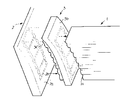
Figure 1: a perspective partial view of a part area
of the first profile and of the second profile with a hot
welding tool interposed between these;
Figure 2: a schematic side view of the profile area
during the heating phase that uses the hot welding tool.
A first profile 1 comprises a plurality of chambers
and is configured so as to have ribs and grooves on its side
26221-66

- 3a -
surfaces. The face end surface of the profile 1 is numbered
la.
A second profile 2 is shown with its face end
surface closed. The second profile has a curved surface 2a
that faces the face end la of the first profile 1.
Between the surface 2a and the face end la there is
a hot tool 3. On its right-hand side, as in figure 1, this
hot tool has a smooth curved surface 3b, the curvature of
which is identical to the curvature of the surface 2a. On the
side that faces the surface 2a, this hot tool 3 has a surface
3c, the shape of which exactly matches the outer shape of the
first profile 1.
26221-66
A

- 4 - 2~Q~"~,
~_ 26221-66
Furthermore, the spatial configuration of the side 3c corresponds
completely to the surface shape of 3b and thus both the surface
shape of the surface 2a and of the surface la. In the embodiment
shown in the drawing, these surfaces are smooth surfaces that
taper upwards in a curved shape. Of course, other surface shapes
are also possible.
Figure 2 is a schematic representation of the clamping
of the profile 1 and profile 2 on a bench, in which, in the
position shown, the hot tool lies with its surface 3c on the
surface 2a of the second profile and with its surface 3b on the
face surface la of the first profile.
The first profile is secured in the receptacle 7 of a
fixed area of the bench with the help of a schematically
represented clamping cylinder 9. In addition to the fixed area 6,
there is an area of the bench 4 that can move in the direction
indicated by the double arrow 4a, and this incorporates a
receptacle 5. The second profile 2 is locked in the receptacle 5
with the help of the clamping cylinder 8.
In the position shown, the two surfaces 3c and 3b of
the hot tool 3 heat the areas that are to be heated. The face
surface la of the first profile is heated over its entire
surface. In figure 1, the area of the surface 2a that is heated
by the surface 3c of the hot tool 3 is indicated by means of a
dashed line and is numbered 2b.
Once the areas that are to be welded have been heated,
the bench 4 moves to the left as shown in figure 2. The hot tool
3, that can be moved in the direction indicated by the double

_ 5 _ 2~
~_ 26221-66
arrow 3a, is extended out and downwards between the two profiles.
Then the bench 4 moves to the right such that the melted face
surface la and the similarly melted area 2b lie directly on one
another and can weld together.
Next, the clamping cylinders 8 and 9 are released, and
the corner can be removed.

Representative Drawing
A single figure which represents the drawing illustrating the invention.
Administrative Status

2024-08-01:As part of the Next Generation Patents (NGP) transition, the Canadian Patents Database (CPD) now contains a more detailed Event History, which replicates the Event Log of our new back-office solution.

Please note that "Inactive:" events refers to events no longer in use in our new back-office solution.

For a clearer understanding of the status of the application/patent presented on this page, the site Disclaimer , as well as the definitions for Patent , Event History , Maintenance Fee  and Payment History  should be consulted.

Event History

Description Date
Time Limit for Reversal Expired 2001-05-04
Letter Sent 2000-05-04
Grant by Issuance 1999-08-03
Inactive: Cover page published 1999-08-02
Inactive: Final fee received 1999-04-21
Pre-grant 1999-04-21
Notice of Allowance is Issued 1998-12-18
Letter Sent 1998-12-18
Inactive: Status info is complete as of Log entry date 1998-12-14
Inactive: Application prosecuted on TS as of Log entry date 1998-12-14
Inactive: Approved for allowance (AFA) 1998-11-04
Deemed Abandoned - Failure to Respond to Maintenance Fee Notice 1997-05-05
Inactive: Adhoc Request Documented 1997-05-05
Request for Examination Requirements Determined Compliant 1997-02-25
All Requirements for Examination Determined Compliant 1997-02-25
Application Published (Open to Public Inspection) 1990-11-05

Abandonment History

Abandonment Date Reason Reinstatement Date
1997-05-05

Maintenance Fee

The last payment was received on 1999-04-07

Note : If the full payment has not been received on or before the date indicated, a further fee may be required which may be one of the following

  • the reinstatement fee;
  • the late payment fee; or
  • additional fee to reverse deemed expiry.

Please refer to the CIPO Patent Fees web page to see all current fee amounts.

Fee History

Fee Type Anniversary Year Due Date Paid Date
MF (application, 8th anniv.) - standard 08 1998-05-04 1998-02-17
MF (application, 9th anniv.) - standard 09 1999-05-04 1999-04-07
Final fee - standard 1999-04-21
Owners on Record

Note: Records showing the ownership history in alphabetical order.

Current Owners on Record
BRUGMANN FRISOPLAST GMBH
Past Owners on Record
WOLF-JURGEN BRICKENSTEIN
Past Owners that do not appear in the "Owners on Record" listing will appear in other documentation within the application.
Documents

To view selected files, please enter reCAPTCHA code :


To view images, click a link in the Document Description column. To download the documents, select one or more checkboxes in the first column and then click the "Download Selected in PDF format (Zip Archive)" or the "Download Selected as Single PDF" button.

List of published and non-published patent-specific documents on the CPD .

If you have any difficulty accessing content, you can call the Client Service Centre at 1-866-997-1936 or send them an e-mail at CIPO Client Service Centre.


Document
Description 
Date
(yyyy-mm-dd) 
Number of pages   Size of Image (KB) 
Abstract 1994-02-19 1 19
Claims 1994-02-19 2 54
Drawings 1994-02-19 2 39
Description 1994-02-19 5 147
Cover Page 1994-02-19 1 15
Description 1998-10-14 6 180
Claims 1998-10-14 2 61
Cover Page 1999-07-27 1 41
Representative drawing 1999-07-27 1 11
Commissioner's Notice - Application Found Allowable 1998-12-18 1 163
Maintenance Fee Notice 2000-06-01 1 178
Correspondence 1999-04-21 1 36
Fees 1997-04-29 1 133
Fees 1996-02-26 1 45
Fees 1995-04-20 1 61
Fees 1994-04-22 1 48
Fees 1992-01-28 1 38
Fees 1993-01-29 1 33
Prosecution correspondence 1997-02-25 1 30
Prosecution correspondence 1997-03-12 1 32
Courtesy - Office Letter 1990-07-09 1 36