Sélection de la langue

Search

Sommaire du brevet 2016054 

Énoncé de désistement de responsabilité concernant l'information provenant de tiers

Une partie des informations de ce site Web a été fournie par des sources externes. Le gouvernement du Canada n'assume aucune responsabilité concernant la précision, l'actualité ou la fiabilité des informations fournies par les sources externes. Les utilisateurs qui désirent employer cette information devraient consulter directement la source des informations. Le contenu fourni par les sources externes n'est pas assujetti aux exigences sur les langues officielles, la protection des renseignements personnels et l'accessibilité.

Disponibilité de l'Abrégé et des Revendications

L'apparition de différences dans le texte et l'image des Revendications et de l'Abrégé dépend du moment auquel le document est publié. Les textes des Revendications et de l'Abrégé sont affichés :

  • lorsque la demande peut être examinée par le public;
  • lorsque le brevet est émis (délivrance).
(12) Brevet: (11) CA 2016054
(54) Titre français: PROCEDE DE SOUDAGE DE PROFILES, PARTICULIEREMENT DE PROFILES EN PLASTIQUE
(54) Titre anglais: PROCESS FOR WELDING PROFILES, IN PARTICULAR PLASTIC PROFILES
Statut: Périmé et au-delà du délai pour l’annulation
Données bibliographiques
(51) Classification internationale des brevets (CIB):
  • B29C 65/02 (2006.01)
  • B29C 65/20 (2006.01)
(72) Inventeurs :
  • BRICKENSTEIN, WOLF-JURGEN (Allemagne)
(73) Titulaires :
  • BRUGMANN FRISOPLAST GMBH
(71) Demandeurs :
  • BRUGMANN FRISOPLAST GMBH (Allemagne)
(74) Agent: SMART & BIGGAR LP
(74) Co-agent:
(45) Délivré: 1999-08-03
(22) Date de dépôt: 1990-05-04
(41) Mise à la disponibilité du public: 1990-11-05
Requête d'examen: 1997-02-25
Licence disponible: S.O.
Cédé au domaine public: S.O.
(25) Langue des documents déposés: Anglais

Traité de coopération en matière de brevets (PCT): Non

(30) Données de priorité de la demande:
Numéro de la demande Pays / territoire Date
P 39 14 826.2-45 (Allemagne) 1989-05-05

Abrégés

Abrégé anglais


There is described a process for welding profiles, in
particular plastic profiles as used for windows, doors, or the
like. The two profile areas that are to be welded together are
heated to welding temperature and then joined together after
this heating process. When this is done, the face surface of
the first profile and the surface of the second profile,
transverse thereto, is heated. The heating of the second profile
is confined to a surface area which, according to position and
configuration, matches the face surface of the first profile.
The profiling of the surface of the second profile matches at
least in part the face surface profiling of the first profile.
Using this process, it is possible to weld variously shaped
profiles, in particular plastic profiles, tightly to each other.

Revendications

Note : Les revendications sont présentées dans la langue officielle dans laquelle elles ont été soumises.


-6-
THE EMBODIMENTS OF THE INVENTION IN WHICH AN EXCLUSIVE
PROPERTY OR PRIVILEGE IS CLAIMED ARE DEFINED AS FOLLOWS:
1. A method of forming a traverse joint between a
facial surface of a free end portion of a first elongated
plastic member having a predetermined outer periphery shape
and a normally closed surface of a second plastic member, the
configuration of said free end portion surface of said first
member matching that of said surface of said second plastic
member, said method comprising the steps of:
interposing a heating tool between said first and second
plastic members, said heating tool having opposite heating
surfaces configured to correspond to said configuration of
said surface of said second plastic member, a cross-sectional
area of a heating surface facing said closed surface of said
second member having an outer periphery substantially matching
that of said free end portion of said first member;
heating said facial surface of said free end portion at a
welding temperature at least at its outer periphery shape to
render it plasticized;
heating said closed surface of said second plastic member
at a welding temperature to render it plasticized only over an
area matching the outer periphery of said free end portion of
said first plastic member to form an impression of said end
portion in said closed surface at the location where said
first plastic member is to be joined to said closed surface of
said second plastic member; and

-7-
joining said heated, plasticized surfaces together to
form said traverse joint.
2. A method according to claim 1, wherein said first
and second plastic member include different outer periphery
configurations of said end portion and said facial surface.
3. A method according to claim 1, wherein said end
facial surface of said first member has a substantially
grooved outer periphery configuration and said surface of said
second member has unbroken continuous and curved
configuration.
4. A method according to claim 1, wherein said first
member and said second member are welded to each other to form
a right angle.
5. A method according to claim 4, wherein the surface
of said second member that faces said first member is
configured as a smooth unbroken surface.

Description

Note : Les descriptions sont présentées dans la langue officielle dans laquelle elles ont été soumises.

- 1 ~a ~ ~ 5 4
The present invention relates to a process for
welding profiles, in particular plastic profiles as used for
windows, doors, or the like, in which the two profile areas
that are to be joined to each other are heated to welding
temperature and then joined together after this heating
process.
In a customary technique for forming frame corners,
the profiles that are joined to each other are mitre cut and
welded together in the area of the mitre joint. This
technique is used both for metal profiles and for plastic
profiles.
Welding such profiles in the corner area requires
that the profiles that are to be joined each be of identical
geometrical configuration in the area of the weld. If this
requirement is not fulfilled, and different profile geometries
are used, up to now it has been necessary to match the
profiles by means of a separating cut that precedes the
welding, in such a way that after this has been done the
corner areas can be tightly welded. In many instances, it was
not possible to so configure the separating cut as to render a
tight weld possible. In this case, one frequently had to
dispense with welding and join the profiles at the corners by
means of screws.
Proceeding from this prior art, it is an object of
the present invention to provide a process of the type
described in the introduction hereto that by using it, even
profiles of differing geometries can be tightly welded to each
26221-66

5 ~
- 2 -
other.
The present invention provides a method of forming a
traverse joint between a facial surface of a free end portion
of a first elongated plastic member having a predetermined
outer periphery shape and a normally closed surface of a
second plastic member, the configuration of said free end
portion surface of said first member matching that of said
surface of said second plastic member, said method comprising
the steps of interposing a heating tool between said first and
second plastic members, said heating tool having opposite
heating surfaces configured to correspond to said configura-
tion of said surface of said second plastic member, a cross-
sectional area of a heating surface facing said closed surface
of said second member having an outer periphery substantially
matching that of said free end portion of said first member;
heating said facial surface of said free end portion at a
welding temperature at least at its outer periphery shape to
render it plasticized; heating said closed surface of said
second plastic member at a welding temperature to render it
plasticized only over an area matching the outer periphery of
said free end portion of said first plastic member to form an
impression of said end portion in said closed surface at the
location where said first plastic member is to be joined to
said closed surface of said second plastic member; and joining
said heated, plasticized surfaces together to form said
traverse joint.
The process according to the present invention makes
26221-66

6 ~ ~ 4
- 3
it possible to carry out a tight weld in order to form a
corner between two profiles that are configured in different
ways. In contrast to the formerly known welded joints, in
this instance the welded joint is not in the mitred joint but
between the normally closed surface of the second profile and
the face end of the first profile. In this regard, the face
end of the first profile is configured so as to match the
surface of the second profile that faces this end surface.
If, for example, the surface of the second profile is of an S-
shaped contour, the face surface of the first profile that isto be set upon the S-shaped surface must similarly be
configured in an S-shape. The face surface of the first
profile is normally heated completely, at least, however in
the outermost edge areas. In contrast to this, the opposite
surface of the second profile is only heated in that area, and
melted, in the case of plastic, in the area on which the face
end of the first profile is to lie after heating.
A preferred embodiment of the present invention is
described in greater detail below on the basis of the drawings
appended hereto. These drawings show the following:
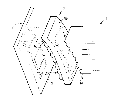
Figure 1: a perspective partial view of a part area
of the first profile and of the second profile with a hot
welding tool interposed between these;
Figure 2: a schematic side view of the profile area
during the heating phase that uses the hot welding tool.
A first profile 1 comprises a plurality of chambers
and is configured so as to have ribs and grooves on its side
26221-66

- 3a -
surfaces. The face end surface of the profile 1 is numbered
la.
A second profile 2 is shown with its face end
surface closed. The second profile has a curved surface 2a
that faces the face end la of the first profile 1.
Between the surface 2a and the face end la there is
a hot tool 3. On its right-hand side, as in figure 1, this
hot tool has a smooth curved surface 3b, the curvature of
which is identical to the curvature of the surface 2a. On the
side that faces the surface 2a, this hot tool 3 has a surface
3c, the shape of which exactly matches the outer shape of the
first profile 1.
26221-66
A

- 4 - 2~Q~"~,
~_ 26221-66
Furthermore, the spatial configuration of the side 3c corresponds
completely to the surface shape of 3b and thus both the surface
shape of the surface 2a and of the surface la. In the embodiment
shown in the drawing, these surfaces are smooth surfaces that
taper upwards in a curved shape. Of course, other surface shapes
are also possible.
Figure 2 is a schematic representation of the clamping
of the profile 1 and profile 2 on a bench, in which, in the
position shown, the hot tool lies with its surface 3c on the
surface 2a of the second profile and with its surface 3b on the
face surface la of the first profile.
The first profile is secured in the receptacle 7 of a
fixed area of the bench with the help of a schematically
represented clamping cylinder 9. In addition to the fixed area 6,
there is an area of the bench 4 that can move in the direction
indicated by the double arrow 4a, and this incorporates a
receptacle 5. The second profile 2 is locked in the receptacle 5
with the help of the clamping cylinder 8.
In the position shown, the two surfaces 3c and 3b of
the hot tool 3 heat the areas that are to be heated. The face
surface la of the first profile is heated over its entire
surface. In figure 1, the area of the surface 2a that is heated
by the surface 3c of the hot tool 3 is indicated by means of a
dashed line and is numbered 2b.
Once the areas that are to be welded have been heated,
the bench 4 moves to the left as shown in figure 2. The hot tool
3, that can be moved in the direction indicated by the double

_ 5 _ 2~
~_ 26221-66
arrow 3a, is extended out and downwards between the two profiles.
Then the bench 4 moves to the right such that the melted face
surface la and the similarly melted area 2b lie directly on one
another and can weld together.
Next, the clamping cylinders 8 and 9 are released, and
the corner can be removed.

Dessin représentatif
Une figure unique qui représente un dessin illustrant l'invention.
États administratifs

2024-08-01 : Dans le cadre de la transition vers les Brevets de nouvelle génération (BNG), la base de données sur les brevets canadiens (BDBC) contient désormais un Historique d'événement plus détaillé, qui reproduit le Journal des événements de notre nouvelle solution interne.

Veuillez noter que les événements débutant par « Inactive : » se réfèrent à des événements qui ne sont plus utilisés dans notre nouvelle solution interne.

Pour une meilleure compréhension de l'état de la demande ou brevet qui figure sur cette page, la rubrique Mise en garde , et les descriptions de Brevet , Historique d'événement , Taxes périodiques et Historique des paiements devraient être consultées.

Historique d'événement

Description Date
Le délai pour l'annulation est expiré 2001-05-04
Lettre envoyée 2000-05-04
Accordé par délivrance 1999-08-03
Inactive : Page couverture publiée 1999-08-02
Inactive : Taxe finale reçue 1999-04-21
Préoctroi 1999-04-21
Un avis d'acceptation est envoyé 1998-12-18
Lettre envoyée 1998-12-18
Inactive : Renseign. sur l'état - Complets dès date d'ent. journ. 1998-12-14
Inactive : Dem. traitée sur TS dès date d'ent. journal 1998-12-14
Inactive : Approuvée aux fins d'acceptation (AFA) 1998-11-04
Réputée abandonnée - omission de répondre à un avis sur les taxes pour le maintien en état 1997-05-05
Inactive : Demande ad hoc documentée 1997-05-05
Exigences pour une requête d'examen - jugée conforme 1997-02-25
Toutes les exigences pour l'examen - jugée conforme 1997-02-25
Demande publiée (accessible au public) 1990-11-05

Historique d'abandonnement

Date d'abandonnement Raison Date de rétablissement
1997-05-05

Taxes périodiques

Le dernier paiement a été reçu le 1999-04-07

Avis : Si le paiement en totalité n'a pas été reçu au plus tard à la date indiquée, une taxe supplémentaire peut être imposée, soit une des taxes suivantes :

  • taxe de rétablissement ;
  • taxe pour paiement en souffrance ; ou
  • taxe additionnelle pour le renversement d'une péremption réputée.

Veuillez vous référer à la page web des taxes sur les brevets de l'OPIC pour voir tous les montants actuels des taxes.

Historique des taxes

Type de taxes Anniversaire Échéance Date payée
TM (demande, 8e anniv.) - générale 08 1998-05-04 1998-02-17
TM (demande, 9e anniv.) - générale 09 1999-05-04 1999-04-07
Taxe finale - générale 1999-04-21
Titulaires au dossier

Les titulaires actuels et antérieures au dossier sont affichés en ordre alphabétique.

Titulaires actuels au dossier
BRUGMANN FRISOPLAST GMBH
Titulaires antérieures au dossier
WOLF-JURGEN BRICKENSTEIN
Les propriétaires antérieurs qui ne figurent pas dans la liste des « Propriétaires au dossier » apparaîtront dans d'autres documents au dossier.
Documents

Pour visionner les fichiers sélectionnés, entrer le code reCAPTCHA :


Pour visualiser une image, cliquer sur un lien dans la colonne description du document. Pour télécharger l'image (les images), cliquer l'une ou plusieurs cases à cocher dans la première colonne et ensuite cliquer sur le bouton "Télécharger sélection en format PDF (archive Zip)" ou le bouton "Télécharger sélection (en un fichier PDF fusionné)".

Liste des documents de brevet publiés et non publiés sur la BDBC .

Si vous avez des difficultés à accéder au contenu, veuillez communiquer avec le Centre de services à la clientèle au 1-866-997-1936, ou envoyer un courriel au Centre de service à la clientèle de l'OPIC.


Description du
Document 
Date
(aaaa-mm-jj) 
Nombre de pages   Taille de l'image (Ko) 
Abrégé 1994-02-19 1 19
Revendications 1994-02-19 2 54
Dessins 1994-02-19 2 39
Description 1994-02-19 5 147
Page couverture 1994-02-19 1 15
Description 1998-10-14 6 180
Revendications 1998-10-14 2 61
Page couverture 1999-07-27 1 41
Dessin représentatif 1999-07-27 1 11
Avis du commissaire - Demande jugée acceptable 1998-12-18 1 163
Avis concernant la taxe de maintien 2000-06-01 1 178
Correspondance 1999-04-21 1 36
Taxes 1997-04-29 1 133
Taxes 1996-02-26 1 45
Taxes 1995-04-20 1 61
Taxes 1994-04-22 1 48
Taxes 1992-01-28 1 38
Taxes 1993-01-29 1 33
Correspondance de la poursuite 1997-02-25 1 30
Correspondance de la poursuite 1997-03-12 1 32
Courtoisie - Lettre du bureau 1990-07-09 1 36