Note: Descriptions are shown in the official language in which they were submitted.
2016237
Case NF 89
HOT-AIR FURNACE
FIELD OF THE INVENTION
This invention relates to a hot-air furnace suitable for
hot-air heating of horticultural greenhouses in par-
ticular, ordinary buildings and factories, as well as a
heat source for drying facilities in a hot-air or hot-
blast system, and the like.
BACKGROUND OF THE INVENTIO~
Hot-air furnaces or hot-air heaters as above can be
classified broadly into the following three types:
(1) a furnace, drum unified type;
(2) a furnace, combustion chamber and smoke tube
type;
(3) a furnace, combustion chamber and heat ex-
changer type.
These three types are shown in Figs. 12 (a) to (f) of the
accompanying drawings.
The furnace, drum unified type is shown in Fig. 12 (a),
in which 41 denotes a drum, 42 a burner, 43 a flame, 44
a fan, 45 a discharge port for hot air, and 46 a thermal
resisting filler. The flame 43 is generated by the
burner 42 at the lower part of the drum 41, and combus-
tion gas is heat-exchanged and loses its temperature
while passing through the drum 41 and the heat resisting
filler 46 at the upper part thereof, and is exhausted
from an exhaust port 47. Air flow taken into the drum
41 by the fan 44, in the direction of the white arrow I,
is heated while going around the drum 41, and is dis-
charged in the direction of the white arrow II from the
discharge port 45, and is then supplied~to a desired
~ 2016237
place, for example, into a greenhouse, as hot air.
Figs. 12(e) and (f) are sections along the lines E-E and
F-F in Fig. 12(a). In Fig. 12, solid line arrows show
combustion gas flow and the white arrows, as mentioned
above, air flow.
A furnace, combustion chamber and smoke tube type is
shown in Figs. 12(b) and (c). The same reference
numerals are applied to the same parts as are shown in
Fig. 12(a), and 48 denotes smoke tubes. Air taken in by
the fan 44 is heat-exchanged and heated by the combus-
tion chamber 50 and the smoke tubes 48, and is dis-
charged from the discharge port 45. Accordingly, a hot-
air furnace of this type is called a furnace, combustion
chamber and smoke tube type.
Among the hot-air furnaces of the types described, the
one shown in Fig. 12(a) was developed by the present
applicant and was published in Japanese Patent Publica-
tion (Unexamined) No. 297631/1988. A furnace, combus-
tion chamber and heat exchanger type is shown in Fig.
12(d), and the same reference numerals are applied to
the same parts as are shown in Fig. 12(a). Further, 49
denotes a heat-exchanger and 50 the combustion chamber.
Combustion gas generated in the combustion chamber 50 is
exhausted from thé exhaust port 47 via the heat-ex-
changer 49. While air taken in by the fan 44 as shown
by the white arrow I is heat-exchanged and heated by the
heat-exchanger 49, then heated further around the
combustion chamber 50, and finally discharged in the
direction of white arrow II from the discharge port 45.
SUMMARY OF THE INVENTION
In the combustion chamber of the conventional drum, the
temperature gets high at the front part of the flame
- 201~37
-
axis and, depending on the mode of use, cracks, expan-
sion and oxidation may occur due to high temperature or
heat fatigue, and there is the possibility of the drum
being damaged. Furthermore, a considerable length is
necessary along the flame axis, and consequently the
diameter and length of the drum must also be sufficient-
ly long.
In the construction with a heat exchanger, it is desira-
ble to reduce more the depth, width and height, as well
as to enhance further the heat transfer efficiency (high
heat transmission) by accelerating turbulent flow of the
air flow.
In any of the above-mentioned three furnace types,
because the exhaust port is fixed at the upper part of
the drum, the direction of exhaust is restricted, and
because the fan is mounted at the upper part of the
drum, there is a limitation on the manner of taking in
the air. Thç drum construction, having numerous projec-
ting parts, is subject to substantial ventilation
resistance, and it interrupts the flow of air to be
heated. Moreover, stagnant locations are inevitably
brought about in the air flow, and a large heat transfer
area is necessary. Damage due to local thermal fatigue
and corrosion may easily occur. Naturally, the power
for ventilation is bound to be large to secure required
wind volume, which is likely to raise the noise level.
It is an object of preferred embodiments of this inven-
tion to provide a hot-air furnace wherein set-up posi-
tions of a combustion chamber, a heat exchanger, an
exhaust port and a fan as well as drum construction are
improved, durability is maintained and the heat transfer
efficiency is enhanced, and an air-intake port, an
2~16237
exhaust port, the drum construction, etc. are improved
so that setting up may freely be designed.
According to the present invention there is provided a
hot-air furnace comprising: a long-flame burner for
combustion gas or liquid fuel, a combustion chamber
connected to the burner and having its length (1) and
width ~w1) in the relationship of w1~l, a blower located
above or below a drum, a heat exchanger which is located
above the combustion chamber, having inside thereof a
gas flow guide plate which guides combustion gas flow
discharged from the combustion chamber to the heat
exchanger, and having its width (w2) and length (1) in
the relationship of w2<1, an exhaust port, located at
the front or rear, right or left-hand side or on the top
side above said heat exchanger, for exhausting the
combustion gas flow, a casing having a drum which
integrally connects the combustion chamber and the heat
exchanger and an air flow guide and directing plate
which covers the drum and a radiant heat absorber plate,
and the blower, wherein a discharge port is mounted such
that the direction of discharging air flow corresponds
to the up or down position of the blower.
By having a small-diameter, long-axis combustion chamber
and directing air flow at right angles to the combustion
chamber, high-temperature gas uniformly contacts the
inside walls of the combustion chamber and, while the
air flow can contact at almost right angles on an
average and at high speed all over the outside walls of
the combustion chamber, the temperature on the walls of
the combustion chamber can be kept uniform with the
cooling and heat transfer efficiencies improved, so that
unusual localized heating can be avoided. Also, damage
due to cracks, and expansion because of oxidation at
- ~16237
.
high temperature and heat fatigue can be prevented,
while high furnace load and high surface load can be
realized.
As the heat exchanger is preferably thin and structured
longitudinally long, its depth and width can be reduced,
and by changing the height, heat output and thermal
efficiency can be freely determined and adjusted.
Further, as the heat exchanger preferably has the flat-
plate type heat exchanging surface structure, it is
possible to provide the surface with dimples or folds to
accelerate turbulent flow of the combustion gas and air
flow, so that high heat transfer can be performed. And,
because of occurrence of turbulent flow in the combus-
tion gas part of the heat exchanger, it is easy to set
up a guide plate for rapid rising of gas flow, improving
heat transfer from gas, and the exhaust port can be
placed at the top most part of the drum, allowing any
sideward, upward or lateral direction with little
restriction on the exhausting direction.
When an exhaust port is mounted on the burner side, so-
called FF (Forced Flue) system of air supply and gas
exhaust can be easily employed. The drum construction
has fewer projections which resist the air flow so that
ventilation resistance can be reduced, and large wind
volume, reduction in noise, and economy of power for
ventilation can be easily realized, and high speed air
flow can be given to the heat transfer surface so that
high heat transmission can be realized, and furthermore,
a blower or fan can be freely placed, either at the
upper part or the lower part of the furnace.
2016237
Other objects, features and advantages of the present
invention will become more fully apparent from the
following detailed description of the preferred embodi-
ments, the appended claims and the accompanying
drawings.
BRIEF DESCRIPTION OF THE DRAWINGS
In the accompanying drawings, in which like reference
characters in the same or different Figures indicate
like parts:
Fig. 1 illustrates an embodiment of a hot-air
furnace of the present invention wherein
Fig. l(a) is a front view, Fig. l(b) a sec-
tional view along the line B-B of Fig.
l(a), Fig. l(c) a sectional view along the
line C-C of Fig. l(a), and Fig. l(d) a
sectional view along the line D-D of Fig.
l(a);
Figs. 2(a) to (g) are sectional views of various
embodiments of the combustion chamber
structure of the hot-air furnace of Fig. l;
Fig. 3 illustrates a heat exchanger structure,
wherein Fig. 3(a) is a front view,
Fig. 3(b) a side view, Fig. 3(c) a front
view of a variation, Fig. 3(d) a side view
thereof, Fig. 3(e) a front view of another
variation and Fig. 3(f) a side view there-
of;
Figs. 4(a) to (c) are side sectional views o~
different drum embodiments for the hot-air
furnace of Fig. l;
Figs. 5(a) to (j) are views illustrating various
embodiments of projecting parts on the
sides of the heat exchanger;
- 20I~23~
.
Fig. 6 shows different arrangements for the ex-
haust port, wherein Fig. 6(a) is a front
view of setting up thereof on the front or
rear side of the heat exchanger, Fig. 6(b)
a front view of setting up thereof on the
lateral side of the heat exchanger,
Fig. 6(c) a side view of the embodiment in
Fig. 6(b), Fig. 6(d) is a front view of
setting the same upon the top of the heat
exchanger and Fig. 6(e) is a side view of
the embodiment in Fig. 6(d);
Figs. 7 (a) to (c) are front views of three hot-
air furnaces of the present invention show-
ing different arrangements of the blower
and the discharge port;
Fig. 8 is a side sectional view of the periphery
of the drum;
Fig. 9 shows a ventilation and heat transfer pipe
arrangement wherein Fig. 9(a) is a side
view, Fig. 9(b) a front view, Fig. 9(c) a
front view showing combustion gas flow, and
Fig. 9(d) a top view;
Fig. 10 shows multiple unit furnaces in which two
or more hot-air furnaces are connected
together, Fig. lO(a) being a front section-
al view of a twin connection embodiment,
Fig. lO(b) a front view of the twin connec-
tion embodiment, Fig. lO(c) a top view of
the twin connection embodiment, Fig. lO(d)
a top view of a triple connection embodi-
ment, and Fig. lO(e) a top view of a quad-
ruple connection embodiment;
Fig. 11 is a chart showing an example of the out-
put control range of the twin connection
embodiment of Figs. lO(a) to (c); and
2~6237
Fig. 12 shows prior art furnaces, wherein Fig.
12(a) is a front sectional view of the
furnace and duct unified type, Figs. 12(b)
and (c) front sectional views of the fur-
nace, duct and smoke tube type, Fig. 12(d)
a front sectional view of the furnace, duct
and heat exchanger type, Fig. 12(e) a sec-
tional view along the line E-E of Fig.
12(a), and Fig. 12tf) a sectional view
along the line F-F of Fig. 12(a).
DETAILED DESCRIPTION OF THE PREFERRED EMBODIMENTS
Various embodiments of the invention will now be ex-
plained in detail with reference to the drawings.
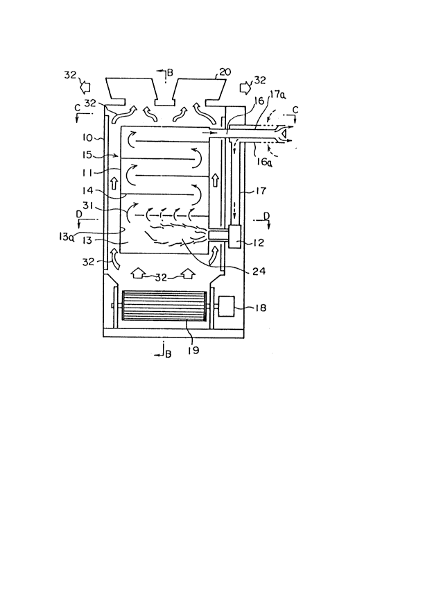
An embodiment of this invention is shown in Fig. 1,
wherein Fig. l(a) is a front view, Fig. l(b) a sectional
view along the line B-B of Fig. l(a), Fig. l(c) a
sectional view along the line C-C of Fig. l(a), and Fig.
l(d) a sectional view along the line D-D of Fig. l(a).
In Fig. 1, 10 is a casing, 11 a drum, 12 a burner, 13 a
combustion chamber, 14 a gas flow guide plate, 15 a heat
exchanger, 16a a combined air supply and exhaust duct
from around the periphery of which air for combustion is
supplied and led to an air supply duct 17 An exhaust
port 16 is connected to an inner duct 17a of the air
supply and exhaust duct 16a, and cooled combustion gas
is exhausted through the inner duct 17a of this air
supply and exhaust duct 16a. A fan motor 18 drivingly
rotates a blower 19 to draw air in through suction ports
21 and discharge hot air through discharge port 20. This
air flow passes through an air flow guide and directing
plate 23 while passing over a radiant heat absorber
plate 22 and projecting parts 25. The solid line arrows
indicate combustion gas flow 31 from flame 24, the white
2Q~237
\
arrows denote air flow 32, and the broken line arrows
indicate air being taken in for combustion. Combustion
gas flow 31 generated in the combustion chamber 13 flows
almost uniformly in the upper part of the combustion
chamber 13 and above the side portion 13a of the com-
bustion chamber, and then is directed to the heat
exchanger 15 by the gas flow guide plate 14, and ex-
hausted to the outside through the exhaust port 16. The
air taken in through the suction port 21 is directed by
the blower 19 as air flow 32 from the lower part of the
combustion chamber 13 to the upper part thereof, and
after being heated by the combustion chamber 13 and the
heat exchanger 15, air flow 32 is discharged from the
discharge port 20.
The embodiment shown in Fig. 1 is of a structure in
which:
(i) there is a long-flame typç burner 12 for
combusting gas or liquid fuel;
(ii) a combustion chamber 13 is small in diameter
and long-bodied, and is located at the lower
part of a drum 11;
(iii) a heat exchanger 15 is located above the
combustion chamber 13 and is thin and flat-
shaped;
(iv) an exhaust part consisting of an exhaust port
16 corresponds to a thin, flat and long-
shaped drum structure placed above the heat
exchanger 15;
(v) a blower 19 is placed below the drum 11; and
(vi) hot blast or air is discharged from the posi-
tion opposite to the blower location, i.e.
the air is discharged from the upper part of
the drum.
~016237
-- 10 --
Referring to Fig. l(c) and Fig. l(d), the relation of
width w2 of the heat exchanger 15, which has on its
surface the projecting parts 25 forming dimples or
folds, and width wl of the combustion chamber 13 were
selected to be w2 < or = w~, and width w1 of the combus-
tion chamber was set to be l/w1 > or = 1.5, where 1 is
the common length of the heat exchanger 15 and the
combustion chamber. This design makes it possible to
render a hot-air furnace according to this invention
flat and thin-shaped.
The values of above-mentioned w1,w2 and 1 were as follows
in two specific embodiments:
Embodiment I II
w2 70 mm 100 mm
w1 200 mm 250 mm
1 600 mm 740 mm
The heat outputs obtained in the embodiments I and II
were 20,000 [kcal/h~ and 32,000 [kcal/h] respectively,
at 89% thermal efficiency.
In Fig. 2, the structure of the combustion chamber and
various variations thereof are illustrated. The cross
section shape of the combustion chamber 13 is almost
round as shown in Fig. 2(f), or oval or elliptical as
shown in Fig. 2(g). In Figs. 2(a) to (e), various
longitudinal sections of the combustion chamber 13 are
shown. Fig. 2(a) illustrates a basic shape, that is, a
rectangular shape of the combustion chamber 13, wherein
12a is a burner port. Other illustrations in Figs.
2(b), (c) and (d) are variations of the combustion
chamber 13 in Fig. 2(a), wherein its corners are notched
or rounded, to provide a somewhat elliptical shape. In
the variation shown in Fig. 2(e), both ends of the
-
- 201623~
combustion chamber 13 are tapered. From the viewpoint
of keeping uniform heat transfer and relieving local
heat stress, it is desirable to have the corners
rounded, such rounded corners enabling easy manufacture
with press metal molds.
With the above structure of the combustion chamber 13,
uniform heating can be attained with less heat stress
and less damage due to heat fatigue. Selection of
material for a combustion chamber may be done freely,
taking into consideration combustion chamber load, the
surface temperature of the combustion chamber, and
economy. The air flow can be directed at right angles
to the combustion chamber and circulated at high speed,
and owing to good cooling conditions, without use of
high-grade thermal resisting steel, thus making a design
fit for practical use possible.
As shown in Fig. 2(f) and Fig. 2(g), the combustion
chamber 13 has an almost circular section with its
height h1 being equal to its width w1 (i.e. h1=w1). But
it can be also arranged so that hl>wl, in which case the
combustion chamber 13 has an elliptical section with
width wl of the combustion chamber being narrowed, and
therefore width W1~ of the air flow guide and directing
plates 23 at the combustion chamber shown in these
figures can be also narrowed, and a more compact design
is realized.
Various embodiments of the heat exchanger 15 for attain-
ing effective heat transfer will now be described in
greater detail referring to Figs. 3, 4 and 5. Fig. 3
illustrates the structure of a heat exchanger, wherein
Fig. 3(a) is a front view, and Fig. 3(b) a side view;
Figs. 3(c) and (e) are front views of variations, and
2Q16237
- 12 -
Figs. 3(d) and (f) side views of these variations.
Figs. 4(a), (b) and (c) are respective side views of
different drums in vertical section, each showing a
different construction. Figs. 5(a) to (j) are illustra-
tions of various patterns of dimples or folds formed onthe sides of the heat exchanger 15.
Width w2 of the heat exchanger 15 may be selected, as
shown in Figs. 4(a), (b) and (c), relative to the width
w1 of the combustion chamber 13, interval space width wl'
of the air flow guide and directing plate 23 at the
combustion chamber part, and width w2' of the said air
flow guide and directing plate 23 at the heat exchanger
part, so that generally w1<w1', w2<w2', w2 < or = w1
W2~ < or = w1l; in the embodiment shown in Fig. 4(a)
wz=w1; in Fig. 4(b) embodiment W2<W~; and in the tapered
embodiment shown in Fig. 4(c), both w2 and w2' become
narrower approaching the exhaust part, and even if the
combustion gas is cooled and its volume is reduced, heat
exchange is effected at an angle ~ enabling the gas to
flow at substantially constant speed so as to keep
effective heat transfer.
Specific values of examples of the above-mentioned w1,w2,
w1l, w2' are given in the following table:
Embodiments I II
w1 200 mm 250 mm
wz 70 mm loo mm
wl' 340 mm 410 mm
w2' 200 mm 280 mm
The heat outputs obtained in these embodiments I and II
were 20,000 [kcal/h] and 32,000 [kcal/h] respectively,
at 89% t~ermal efficiency.
2~16237
As Fig. 3(a) illustrates, the edge 13a of the combustion
chamber which faces the burner is located in the posi-
tion most easily affected by the flames and vulnerable
to damage by burning. Accordingly, as shown in the side
view of the variation of Figs. 3(c) and (d), the part
marked with a reference S is of a structure which
disperses the flames along the side walls of the combus-
tion chamber and directs them to the heat exchanger, so
as to obtain uniform heat transfer effect, prevent local
overheating and reduce the possibility of the thermal
stress being generated. The variation shown in
~igs. 3(e) and (f) is similar to that shown in Fig.
4(c).
Figs. 5(a) to (j) show shapes and arrangements of the
projecting parts 25 on the surface of the heat exchanger
15. Basic shapes are shown in Figs. 5(a), (d), (g) and
(j), and variations of the first three thereof are shown
respectively in Figs. 5(b) and (c), Figs. 5(e) and (f),
Figs. 5(h) and (i). These projecting parts 25 cause
turbulent flows when combustion gas and air flow,
respectively, are passing over the wall surface of the
heat exchanger 15 and enhance heat transfer. In par-
ticular, they play an important role in removing boun-
dary layers in a flat-plate heat exchanger as employed
in this invention. Each variation shows a specific
result of a specific manufacturing process. The projec-
ting parts 25, which are shown as lines of ridges, or
crosses, or diamonds, or pips etc. are preferably
distributed in a pattern over the entire side walls of
the heat exchanger 15 above the combustion chamber 13.
The exhaust part consisting of the exhaust port 16 is
shown in Fig. 6, wherein Fig. 6(a) is a front view
illustrating a set-up on the upper front or rear side,
201623~
Fig. 6(b) is a front view illustrating a set-up on the
upper right or left-hand side, Fig. 6(c) is a side view
of the embodiment of Fig. 6(b), Fig. 6(d) is a front
view illustrating a set-up on the top side, Fig. 6(e) is
a side view of the embodiment of Fig. 6(d), and the
solid line arrow shows exhaust gas flow. The exhaust
port 16 is located at the position indicated by the
solid line, but it may also be mounted at the position
indicated by the broken line. As shown in the illustra-
tions, the exhaust port 16 can be placed as desired, inthe front or rear side, right or left-hand side, or on
the top side. Air supply and gas exhaust by FF (Forced
Flue) system can be also done as shown in the front view
of Fig. l(a). As the exhaust port can be set up on the
top side or at any of the upper four positions, there is
less crosscut for connection to an exhaust chimney at
the time of installation of a hot-air furnace, allowing
easier installation.
Arrangements according to the invention of a blower, an
air suction port and an air discharge port are shown in
Fig. 7, wherein Figs. 7(a), (b) and (c) are front views
of respective variations. The blower 19 can take the
form of crossflow, duplex sirocco fan system, or of a
plurality of propellers. The suction port 21 is mounted
at the upper or lower part adjacent where the blower 19
is placed, and the discharge port 20 is located at the
lower or upper part opposite to the position where the
blower 19 is located. The heat-exchanged air flow
discharges from the discharge port 20 as hot air or
blast. Where inexpensive sirocco fans are used side by
side, the air can be distributed uniformly and there is
an advantage of having less height than in the case of
a single fan. A forced ventilation system is applied
against and over the heat exchanger 15, and it can be an
2~16237
- 15 -
upwardly discharging or downwardly discharging type
depending on the end use. Air can flow evenly, ven-
tilation resistance and ventilation power can be
reduced, and a large amount of wind or air flow can be
obtained with low noise.
The casing or outer covering 10 is flat, long and
rectangular-shaped, and by rounding the corners thereof,
a simple and attractive design is obtained.
As described above, the position of the blower and that
of the discharge port depend on each other, and manufac-
turing of products of either upwardly discharging or
downwardly discharging type according to the need is
possible. Also, a duct connect type can advantageously
be provided by having a flange-typed exhaust part.
Fig. 8 is a drawing to explain an embodiment for utiliz-
ing radiant heat transfer around the combustion chamber.
The combustion chamber 13 is kept at the highest temper-
ature condition in the heat exchanger 15 and is capable
of positive heat transfer. In selecting material for
the combustion chamber, it is desirable to reduce
temperature as low as possible and accelerate heat
transfer. Therefore, by painting black-colored radia-
tion accelerator agent on the surface of the combustion
chamber 13, and also by applying paints which easily
absorb radiant heat to radiant heat absorber plate 22
opposite and partly surrounding the combustion chamber,
radiant heat is absorbed; and further, by transferring
heat to air by way of convection effect, more radiation
of heat can be realized in the combustion chamber. The
air flow 32 directed by the radiant heat absorber plate
22 is separated into the outside air way 34 and the
inside air way 33. With this arrangement, when the
2al~2~
- 16 -
amount of heat transfer in the combustion chamber 13 is
large, the burden to the heat exchanger will be reduced,
and thus the size of the heat exchange can be made
smaller and the whole structure more compact.
Methods using ventilation and heat transfer pipes to mix
air flows, accelerate heat transfer and prevent damage
by burning are illustrated in Fig. 9, wherein Fig. 9(a)
is a side view, Fig. 9(b) a front view, Fig. 9(c) a
front view showing the combustion gas flow 31 indicated
by the solid line arrows, and Fig. 9(d) a plan view. As
shown in Figs. 9(a) to (d), the ventilation and heat
transfer pipes 26 are disposed obliquely and upwardly of
the combustion chamber 13 and alternately pass through
the heat exchanger 15, being directed from right to the
upper left, or from left to the upper right as in
Fig. 9(a). As the combustion gas flow is directed at
right angles to the external periphery of the ventila-
tion and heat transfer pipes 26 as shown in Fig. 9(c),
good heat transfer is obtained from the hot combustion
gas. Also, if a suitable number of the ventilation and
heat transfer pipes are mounted, the combustion has can
be directed uniformly to the heat exchanger. On the
other hand, part of the air flow 32 having passed along
the combustion chamber 13 goes through the ventilation
and heat transfer pipe 26 as shown in Fig. 9(a) and
comes out of the opposite side to be mixed together with
the air flow there, and then flows toward the heat
exchanger 15. In this way, mixing of air takes place in
the heat exchanger, and heat transfer is improved by
contacting with air flow having a temperature made
uniform by this mixing. The upper part of the combus-
tion chamber is easily affected by the high temperature
combustion gas flow, but forced air cooling is possible
2016237
- 17 -
and thus there is no need to use high temperature
thermal resisting materials to prevent burning.
Embodiments employing a single hot-air furnace according
to this invention have been explained above. Because of
its flat and longitudinally long structure, however,
this hot-air furnace can be used to provide multiple
unit furnaces by connecting two or more of them.
Fig. 10 shows some examples employing a connection
system, wherein Fig. 10(a) is a front sectional view of
an embodiment of connecting two furnaces, and Fig. 10(b)
a front view of the embodiment of connecting two fur-
nace. As the illustrated hot-air furnaces are flat and
long-shaped, in the examples employing this connection
system, a multi-stage control can be realized with
ON/OFF control of the burner. For example, when two
furnaces are connected together as shown in Figs. 10(a)
and (b), high and low burners can be mounted respective-
ly, at low fire of 70% for one of the burners, fire
control of 100%, 85%, 70%, 50%, 35%, 0% which approxi-
mates to proportional control, can be obtained. In
Fig. lO(b), an inspection door 35 is provided in each
unit and can be opened and closed for inspection and the
like.
In employing two hot-air furnaces, such modes as shown
in the left column of the table below are possible, the
center column giving the percentage output relative to
a single hot-air furnace, and the right column giving
the percentage output of the multiple unit as a whole:
2~16~37
- 18 -
Both high 200 100%
High/Low 170 85%
Both low 140 70%
One OFF,the other high 100 50%
One OFF,the other low 70 35%
Both OFF 0 0%
An output control range in twin connection high/low
system can be generalized as shown below.
In an embodiment of the twin connection system, when
high output of one of the two is 100% and low output is
a%, and the two hot-air furnaces are designated as No.1
furnace and No. 2 furnace, respectively, overall output
can be in the range of 200% to 0%. Output of the hot-
air furnaces in the embodiment of the twin connection
system will be as follows:
(i) Table of output:
high low OFF
No. 1 furnace 100 a 0
No. 2 furnace 100 a 0
(ii) Combination of output:
The following percentages can be obtained from a
combination of output of furnaces No.l and No.2
above:
200, 100 + a, 100, a, a, 0
(iii) Combination of output, when integrated high out-
put of twin connection is 100%, is as follows:
100, 50 + a/2, a, 50, a/2, 0
The values of this combination are half of those
in the combination in (ii) above.
2016237
-- 19 --
(iv) In the case of twin connection, as shown in a
chart of Fig. 11, with combination of a high/low
control, wide control range can be obtained. In
Fig. ll, on the abscissa axis, low output a(%) of
one of the two furnaces is shown with high output
of the other being 100%, and on the ordinate axis,
overall output of two furnaces connected is shown
by b(%). However, proper oil amount, that is, low
oil amount which in general is highly practical,
is 50% to 80%, and is 100~ when high, as indicated
by the solid line in the chart of Fig. ll.
Namely, at 50% low oil amount (on the abscissa
axis), five stage control of 100%, 75%, 50%, 25%
and 0% shown on the ordinate axis can be obtained,
and at 80% low oil amount (on the abscissa axis)
six stage control of 100%, 90%, 80%, 50%, 40% and
0%. When low oil amount is 60% or 70% (on the
abscissa axis), six stage control shown in Fig. ll
is applicable to each case. By selecting the
proper oil amount of the high/low-type burners,
the output control range as shown in Fig. ll can
be obtained and a multi-stage control almost like
a proportional control can be easily realized.
Where three or more furnaces are connected, high/low
combinations as control output model become complicated,
and it is more useful to perform ON/OFF control of each
hot-air furnace than to seek the practicality of a
multi-stage control. For example, if overall output is
100% in triple connection, with two ON, output will be
67%, and with one ON 33%.
Similarly, with ON/OFF control of each hot-air furnace,
in an embodiment of four furnaces connected, output of
100%, 75%, 50% and 25% can be obtained when overall
~Q16237
- 20 -
output is 100%, and output close to the proportional
control can be obtained almost all over the range.
Fig. lO(c) is a top view of an embodiment of twin
S connection, Fig. lO(d) a top view of an embodiment of
triple connection, and Fig. lO(e) a top view of an
embodiment of quadruple connection, the white arrows
indicating the discharged air flow 32.
The inventors carried out a test on the embodiment shown
in Fig. 1. Comparing with that of the prior art shown
in Fig. 12(a), load of the combustion chamber (furnace
load) tkcal/hm3] was improved by about 105%, and heat
transfer load in the combustion chamber 13 (surface
load) [kcal/hm2] was also improved by about 45%, and the
overall heat transfer load [kcal/hm2] including the heat
exchanger 15 was improved by about 20%. Especially, the
heat transfer performance in the combustion chamber part
was remarkable improved.
The amount of air was considerably increased, up about
25% up. Also, the amount of air and temperature of the
discharged air at each discharge port were made uniform,
so that they contributed very much to the hot air
circulation effect.
The noise level was reduced by about 5db. Where cross
flow fans are employed, further noise reduction can be
attained.
As the hot-air furnace was made thin, its width was
reduced to almost half compared to the conventional
type.
~Q1623 i!
- 21 -
In our estimate of cost, after taking into full con-
sideration of above factors, it could be certainly
reduced by about 15 to 20~ compared to the conventional
type.
Improvements in performance, reduction in size, stan-
dardization and cost reduction effects, all taken
together, are presumed to contribute to achieve a
considerably economical effect.
This invention makes it easy in the manufacture of hot-
air furnace to employ press processing, automatic
welding, standardized production and robots, and offers
a great advantage in the manufacturing process, and the
space to install and store products is reduced, result-
ing in easier maintenance and management.
The invention also makes it possible to employ FFsystems and connection systems requiring less installa-
tion space than the conventional product, and easier
moving is possible, so that advantages in practical use
are substantial.
Accordingly various embodiments of this invention enable
the following effects to be obtained:
(1) With long flames, use of gun-type burners becomes
easy and flame adjustment at wide range TDR (Turndown
Radio) also becomes easy.
(2) When the drum is of the thin-type press structure,
it is easy to form it in a small compact size. Process-
ing is also easy and automatic processing is possible.Further, it can take the upright structure with small
installation space, so as to be convenient for delivery.
2016237
(3) It can easily reduce ventilation resistance and
obtain a large amount of air with low level noise (both
heat blast and burner).
(4) The exhaust part can be at the right or left-hand
side, or in the front or rear side of the furnace, so
that the FF system can be easily applied.
(5) As a blower, plural number of small propeller fans
or cross flow fans can be employed, so that a large
amount of air can be obtained at low noise.
(6) Connection can be easily effected, and a large
output can be realized.
(7) It is easy to change the up or down position of the
discharge port of the blower so as to make it easily an
upwardly discharging or downwardly discharging type.
(8) Because of the above, a considerable cost reduction
is possible, and comparing with the conventional fur-
nace, a cost reduction of about 15 to 20% can be
realized.
(9) Heat resisting steel can be used in the combustion
chamber part, and it is easy to make use of radiation
heat transfer providing the further possibility of
making its size smaller.
It will be appreciated that any of the various embodi-
ments illustrated in Figs. 1 to 10 may be combinedtogether in all possible combinations, for example any
of the combustion chamber embodiments of Fig. 2 can be
used with any of the arrangements of Figs. 1 and 7, and
any of the heat exchanger details of any of Figs 3, 4,
5, 8 and 9 can be employed in any of these combinations.
The above described embodiments, of course, are not to
be construed as limiting the breadth of the present
invention. Modifications, and other alternative con-
structions, will be apparent which are within the spirit
2Q16237
- 23 -
and scope of the invention as defined in the appended
claims.