Note: Descriptions are shown in the official language in which they were submitted.
J~
DILATATION CATHETER SUITABLE FOR PERIPHERAL ARTERIES
Technical Field
This invention is related to a balloon dilation catheter
for angioplasty procedures, particularly in peripheral
arteries.
Backqround of the Invention
-
Angioplasty procedures generally involve advancing a
dilatation catheter with an inflatable inelastic balloon on
the distal portion through a patient's vasculature until the
balloon crosses a stenotic region. Inflation fluid is
introduced into an inner lumen of the catheter at the proximal
end thereof to inflate the balloon and thereby dilate the
stenosis. Usually, a guidewire is first advanced through the
patient's arteries until the distal tip thereof passes through
the stenotic region. The dilatation catheter is then advanced
over the guidewire until the balloon is in its proper position
for stenotic dilatation. This procedure is used both in
coronary arteries and in peripheral arteries. The former is
called percutaneous transluminal coronary angioplasty (PTCA)
and the latter merely percutaneous transluminal angioplasty
(PTA).
Dilatation catheters for angioplasty procedures with
fixed guidewires or guiding elements have been used with
greater frequency because such catheters generally have lower
profiles and have better pushing characteristics which
facilitate advancing through the patient's vasculature.
Further details of dilatation catheters, guidewires and
associated accessories for angioplasty procedures are
describ~d in the following U. S. Patents which are
incorporated herein in their entirety.
~3~ i3
4,323,071 Simpson-Robert 4,538,622 Samson et al.
4,332,254 Lundquist 4,554,929 Samson et al.
4,439,185 Lundquist 4,554,929 Samson et al.
4,468,224 Enzmann et al. 4,582,181 Samson
4,516,972 Samson 4,616,652 Simpson
4,538,622 Samson et al. 4,619,263 Frisbie et al.
4,619,274 Morrison 4,641,654 Samson et al.
4,664,113 Frisbie et al. 4,721,117 Mar et al.
While the dilatation catheters and guidewires for
peripheral arteries are very similar to dilatation catheters
for coronary arteries, there are significant differences due
to the nature of the arteries being treated. Generally, the
catheters for peripheral arteries have much larger diameters
and have a greater degree of pushability than catheters for
coronary use. Additionally, for example, only a small distal
portion, i.e., the last 30 cm, of a dilatation catheter will
pass through tortuous arterial passageways whereas most of a
dilatation catheter for peripheral arteries will pass through
tortuous passageways. Thus the catheter and guidewire for
peripheral artery use needs to be longitudinally flexible over
essentially the entire length thereof which is introduced into
the patient. However, increasing the longitudinal flexibility
usually entails a loss in the pushability of the catheter.
What has been needed is a dilatation catheter with enhanced
flexibility and pushability to more readily be advanced
through severe tortuous arterial passageways. The present
invention satisfies that needO
SUMMARY OF THE INVENTION
The present invention provides a dilatation
catheter having a fixed guiding member therein for angioplasty
procedures, comprising: an elongated tubular member having a
relatively stiff proximal portion and relatively flexible
distal portion; a short diametrically rigid cylindrical
o
2 ~ J /~: t~ 8
element disposed at least in part within the distal portion
of the tubular member and secured thereto; a flexible
inelastic inflatable balloon member at the distal end of the
elongated tubular member and secured at the proximal end
thereof about the short cylindrical element; a guiding member
extending through the interiors of the tubular member and the
flexible balloon member and having a portion extending out the
distal end of the balloon member, the guiding member being
bonded to the proximal portion of the tubular member and to
the cylindrical element disposed within the distal portion of
the tubular member and the distal end of the balloon being
secured about the guiding member; and a flexible body disposed
about the portion of the guiding member extending out of the
distal end of the balloon member and secured thereto.
The catheter of the invention has excellent
flexibility and pushability and can be advanced deep within
a patient's tortuous peripheral arterial system. Moreover,
there is little tendency for the plastic members to stretch
when the catheter is removed from a patient because the guide
member is secured to the proximal portion of the tubular
member, to the short cylindrical member and to the distal end
of the balloon. These and other advantages of the invention
will become more apparent from the following detailed
description thereof when taken in conjunction with the
accompanying exemplary drawings.
BRIEF DESCRIPTION OF THE DRAWINGS
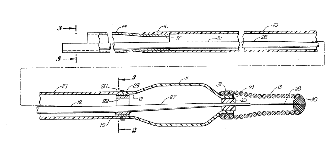
FIG. 1 is an elevational view, partially in
section, of a dilatation catheter which embodies features of
the invention;
FIG. 2 is a transverse cross-sectional view taken
along the lines 2-2 shown in FIG. l;
?, ~
FIG. 3 is a transverse cross-sectional view taken
along the lines 3-3 shown in FIG. l; and
FIG. 4 is an elevational view, partially in section
of a Touhy Borst adapter mounted on the proximal end of the
catheter shown in FIG. 1.
DETAILED DESCRIPTION OF TH~ INVENTION
FIGS. 1-3 illustrate a dilatation catheter which
embodies features of the invention. Generally, the catheter
includes a main tubular member 10, an inflatable balloon 11
on the distal portion of the tubular member, an inner guide
member 12 which extends through the tubular member and the
interior of the balloon, and a helical coil 13 which is
disposed about a portion of the guide member which extends out
the distal end of the balloon.
The main tubular member has a relatively stiff
proximal portion 14, which is preferably formed of stainless
steel hypotubing, and a longitudinally flexible distal portion
15, which is preferably formed of a high-strength polymeric
plastic, such as a polyester. The proximal end 16 of the
distal portion 15 is fitted over and secured to the tapered
distal end 17 of the proximal portion 14. The interfitting
ends 16 and 17 may be bonded by an adhesive or other suitable
means.
The distal extremity 20 of the distal portion 15
is bonded by an adhesive 21 or other suitable means to a
short, diametrically rigid cylindrical member 22, preferably
stainless steel hypotubing, which partially fits therein.
The proximal skirt 23 of the balloon 11 is bonded to the
distal portion of the cylindrical member 22. The distal skirt
24 of the balloon 11 is bonded by adhesive 25 to the guide
member 12 which extends therethrough.
2 ~ t_1 ~
The guide member 12 generally has a main wire
section 26 of constant diameter, one or more tapered portions
27, and a flattened distal section 28. Rounded plug 30 is
formed on the distal tip of flattened section 28. The
5 proximal end of the main wire section 26 is secured to the
interior of the proximal portion 14 by suitable means, such
as soldering, brazing, or welding. The guide member 12 is
also bonded at an intermediate location, such as the tapered
section 27 to the interior of the cylindrical member 22, by
means such as soldering, brazing or welding. Soldering with
gold is preferred.
Helical coil 13, preferably tapered as shown in
FIG. 1 to facilitate advancement of the catheter through
tortuous anatomy, is bonded to the proximal end thereof to
the exterior of the distal skirt 24 of the balloon 11 by a
suitable adhesive 31 and the distal end is bonded to the
rounded plug by welding or the like. Helical coil 13 is
preferably formed at least in part of a radiopaque material,
such as platinum, palladium, molybdenum, tungsten, rhenium,
and alloys thereof.
As shown in FIG. 4, the proximal end of the tubular
member 10 is secured to a Touhy Borst adapter 32 which has a
body 33, preferably formed of polyvinyl chloride, a cap 34,
preferably formed of nylon, and an inner seal member 35,
preferably formed of silicone. The cap 34 has a female Luer
connection 36 which is adapted to receive an inflation device
(not shown) such as the IndeflatorTM inflation device sold by
Advanced Cardiovascular Systems, Inc., the applicant herein.
See U. S. Patent 4,439,185 and U. S. Patent 4,743,230.
The proximal portion 14 of the main tubular member
10 typically has a length of about 50 cm, an outer diameter
of about 0.032 inch (0.82 mm) and an inner diameter of about
0.023 inch (0.50 mm). The distal end thereof is ground to an
J~ ~ ~
outer diameter of about 0.027 inch (0.69 mm) to fit within the
proximal end of the distal portion 15 of the tubular member
10. The distal portion 15 is typically about 95 cm in length
and has an outer diameter of about 0.034 inch 0.86 mm) and an
inner diameter of about 0.028 inch (0.71 mm). The short
cylindrical member 22 has a length of about 5 mm, an outer
diameter of about 0.027 inch (0.69 mm) and an inner diameter
of about 0.023 inch (0.58 mm). The main wire section 26 of
the guide member 12 is about 125 cm in length and has an outer
diameter of about 0.012 inch (0.30 mm). The tapered section
27 is about 12 cm in length with the flattened distal end
thereof being about 2 cm long and about 0.002 inch (0.05 mm)
thick. The coil 13 tapers from an outer diameter of about
0.034 inch (0.86 mm) at the proximal end to 0.018 inch (0.46
mm) at the plug 30. The balloon 11 including the skirts 23
and 24 is about 3 cm long and can have various inflated
diameters as is well known in the art, typically ranging from
about 1 to about 5 mm.
The proximal portion 14, the short cylindrical
section 22 and the guide member 12 generally can be made from
stainless steel in a conventional manner, although all or
portions thereof mav b~ made from other materials such as
nitinol, which is an alloy of nickel and titanium having super
elastic properties.
The distal portion 15 of the main tubular member
10 is preferably formed of a poly~ster elastomer preferably
a block copolymer of polybutylene terephthalate such as
Hytrel~M 7246. Hytrel is a registered trademark of DuPont.
The balloon is preferably formed of an inelastic
thermoplastiG material, such as polyethylene and polyethylene
terephthalate, in a conventional manner well known in the art
to generate a biaxial orientation. Polyvinyl chloride may
also be used.
5` !~ ~ ~
While the present invention is described herein
with reference to an embodiment which is particularly adapted
for use in peripheral arteries, various modifications can be
made without departing from the scope thereof.