Note: Descriptions are shown in the official language in which they were submitted.
- 20167~.8
47982-59
Canada
TUNNEL FOR TREATING AN ELEMENT IN A GAS
ENVIRONMENT INCLUDING A GAS GENERATOR
The present invention relates to treating an element
with a reducing gas soldering, and more specifically, to
soldering in the presence of a reducing gas in an enclosed
zone.
Soldering of printed wiring boards and other similar
types of elements, without the application of flux, has a
number of advantages including avoiding the step of applying
: flux prior to soldering and eliminating the necessity of
cleanlng the flux deposits from the solder joints after
soldering. Fluxless soldering may be carried out in an inert
~15 gas atmosphere generally with a reducing agent or other
: solder additions which may perform the same function as flux,
that is to prevent oxidation of the solder, and provide clean
solder connections. In the case of solder bath, or solder
wave type of soldering, the absence of flux reduces flux
deposits in the solder and when liquid solder is maintained
in an inert atmosphere, there is a reduction of solder oxides
known as dross that form on the solder surface.
Co-pending application filed concurrently herewith,
20~6~8
entitled Shield Ga~ Wave Soldering, Serial No.
discloses soldering in a shield gas atmosphere.
In one embodiment, soldering is achieved by conveying an
element so that it is contacted by a solder wave. In another
embodiment, reflow soldering is used wherein solder paste or
solder plating is first applied to the metallic components to
be soldered and the element is then heated so that the solder
melts to liquid solder which flows to form the solder joint. -
Most solder paste used for reflow soldering includes flux.
However, if reflow soldering occurs in an inert atmosphere
with or without a reducing agent, then reduction of the
quantity of flux or modification of the chemical nature of
the flux in the solder paste can be achieved.
Co-pending application concurrently filed herewith
entitled Tunnel for Fluxless Soldering, Serial No.
discloses soldering of elements, such as printed wiring
boards, in a non-explosive gas atmosphere which substantially
excludes oxygen.
Soldering in an enclosed zone is also disclosed in co-
pending application filed concurrently herewith, entitled GasCurtain Additives Zoned Tunnel for Soldering. In this
application an apparatus is disclosed for soldering an
element in an enclosed zone containing a gas atmosphere. The
enclosed zone has an entry and an exit and at least one fluid
barrier curtain at the entry and at least one fluid barrier
~ ` , .
t~
20167~.~
curtain at the exit. The conveyor conveys an element through
the fluid barrier, and in one embodiment an additive aid
soldering is added to the fluid in the curtain at the entry.
In another embodiment a plurality of zones are supplied in
line with a conveyor to convey elementæ through the zones.
Fluid barrier curtains are provided between the zones.
It is known to conduct wave soldering in a reducing gas
atmosphere, and Bertiger in U.S. patent 4,538,757 discloses
wave soldering in an enclosure containing nitrogen and
hydrogen. Oxygen is excluded from the enclosure to avoid an
initial fluxing step. It is disclosed in this patent that a
high proportion of nitrogen in the mixture reduces the risk
of an explosive mixture.
Hydrogen is often used for high temperature brazing
processes and the like, and although some may consider it is
not beneficial for normal soldering temperatures, i.e. 300 -
400-C, the literature indicates that it is a preferred
reducing gas for soldering copper circuit boards. However,
it is known that hydrogen is an explosive gas and therefore
the use of hydrogen in an explosive mixture presents certain
hazards.
It is an aim of the present invention to treat elements
in an enclosed zone with a reducing gas. The treatment may
be soldering, curing, drying or other type of treatment
requiring the presence of a reducing gas.
- 3 -
20167~ 8
It is another aim of the present invention to provide a
safe soldering apparatus that utilizes an explosive gas such
as hydrogen. This is achieved by combining an enclosure with
gas curtains at the entry and exit, a gas generator that `;
produces only the quantity of gas necessary for the
enclosure, there being no shortage of gas necessary and there
being substantially instant cut off of gas supply. This
avoids the necessity of storage containers of hydrogen, which
even if located far from the apparatus have feed lines that
risk being damaged, or can leak. Furthermore, burn-off of
excess gas occurs at the gas curtains at both the entry and
the exit. Thus a safe soldering apparatus where a high
percentage of an explosive gas such as hydrogen can be used
for high efficiency soldering.
It has now been found that if one provides an enclosed
zone wherein there are two fluid barrier curtains at the
entry and the exit, one is able to provide the fluid barrier
curtains with an inert gas to contain the gas environment
within the enclosed zone. Then one can supply a reducing gas
which may be an explosive gas such as hydrogen to the
enclosed zone and burn off any excess reducing gas at the
fluid barrier curtain. This permits a far higher
concentration of hydrogen within the enclosed zone, resulting
in a greater reducing action for treatment such as soldering.
Furthermore, by providing a hydrogen ga~ generator to feed
the enclosed zone, one does not have to store hydrogen, and
-- 4 --
, . .:
.. ~ .
` A . ~
.~, ' ' ` , .
;~016~ ~
the supply can be cut off almost instantaneowsly by turning
off the generator.
The present invention provides a process for treating an
element with a reducing gas, comprising the steps of
conveying the element through an entry into an enclosed zone,
the entry containing at least one fluid barrier curtain
wherein the fluid is an inert gas, filling the enclosed zone
with the reducing gas; heating the element in the zone;
conveying the element from the enclosed zone through an exit
containing at least one exit fluid barrier curtain, wherein
the fluid is an inert gas, and burning off excess reducing
gas at the entry and exit fluid barrier curtains.
The present invention also provides an apparatus for
treating an element with a reducing gas comprising an
lS enclosed zone having an entry and an exit; a conveyor means
adapted to convey an element in a conveyor path through the
enclosed zone from the entry to the exit; at least one entry
fluid barrier curtain in the entry, having a burn-off for
combustible gas above the curtain; heating means to heat the
enclosed zone; at least one exit fluid barrier curtain in the
exit, having a burn-off for combustible gas above the
curtain; inert gas supply for the entry fluid barrier curtain
and the exit fluid barrier curtain, and reducing gas supply `::
for feeding into the enclosed zone. In a further embodiment,
the reducing gas supply is a hydrogen generator with no gas :-
storage and with a substantially instantaneous gas cut off. ~ ;;
- 5 -
,'''~' '.' `.`''
2016~ ~
In drawings which illustrate embodiments of the present
invention,
Figure 1 is a schematic side view illustrating one ~ -
embodiment of an enclosed zone for treating an element with a
reducing gas.
Figure 2 is a schematic side view illustrating
another embodiment of an enclosed zone for wave soldering.
Figure 3 is a schematic side view illustrating a
further embodiment of an enclosed zone for wave soldering.
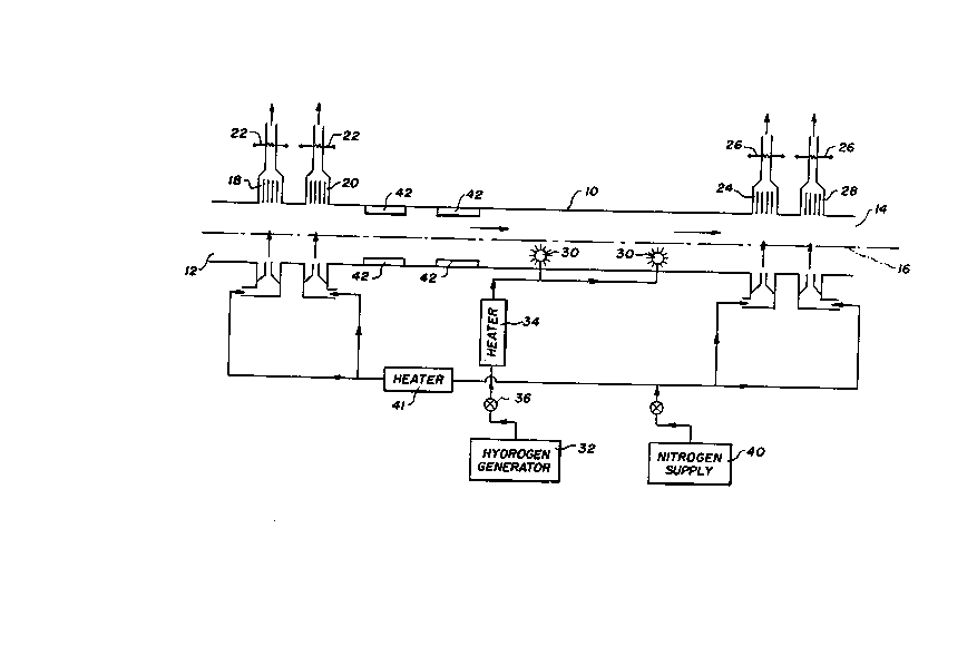
Figure 1 illustrates an enclosure 10 which has an entry
12 and an exit 14. A conveyor path 16 extends from the entry
12 to the exit 14 passing through the enclosed zone 10
suitable for conveylng elements into and out of the zone 10.
The elements, which are circuit boards or other similar types
~ .
~lS of~wirlng boards and the like, are heated and treated, for
example soldered within the zone 10. In another embodiment
the elements may be those that require curing, drying or
otherwise processed in a gas atmosphere.
Two fluid barrier curtains are provided at both the
entry 12 and the exit 14. The fluid barrier curtains are
preferably tho~e of the type disclosed in U.S. patent
4,696,226. The first entry fluid barrier curtain 18 and the
-- 6 --
. ., :
201~,7~ ~
,
second entry fluid barrier curtain 20 are both supplied with
an inert gas, preferably nitrogen, to provide a barrier for
sealing the enclosed zone 10. Above the first and second
entry curtains 18 and 20 are burn off exits each with a burn
off device 22, such as an electrical element, for burning off
hydrogen or other combustible reducing gas that exits from
the curtains 18 and 20. First and second exit fluid barrier
curtains 24 and 28 are provided with an inert gas such as
nitrogen so that the reducing gas can not escape out of the
enclosed zone 10. Burn off exits above the first and second
exit curtains 24 and 28, each have a burn off device 26, such
as an electrical element, to ensure all combustible gas is
burnt off. Whereas an electrical element 26 is illustrated
herein, a pilot light may be provided, gas or oil operated,
for the burn off devices 22 and 26.
Because inert gas curtains are provided on both the
entry and exit to the enclosed zone 10, hydrogen, which may
be premixed up to the highest concentrations obtainable may
be supplied to the zone through entry ports 30 within the
enclo~ure. Any excess hydrogen from within the enclosure
exits through the curtains 18, 20, 24 and 28, and is burnt
off by the burn off devices 22 and 26. Thus no combustible
gas escapes into the atmosphere.
A hydrogen generator 32 is preferably provided for
supplying hydrogen to the enclosed zone 10. The hydrogen
generator is preferably a mul'iple cell electxolysis
- 7 -
- 20167~
generator for producing both hydrogen and oxygen in a perfect
2 to 1 ratio from water. One example of such a generator is
sold by SPIRIG of Switzerland under the trade mark SPIRFLAME.
The generator uses a modest amount of electric energy and
different capacities of generator are provided for different
uses. The hydrogen generator has the advantage of not
storing any hydrogen whatsoever, and being able to easily
control the quantity of hydrogen made available to the
enclosed zone 10. By turning off the generator, in other
words stopping the electrical power to the generator, the
hydrogen flow immediately stops. No hydrogen remains in the
generator so there is no hazardous condition. The gas
remaining in the enclosure 10 is burnt off by the burn off
devices 22 and 26.
In another embodiment a mixture of gases, one of which
is a reducing gas, may be prepared in a desired concentration
for filling the enclosed zone 10. The ratio of hydrogen and
inert gas such as nitrogen, ozone, argon and the like may be
premixed to the desired concentration. A generator for
nitrogen may be supplied, or alternatively, nitrogen may be
supplied from bottles.
A heater 34 is illustrated to heat the hydrogen from the
hydrogen generator 30, or hydrogen mixture feeding both the
entry ports 30 to the enclosed zone 30. A control valve 36
i~ shown for controlling hydrogen flow. In one embodiment
another gas may be premixed with hydrogen, prior to entering
: . .
.
. . ,: ~, .
,~
20167~ ~
the enclosed zone 30. A mixer and valving system is not
illustrated, but would be apparent to one skilled in the art.
The nitrogen supply 40 feeds the entry and exit fluid
barrier curtains 18 and 28. In one embodiment, a nitrogen
heater 41 heats the nitrogen to the two entry curtains 18 and
20. The heated nitrogen assists in heating elements entering
the enclosure 10. Other heaters 42 positioned below the
conveyor path 16 and in some configurations above and below
the conveyor path 16 in the enclosed zone 10 also assist in
heating the elements. By providing a plurality of heaters 42
a heating profile can be applied to the elements to suit the
required treatment conditions, such as soldering, curing,
drying and the like.
A single linear conveyor may be provided to convey
elements along the conveyor path 16 or more than one conveyor `~ ;
can do the same function. The conveyor may support elements
on a series of fingers from one or more side chains, or in
another embodiment, the elements are supported on pallets or -
on an adjustable width conveyor. A flat mesh conveyor not
affected by temperature may also be used.
Soldering may occur in a number of ways. In one
embodiment reflow soldering occurs, wherein a solder paste or
preplated contacts are preheated and solder melts and flows
to form the solder joint. In one embodiment the solder cools
prior to the element coming in contact with the air so that
g
. :~. ~: . : :
::: .~::
:."' '~:
....... . .
20167~ ~
oxidizing of the liquid solder surface is minimized or
eliminated.
In another embodiment as illustrated in Figure 2 a
solder wave 50 is located in the enclosed zone 10. The
S solder wave 50 is positioned above a solder pot 52 and has a
vibrator 54 to provide a vibration to the solder wave. One
embodiment of a vibratory wave soldering is shown in U.S.
patent 4,684,065. The solder wave 50 projects upwards so
that elements passing in the conveyor path 16 contacts the
solder wave. In the embodiment shown in Figure 2, the second
entry curtain 20 and first exit curtain 24 are fed with
hydrogen or a mixture of hydrogen with nitrogen rather than
nitrogen alone. The hydrogen or the mixture of hydrogen and
nitrogen is not heated in the embodiment shown, although if a
heat profile is desired for the elements, then hydrogen or
hydrogen mixture is fed to the second entry curtain 20 may be `-
heated.
Figure 3 shows a further embodiment wherein only one
entry fluid barrier curtain 18 and one exit fluid barrier
20 curtain 28 are provided. Both curtains are fed from a
nitrogen supply 40 and have burn off devices 22 and 26 in the
form of electrical elements at burn off exits. There is
provided a solder wave 50 positioned above a solder pot 52,
but no vibrator is shown.
-- 10 --
_.. _.. ,.......... . ~- .
~ : .
~:
.
.
- 20167~.~
In one embodiment the nitrogen supply to the second exit
curtain 28 is cool or is cooled so that the elements leaving
the enclosure 10 are cooled and the solder solidified when
the element passes the second exit curtain 28.
Whereas heaters 42 are shown in both Figures 1, 2 and 3,
they are not always needed, and may be omitted. The heat is
then provided by heating the gas before entering the
enclosure.
Variouæ changes may be made to the embodiment shown
herein without departing from the scope of the present
invention which is limited only by the following claims.
'~'~ '.,,'~'''''.
'~ '' ' ~ ''''
~''~''""~"`
~,;
,. . .
-- 1 1 --