Note: Descriptions are shown in the official language in which they were submitted.
i2~3l6~
1 LID DlSPENSER FOR AN AUTOMATED ~RINKMAKER SYSTEM
The present invention relates generally to a lid
dispenser for an automated drinkmaker system designed to
accept an input order for drinks, as at a East ~ood
restaurant, and to complete and deliver the inished drink
order in lidded cups to an output station in a completely
automated fashion.
More particularly, the subject invention relates
to a lid dispenser for an automated drinkmaker system
designed to accept an input order, as from a cash register,
and deliver the drink order for different drink sizes and
flavors, with or without ice, completely finished in lidded
containers, if desired, to an output station. The automated
drinkmaker system is designed for labor-free processing of
drink orders in environments such as ~uick service or fast
Eood establishments.
Credle U.S. Patent 4,319,441 is of interest to the
present invention by disclosing an automated post-mix drink
dispensing system in which a cup dis;penser dispenses a cup,
into which the ingredients of a soft drink and ice are
introduced. An automatic lid dispenser delivers a lid to
the cup which is applied thereto by a lid applicator, and
the lid is then marked for a designated flavor. The cup is
processed through a complete cycle by a cup indexer which
consists of upper and lower arms with pockets at each end
which hold a cup and move it from one station to the next.
The pockets are adjustable for varying cup sizesO The cup
indexer rotates 180, and then stops with one set of pockets
3 at a fill station or introducing the beverage mix and ice
into a cup, and the opposite set of pockets at the lid
applicator station for lidding of a cup. A cup ejector is
f~
provi~ed which consists of upper and lower arms which
contact a cup a~ter a lid has been applied thereto and
l remove it from the pockets of the cup indexer. The cup
ejector moves through a 135 arc to eject the cup, and then
reverses direction to return to its original position. The
Credle post-drink dispensing system is not as fully
automated or as comprehensive as the present invention, and
can process only two different drinks at a time, as compared
with up to seven different drinks pursuant to the subject
invention. Moreover the Credle system does not have the
capability of interfacing with an ice dispensing system, and
is not fully automated so as to interface directly with a
cash register to process an order entered therein.
The Credle system also does not have the capacity
to store large ~uantities of lids, as offered by the lid
carousel of the present invention. The Credle patent
discloses a lid dispensing system in which lids are stacked
vertically in a lid dispenser which comprises pivotally
mounted support fingers and pivotally mounted gripper
fingers. The gripper fingers are provided with rubber
gripper pads. When the lid dispenser receives a signal to
dispense a lid, four gripper fingers engage the bottom four
lids, excluding the bottommost lid and the gripper fingers
support the entire stack of lids. The four support fingers
then retract and allow the bottommost lid to fall from the
stack. After the bottom lid has been dispensed, the support
fingers return to their original position and the gripper
fingers retract, thus allowing the entire stack to move down
and to be supportPd by the support fingers. The cycle is
then repeated when another lid is needed. Accordingly, the
Credle lid dispenser is substantially different from that of
3 the present invention, and does not utilize a linearly
translating and reciprocating lid shuttle through which lids
are separated and applied in a two cycle process, as in the
_3~
present invention. Moreover, Credle does not disclose an
automatic lid applicator which applies the separated lids to
1 containers in an automated fashion.
The present invention relates to a lid dispensing
and application arrangement for separating lids from a stack
of lids and applying the separated lids onto cups,
comprising a lid dispenser supporting a stack of lids to be
dispensed; and a lid shuttle positioned near the bottom of
the lid dispenser and supported for substantially linear
translating and reciprocating movement between retracted and
extended positions relative to the lid dispenser, said lid
shuttle supporting a lid engaging member designed to engage
a first bottommost lid of the stack of lids and to retain
the first bottommost lid in a first intermediate position in
the lid shuttle while the lid shuttle is moved in
translation to said e~tended position, the lid shuttle then
being moved in translation to said retracted position during
which the first lid is moved in translation within the lid
shuttle to a second loaded position therein beneath a lid
applicator supported by the lid shuttle, the lid shuttle
then being moved to said extended position during which the
irst lid remains in the second loaded position while the
lid engaging member simultaneously engages a second
botto~nost lid of the lid stack and retains the second lid
in said ~irst intermediate position in the lid shuttle, the
lid shuttle then being moved in translation to said
retracted position during which said lid applicator presses
and applies the first lid onto a cup beneath said second
loaded position and the second lid is moved in trarlslation
within the lid shuttle to said second loaded position, and
wherein the cycle is repeated for subsequent lids duxing
3 linear translating and reciprocating movements o~ the lid
shuttle.
The automated drinkmaker machine incorporates
therein a rotatable carousel type of drink transporter which
has a plurality of circularly spaced cup holders thereon.
The drink transporter can carry each drink as it is being
l prepared to and from four circularly spaced stations, cup
dispensing, ice dispensing, soda dispensing, and lid
application and marking. The transporter is a carousel
design that allows a cup to be dispensed at one station
while another cup is being filled with ice at a second
station, and yet another is being filled with soda at a
third station, etc. The use of carousels is extended to
both the cup dispensing station and the lid dispensing
station. The system is designed to interface with any
co~mercially available, portioning ice dispenser, and also
to interface directly with a cash register system to enable
a cashier to directly input a customer order. At an output
station, the cup is raised from the carousel by a linear
transporter (elevator) which carries the cup up and down
through a lidding and marking operation, after which the
completed drink is transferred to an output conveyor and
station.
The rotatable carousel drink transporter carries
each cup in a cup holder supporting the cup below its rim.
One advantage of this design approach is that there is a
greater immunity from contamination of the system by drink
spills, from other drinks which have been processed, as
drink spills can fall onto a drain area therebelow and not
interfere with continued operation of the system.
The automated drinkmaker system can incorporate
therein a lesser or greater number of processing stations or
cup holders. For instance, drink dispensing could be
separated into one or more syrup dispensing stations and a
separate carbonated water dispensing station. Moreover the
3 order of dispensing the drink components, including the
syrup, the carbonated water and the ice, could be varied in
different embodiments.
_5~
The automated drinkmaker machine ma~ be designed
to deliver completed drinks at a rate of ten drinks per
1 minute, taking fifteen seconds for the first drink and five
seconds for each additional drink. Vp to twenty drinks can
be accumulated on the machinels output conveyor at a
completed drink storage area, which can, for example, be
grouped as five orders with four drinks per order, although
the output conveyor could be expanded or contracted to hold
a greater or lesser number of finished drinks. The machine
is designed to operate with three cup sizes, normal 16 ounce
and 22 ounce sizes, and also possibly a 32 ounce promotional
plastic cup, with a cup storage of seven hundred cups.
Although, a different number of different size cups could be
implemented in alternative embodiments. The 16 and 22 ounce
cups have the same upper cup diameter, and the drink
transporter has alternately sized cup holders thereon, one
size Eor the 16 and 22 ounce cups and a second size for the
32 ounce promotional cups. Lids can be applied to the 16
and 22 ounce cups from a lid storage of 650 lids. The lids
can be marked to identify drinks by three categories diet,
tea or other.
In accordance with the teachings herein, the
present invention provides a lid dispensing and applicator
arrangement for such an automated drinkmaker. The lidding
arrangement is completely automated, ~nd separates lids from
a stack of lids and applies the separated lids onto cups.
In the arrangement, a lid dispenser supports a stack of lids
to be dispensed, and a lid shuttle is positioned near the
bottom of the lid dispenser, and is supporte~ for
substantially linear translating and reciprocating movement
between retracted and extended positions. The lid shuttle
3 supports a lid engaging member designed to engage a first
bottommost lid of the stack of lids, and to retain the first
bottommost lid in a first intermediate position in the lid
-6~
shuttle while the lid shuttle is moved in translation to its
extended position. The lid shuttle is then moved in
1 translation to the retracted position, during which the
first lid is moved within the lid shuttle to a second,
loa~ed position therein beneath a lid applicator supported
by the lid shuttle. The lid shuttle is then moved to its
extended position, during which the first lid remains in the
second loaded position while the lid engaging member
simultaneously engages a second bottommost lid of the lid
stack and retains the second lid in the first intermediate
position in the lid shuttle. The lid shuttle is then moved
in translation to its retracted position, during which the
lid applicator presses and applies the first lid onto a cup
positioned therebeneath, and the second lid is moved within
the lid shuttle to the second loaded position. The cycle is
then repeated for subsequent lids during linear translating
and reciprocating movements of the lid shuttle.
In accordance with further details of a preerred
embodiment, the lid dispensing and applicator arrangement
includes a lid carousel having a plurality of stacks of lids
supported therein which is positioned above the lid
dispenser for periodically refilling the lid dispenser with
lids. The lid carousel has a stationary flat base with a
circular aperture therein positioned above the lid
dispenser. The rotatable carousel rotates the plurality of
stacks over the stationary flat base to position a stack of
lids over the circular aperture for refilling of the lid
dispenser. The rotatable carousel is driven in rotation by
a pulse stepper motor, driven by pulses issued by a
controller which controls operation of the rotatable
carousel. The lid shuttle is moved in linear and
3 translational movement along a pair of slider bars by a
screw drive driven by a pulse stepper motor, controlled by
pulses issued by the system controller which controls
operation of the lid shuttle. The lid applicator is angled
relative to the translational movement of the lid shuttle.
1 The lid engaging member is formed by an upwardly extending
hook which is spring biased upwardly against the bottommost
lid in the lid dispenser. The lid dispenser comprises a
pair of spaced bottom support members supporting a stack of
lids, and the hook is moved in translation in the space
between the pair of spaced bottom support membersO The lid
dispenser also supports a spring biased gate member which
allows the bottommost lid to pass therethrough as the lid
shuttle moves to its extended position., The gate member
remains closed as the lid shuttle moves to its retracted
position, and presses against and moves a lid from the first
intermediate position to the second loaded position within
the lid shuttle. Moreover, a stationary block is positioned
adjacent to the gate member to block the secondmost bottom
lid as the bottommost lid is being moved through the gate
member. The lid applicator is constructed to provide a
constant force downwardly to press and apply a lid onto a
cup, regardless of different deflected positions of the lid
applicator caused by different heights of cups due to
differences in tolerances on the heights of cups.
The present invention for a lid ~ispenser for an
automated drinkmaker system may be more readily understood
by one s~illed in the art with reference being had to the
following detailed description of several pre~erred ~, ,
embodiments thereof, taken in conjunction with the
accompanying drawings wherein like elements are designated
by identical reference numerals throughout the several
views, and in which:
Figure 1 is a front perspective view, partially
3 broken away, of an exemplary embodiment of an automated
drinkmaker machine;
Figure 2 is a schematic illustration of the drink
trans~orter carousel, shown carrying three cups~ and the
elevator assemb~y which carries a cup through lid
application and marking operations;
1 Figure 3 is a top plan schematic view of the
automated drinkmaker machine, illustrating the relative
positions of a cup carousel, a lid carousel, and an output
conveyor and finished drink storage area;
Figure 4 is a top plan schematic view of the
output conveyor and finished drink storage area and a pusher
arm for moving a finished drink -from an output station of
the automated drinkmaker to the front of the output
conveyor;
Figure 5 illustrates a front elevational view of
the output conveyor of Figure 4, and also shows the customer
numbered order displays;
Figure 6 is a top planar partially sectional view
of the drink transporter carousel drive mechanism and
positional sensor mechanism, and also illustrates the
elevator platform and its support and drive mechanisms;
Figure 7 is a partially sectional elevational view
o~ ~he carousel drive mechanism and the positional sensor
mechanism;
Figure 8 is a side elevational view of the cup
carousel and cup dispensing subassembly;
Figure 9 illustrates schematically the lid
carousel and the lid dispenser and applicator forming the
subject matter of the present invention;
Figure 10 is a side elevational view of one pair
of separati~g ~ingers, through which a cup is successively
moved as it is separated from a cup stack;
Figures 11 through 14 illustrate respectively four
successive steps of separating and dispensing a cup from a
3 stac~ of cups through a set of oppositely disposed
separation fingers;
Figures 15 and 16 illustrate two successive steps
--9 ~--
2~
o dispensing a lid Erom a column o~ stacked lids and
applyiny it onto a cup;
l Figure 17 is a schematic illustration of drink
order processing by the processor of the automated
drinkmaker;
Figure 18 illustrates a side schematic view of the
cup dispenser actuator mechanism;
Figure 19 illustrates a side elevational view of
the lid dispenser of the present invention with the lid
shuttle being in a retracted position, ready to pull a lid
from the bottom of a lid stack;
Figure 20 is a top plan view of the lid dispenser
in the retracted position of Figure 19;
Figure 21 illustrates a side elevational view of
the lid dispenser with the lid shuttle being in an expanded
position, ready to apply a lid onto a cup as it moves to a
retracted position; and
Figure 22 is a top plan view of the lid dispenser
in the expanded position of Figure 21.
Referring to the drawings in detail and in
particular to Figures 1-3, a disclosed automated drinkmaker
10 is illustrated positioned on top of a counter 12 and in
front of a commercially available portioning ice dispenser
14, and includes a controller cabinet lS for housing the
contrQller for the automated drinkmaker system. The
automated drinkmaker is described and claimed in detail in Can.
patent application (docket 7300), and is designed around a
carousel type of drink or cup transporter 16, Figures 1 and
2, which is designed to allow for parallel processing of up
to seven drinks.
The drink transporter 16 moves a cup in a circular
3 path intermittently through four drink preparation stations.
The carousel drink transporter 16 carries each cup
intermittently in a circular path to each of four processing
stations, cup dispensing 17, ice dispensing 18, soda
dispensing 20, and finally to an output station 22. At the
output station 22, the cup is ~ransferred to a linear
l elevator transporter 24 which carries the cup up and down
through a lidding and mar~ing procedure and brings it to
rest at a proper height so that the completed drink can be
transferred by a pusher or sweeper arm 26 to an output
conveyor 28. Order displays 29, Figures 1 and 5, are
provided adjacent to the output conveyor 28 to display a
drink order number in association with each completed drink
order. The order number is indexed to the right with
movement of the output conveyor 28 as additional finished
drink orders are deposited onto the output conveyor 28.
The automated drinkmaker 10 also includes a cup
carousel 34 for supplying at least two, and possibly three,
different size cups to a cup separator and dispenser which
dispenses the proper size cup onto a cup holder of the drink
transporter 16. Moreover, a lid carousel 56 holds at least
four stacks of lids which are supplied to the lid dispenser
and applicator of the present invention, which separates
lids from a lid stack and applies them on top of a finished
drink cup. A display 19 is also provided to display various
messages and data to operating perso~nel, such as to
resupply lids or cups, or to check a particular area fo~ a
problem such as a jam, or to display entered orders. Entry
buttons are also available in association ~ith the display
to enter orders, or indicate that specific actions, such as
lids resupplied, have been taken.
Figures 6 and 7 illustrate details o~ the carousel
drink transporter 16 drive system and also the elevator
plat~orm 24 drive system. Referring thereto, the drink
transporter carousel 16 is mounted on a ~ertical output
3 shaft 21. A stepping motor 23 drives a pulley 25 secured to
the bottom of the vertical output shaft by a belt drive
extending therebetween. An encoder plate 27 is secured to
the vertical output shaft 21 ~or rotation therewith, and
includes eight different size (either large or small) light
l transmitting notches 29 therearound which are sensed by an
encoder detector 31 placed adjacent ~o the encoder plate 27.
The cup transporter is driven by the stepping motor 23 which
is issued a number (e.g. 800) of pulses necessary to
accomplish a required cup transporter, e.g. 90~ rotation,
and the rotation is detected by the encoder detector 31.
The encoder plate sensor signal is checked by the system
controller to determine that the on-off signals are being
received at the proper time (the machine is in
synchronization). If a transporter sync error is detected,
an error message '`CHECK TRANSPORTER" is displayed.
Responsive thereto, the operator is to check the drink
transporter, and signals the processor by pressing a button
that the transporter is clear with no jammed cups. Once
that signal is received, the machine pulses the transporter
stepping motor until one of the small or larger slots,
positioned 45 apart around the encocler disk, passes by the
encoder sensor. The number of pulses required to step the
disk through the slot indicates to the machine processor if
it is a small or large slot. The system knows the quadrant
it was operating in prior to the stall, and thus can
ascertain its position completely, and can resume operation. ;~
Figure 6 illustrates the platform elevator 24
which is driven for vertical elevational movement by a
stepper motor 33 driving a screw drive 35 and also supported
for movement by a vertically extending slider element -
coupling 37. The platform elevator serves the fourth work
station, which is the lidder and marker station, at which
the elevator 24 lifts a drink from the transporter and
3 positions it at the proper height for lidding. The position
of the elevator 24 is first initialized when the machine is
turned on, and the position is then maintained and tracked
~ -12- ~6~
in memory. The elevator is a screw drive 35, driven by the
stepper motor 33, and additionally includes a linear enco~er
1 plate with a notch detected by an associated encoder type of
sensor when the elevator is at -the output conveyor 28
position. Accordingly, when pulse commands are given to
drive the elevator, the system processor also calculates the
time ~hen the encoder sensor should detect a transition, and
looks for the transition at that time. If the transition is
not detected at the calculated time, the machine is out of
synchronization, and the operator is notified to check the
elevator for problems, and indicates by pushing a button
after the elevator is checked and is free to operate. Th~
machine then resynchronizes itself by looking for the
encoder plate notch, and then resumes normal operation.
The position of the elevator is always checked
first ~y the system processor prior to issuing a drive
command to the drink transporter to determine that the
elevator is in a noninterfering down position. The size of
cup delivered by the drink transporter to the elevator is
known. The lid applicator is a known given distance above
the drink trans~orter, and acc~rdingly the processor
determines the vertical drive necessary for the cup size
being lidded to raise the cup to the lid applicator to a
standard lid applicator position for all cup sizes. The lid
applicator is already positioned at its outermost position
with a lid in position to be applied to a cup when the
elevator raises the cup rim to the standard lid applicator `.
position.
The motions for both the elevator 24 and the drink
transporter 16 are programmable, so that cups of varying
proportions can be accommodated~ The drink transporter 16 '~
3 can move either 90 or 45 depending upon the cup size it is
carrying. The elevator 24 has a seven inch stroke, and is
programmed to stop at any point in its travel to accommodate
different cup sizes.
-13-
Two different size cup holders 30, Figure 2, are
incorporated into the drink transporter, and both operate
l in the same manner. One cup holder is sized for carrying
medium (16 ounce~ and large (22 ounce) cups, both of which
have the same upper rim diameter, and the second is sized
for promotional (32 ounce) cups. An important design
feature is that the cup holders 30 are passive devices, as
illustrated in Figures 1 and 2, that hold the cup throughout
the drink preparation cycle and allow removal of the cup by
the elevator 24 at the output station 22. The design of the
cup holder relies upon the tapered shape of a cup. The
opening of the cup holder is sized such that the cup can
slide out of the cup holder when the cup is raised by the
~levator 24, but is securely held therein when the cup is
carried just below its rim.
The cup dispenser subassembl~ 17 is described and
claimed in detail in Can. patent application (docket 7301),
is illustrated in Figure 8, and can dispense cups ~rom any
one of six stacks 32 held in a cup carousel 34, with only
two actuators. A first actuator, a stepping motor, is a
part of a cup carousel drive 36 which is used to rotate the
proper stack into a cup dispensing position above the cup
dispensing station 17 and the second actuator 36, a stepping
motor, is used to dispense the cup. A unique design feature
of the cup dispenser is that it moves a stack o~ cups
through a small swinging motion ~3 ~3.6) to dispense a cup,
which is distinctly dif~erent ~rom other prior art
dispensers in that the cup stack moves through opposed
separating members rather than the separating member(s)
moving between adjacent cups. This design strategy allows
the use of a simple pivot and allows a single actuator to
3 provide all the dispensing motion. The nature o~ the design
enables a minimization o~ the package size and results in a
more reliable system having fewer moving parts.
6~c
Rach cup stack 32 is pivotally mounted about a
simple pin pivot 40 on the cup carousel 34, such that each
l stack 32 is rotatable to swing through an arc about pivot
40, towards and away from the central axis of the cup
carousel. Each stack 32 is also spring biased outwardly by
a spring 42, which can be a simple flexed spring extending
in compression between opposed stacks 32 to a stopped normal
outward position, as shown in Figure 8. The cup carousel
can be rotated with the cup stacks positioned in their
normal outward positions.
The cup dispenser suhassembly is formed of three
main elements, a cup carousel drive 36, a cup dispensing
actuator 38, and a cup carousel 34. The cup dispenser
subassembly is designed to store and dispense a sufficient
~uantity of cups to take a high volume restaurant through a
peak demand period without requiring a refi.11. As currently
designed in the illustrated embodiment, the cup carousel can
store 700 cups (450 medium 16 ounce, 200 large 22 ounce, and
50 jumbo 32 ounce).
The cup carousel drive 36 of the cup dispensing
subsystem serves two functions, first it positions a proper
size cup tower over a cup holder at the cup dispensing
station 17 on the carousel drink tra~sporter, and secondly
it serves as the structural support ~or the cup carousel 34.
The cup carousel assembly includes a s~epping motor, a
drivetrain, an encoder disc and sensor, an output shaft, and
a support ~rame. A unique feature o~ this assembly is that
it uses a simple, low cost mechanism and encoder to position ::
the cup tower. This design enables the system to find the
correct cup tower regardless of the number of times power is -;
turned of~ and on. In this arrangement the cup carousel 34
3 is rotated, under command of the controller, by the stepping
motor carousel drive 36. The drive arrangement 36 can be a
relatively simple arrangement in which a stepping motor
drives a belt attached to a pulley which rotates the cup
-15
carousel, and the position of the cup carousel is sensed by
a stationary encoder detector mounted relative to an encoder
1 plate which rotates with the cup carousel, similar to that
described hereinabove with respect to the drink transporter
carousel.
Once the proper cup stack 32 holcling the proper
cup size for the drink order being processed is rotated into
the dispensing position, illustrated at the left stack of
Figure 8, the cup dispensing actuator 38 is actuated through
a cup dispensing cycle. The cup dispensing actuator 38, as
illustrated in Figures 8 and 18, is basically a stepping
motor driving a crank arm 3~, which is pivotally attached at
41 to an actuator arm 43 which is mounted at its second end
to a slider bar 44 for linear sliding movement 46 towards
and away from the central axis of the cup carousel. The
second end of the actuator arm 43 includes a contact hook
extension 48 which is positioned behind a contact arm 50
attached to the cup stack 32. With ~his arrangement, when
the stepping motor drives cran~ arm 39 through one full
revolution, contact extension 48 is driven, as at 46,
through one cycle first away from and then towards the
central axis of the cup carousel. This causes the cup stack
to be driven through a pair of opposed cup separating
fingers 52, 54, Figure 1~, as described in greater detail
hereinbelow. The slider bar 44 has an inductive sensor 45
mounted adjacent to its end, and the cup dispenser motor is
pulsed until the inductive sensor 45 detects one complete
cycle, indicated ~y the slider bar being removed from the
inductive sensor, or the system times out, indicating a
stall. An advantage of this design is that the system can
be driven thxough minor stalls and cup jams. The overall
3 subassembly design re~uires that only one cup stack be moved
at a time, while utilizing a single stepping motor for all
of the cup stacks.
-16- 2
The cup carousel assembly consists of six cup
towers 32, the support structure for pivotting those towexs,
l 40, Figure 8, the cup separating members (Eingers) 52, 54,
and the cup tower return springs 42.
The cup separating fingers S2, 54, illustrated in
Figures 10 through 14, have a unique design and utilize a
multiple stage separating method for separating the
bottornmost cup in a stack from the cùp immediately above it.
one set of cup separating fingers 52, 54 is illustrated in
Figure 10, and a second set of mirror image cup separating
fingers is positioned at the bottom of each cup stacX,
positioned apart by the exterior width of a cup just below
the cup rim. The cup separating fingers ~2, 54 are
maintained stationary relative to the cup stack as the cup
stack 32 is rotated through the swinging motion ~ . In the
first two stages of cup separation illustrated in Figures
11, 12 and 13, the cups are drawn back and forth across the
relatively stationary fingers. The curved surfaces of the
cup separating fingers push the cups apart, until there is
sufficient space between the two lowermost cups to enable
the ~ottommost cup to drop onto the CUp supporting fingers
below, Figure 13. The third stage, Figuxe 14, allows the
cup to fall when it is properly positioned over a c~p holder
on the drink transporter.
CUP separation is a two stage procedure that
requires two full cycles, one for each step of the cup
dispensing actuator, to cause a cup to travel through the
finger network. In the first stage, the fingers force
partial separation of the cups~ During the second stage the
cups are further separated and end up in the final staging
area, ready to drop. Once the system has been primed,
3 Figure 13, the bottom CUD iS dispensed very quickly during
the first half stroke of the slider crank rnechanism. So,
while one cup is being dispensed, the next cup immediately
above it is being separated from the stack.
-17~
The two stages of separation advantageously allow
for separation of two cups with less force heing applied to
l the cup rim, thereby reducing the likelihood of damaging the
cup rim and causing a jam. Also, the two stage procedure
permits separation in a small travel distance, allowing for
a compact désign of the cup separating mechanism.
As illustrated in Figure 11, in the first stage oE
separation the bottommost cup is initially supported by the
upper surfaces o~ the opposed upper right fingers of 5~. As
the cup stack swings to the left proceeding from the
position of Figure 11 to that of Figure 12, the bottom
surfaces of the opposed upper left fingers 52 cause a
separation of the lowermost cup such that it falls onto and
is no~ supported by the upper surfaces of the opposed lower
left fingers 52, Figure 12. The cup stack then swings back
to the right, and the lowermost cup is then separated by the
lower surfaces of the opposed upper right fingers 54, and
falls onto and is supported by the opposed upper surfaces of
the lower right fingers 54, Figure 13. As the cup stack
then swings back to the left, the bottom cup is displaced by
the lower surfaces of the opposed lower left fingers 52, and
is displaced off of the opposed upper surfaces of the lower
right fingers to be dispensed and falls into a cup holder in
the dxink transporter carousel.
In the ice dispenser 14 interface, the ice
dispenser is treated as an add~on to the system. The
automated drinkmake~ system is designed with an opening in
the back of the machine to accommodate and allow a chute
~rom an ice dispenser to be inserted into the ice dispensing
- station of the drinkmaker. A connector on the back o~ the
drinkmaker carries input/output signals to the ice dispenser
3 for controlling the portion of ice, and the timing of
dispensing thereof.
A soda dispensing head is mounted a~ove the soda
dispensing station 20 of the automated drinkmaker. The
drink dispenser ~an be a quick pour type of drink dispenser
such as described in U.S. patent application Ser. No.
l 107,403 for Soft Drink Dispenser. Controls within the
drinkmak~r determine the proper flavor to be dispensed and
regulate the portion size. The portion size is calculated
by the system controller, knowing the size cup to be filled
and the flow rate (for each flavor) from the dispensing
head. The calculated value is the time required for a
particular flavor syrup and carbonated water to fill a cup.
The portion control can also be decoupled from the
controller, which allows the drinkmaker system to be
operated in a manual mode. Moreover, the position control
can also handle special drink orders, such as those
requiring no ice, and still fill the cup to the top.
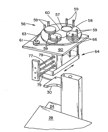
The lidder subassembly, Figures 9, 15, 16, and
19-22, serves three functions, storage of the lids,
separation of the bottommost lid from the rest of the stack,
and the application of the separated lid onto a cup. The
lids are stored in a lid carousel 56 in four stacks, which
are designed to take a high volume restaurant through a peak
demand period without requiring a refill. The lid carousel
comprises a rotatable base plate 58 which has four circular
holes 57 therein to define the positian of the four lid
stacks, each of which is maintained in position by two
vertically extending retaining rods 39 and a central
retaining housing having a substantially square shape
indicated by the base line 60, with the retaining housing
extending upwardly therefrom for the height of the lid
stacks. The rotatable base plate 58 can be rotated under
control of the drinkmaker controller by a stepping motor 61
which drives a belt G3 extending around the rotatable base
3 plate 58. The rotatable base plate 58 of the lid carousel
56 suppoxts the four stacks of lids on a stationary base
- plate 60 over which the lid stacks slide during rotation of
-19-
the lid carousel. The lid dispensing mechanism 64 is
positioned below a circular hole 66 in the base plate 60,
l such that a renewal stack of lids can be rotated and slides
over the base plate 60 until it reaches the circular hole
66, at which rotation is stopped, to allow the renewal lid
stack to fall through the hole 66 into the lid dispensing
mechanism 64. When the lid stack in the lid dispenser 64
falls below a preset level, an optical lid stack depletion
sensor 68, Figs. 15, 16, is mounted below the plate 60
adjacent to the stack of lids in the lid dispenser 64 and
sends a signal to the controller, and the lid carousel is
rotated to deposit more lids into the lid dispenser 64.
The lid carousel subassembly comprlses the lid
carousel tower 56, the drive motor 61, and sensors. In one
designed embodiment, the lid carousel is a 30 inch tower
that can accommodate four stacks of lids. When the lid
dispenser needs lids, as detected by the lid stack depletion
sensor 68, the lid tower is rotated under control of the
system controller, to a position in which a stac~ of lids
can drop through the hole 66 in the bottom plate 60 into the
lid dispenser 6~. The lid carousel is rotated by the
controller to each of four positions i.n which each o~ four
possible stacks of lids is aligned with the hole in the
~o~tom plate in succession to deliver whatever lids are
available. If no lids are transferred to the lid dispenser
and detected by the lid stack depletion sensor 68 after four
attempts, then the operator is notified on display 19 that
the lid carousel is empty and needs to be refilled.
The lid dispenser 64 uses a linear motion, as
illustrated in Figures 15, 16, and 19-22, to pull a lid from ~:
the bottom of a stack and load it into a lid applicator 70,
3 Figure 15. The lid applicator 70 moves in a straight line
over the cup as it applies the lid thereto. At the start of
the lid application procedure, the lid catches on the front
-20- ~ c
edge of the cup, Figure 16. As the applicator is drawn
rearwardly, the lid is pulled out of the applicator and is
1 applied by a lid presser 71 onto the cup. The lid presser
71 maintains a steady downward pressure on the lid as it is
being drawn out of the applicator, causing the lid to snap
onto the cup. The lid applicator 70 is preferably
constructed of a high yield strength alloy which is designed
to apply a predetermined force downwardly upon the lid
regardless of the magnitude of the deflection of the lid
applicator. It should be recogni~ed that cups are delivered
within a given tolerance range as to their height which will
cause more or less deflection of the lid applicator.
The lid dispenser 64 comprises a lid stack support
and ~rame 72 for supporting a stack of lids to ~e dispensed,
a hook 74, a lid shuttle 76, a drive stepping motor, and
drive components. The drive components include a screw
drive 77 driven by the stepping motor, and two spaced slider
bars 79. The lid shuttle 76 is driven linearly along the
slider bars 79 by the stepping motor and screw drive 77, and
incluàes a shuttle frame which includes a pair of spaced
lateral supports for supporting a lid stack therebetween,
and a connecting frame mem~er which mounts the hook with a
spring bias upward and also mounts the lid presser and
applicator 71. The lid stack support 72 accepts lids from
the lid carouse:L and is designed sush that a hook 74 enters -~
through the bottom of the stack and catches on th~ insid~
lip of the the bottommost lid. With the hook engaged on the
lid, the lid shuttle is moved ~orwardly and slides the lid
out from under the stack. An opening 78 at the front of the
tower is designed such that only one lid can pass
therethrough at a time. Once a lid has been pulled ~rom the
3 lid stack, the dispenser repeats the cycle. The second time
through the cycle, the first lid is pushed into the lid
applicator 70 and a second lid slides out from under the
stack.
-21-
2~6
The lid applicator 70 is attached to the lid
shuttle 76 of the lid dispenser, and functions to properly
1 position a lid relative to a cup and also to provide the
force necessary to apply the lid onto a cup. .~s the lid
dispenser moves rearwardly, the lid applicator 70 is dragged
over the top of a cup, applying the lid to the cup as it
moves. The applicator is a simple cantilevered plate with a
contoured front edge. Significant design parameters of this
d~vice are the angle at which it approaches the cup and the
spring rate of the catilevered plate.
Figures 19 and 20 illustrate respectively a side
elevational view and a top plan view of the lid dispenser 64
with the lid shuttle 76 being in a retracted position, ready
to pull a lid from the bottom of a lid stack. The lid
shuttle is supported for movement by two spaced horizontal
slider bars 7g, Figure 9, which support it during its linear
translational movements, and is driven therealong by a screw
drive 77 actuated by a stepping motor under the control of
the drinkmaker c~ntroller.
The lid stack frame 72 is supported in a
stationary position directly below the circular hole 66 in
the lid base plate 60, and includes vertically extending lid
stack constraining members 93 and a pa:ir of spaced bottom
lid stack supporting members 94 which position and support
the lid stack therebetween. The suppoxt of the weight of
the lid stack across the two spaced support m~m~ers
advantageously results in a slight lowering of the middles
o~ the lowermost lids in the central portion between the
spaced support members. This results in a slight opening or
~anning out o~ the lid edges at the central portion, which
assists in the lid hook 74 engaging and removing the
3 lowermost lid from the lid stack. The lid hook 74 is
secured to the lid shuttle 76 and travels between the spaced
supporting members 94 as illustrated in Figures 19 and 20.
-22~ ~ .v
The frame 72 supports a pair of spaced horizontal guides 95
which provide a top restraining guide for the lids as the
l lid shuttle and lid hook 74 move the lids forwardly during
operation. ~he horizontal guides 95 are bent upwardly 90
at their rear portions, Figures 20, 22, and the 90 bent
portions are secured to the frame of the lid tower 72. The
height of the 90 bends are such as to abut against and
restrain the secondlowest lid in the lid stack while the
bottommost lid is withdrawn from the stack by the lid hook
74 as the lid shuttle 76 moves forwardly.
The frame 72 also supports a spring biased lid
tower gate 96 supported in two spaced gate supports 98. The
lid tower gate includes two spaced vertically depending gate
members 100, Figure 21, which are spring biased against the
fronts of the spaced bottom supports 94. The arrangement is
such as to allow the lid hook 74 to pull a lid against the
gate members 100 during forward travel of the lid shuttle
76, which swings the gate members 100 upwardly and out of
the way along dashed line 102, Figure 21, to allow the lid
to be drawn thereby to the position o~ Figure 16, after
which the ~ate members are spring biased closed. When the
lid shuttle next moves towards its ret:racted position, the
extracted lid moves against the gate members 100 and with
continued movement of the shuttle, is forced into a lid
applicator partially loaded position as shown in Figure 15.
The lid shuttle includes a horizontal, generally U
shaped shuttle frame member having spaced lid supporting
legs 108 with upturned sides 110, with the legs being
supported and joined by a forward central U portion 112,
also havir.g upturned sides 114. The upturned sides 114 are
screwed to and support the lid applicator 70 therebetween.
3 The hook 74 is centrally mounted beneath the central U
portion 112 by a pair of spaced hook supports 116. The
central U portion also includes a rearwardly and downwardly
-23~ 6~c
extending tab 118 against which the hook 74 is spring
biased. As the lid shuttle 76 moves towards a retracted
l position, the inclined surface 120 of the hook contacts the
bottom of the lid stack and can ~e biased downwardly against
the spring support as the hook passes beneath the lid stack.
The lid applicator 70 includes a rear central projection 122
which assists a lid in sliding thereunder into a partially
loaded application position, Figure 15, as -the lid shuttle
76 moves to a retracted position, Figure 15. The lid
presser 71 can assume various shapes and designs, with
Figures 15 and 16 illustrating a first design thereof and
Figures 1~-21 illustrating a second design.
Summarizing operation of the lid dispenser, assume
that lids were just placed in the lid tower 72 and that the
lid shuttle is in a retracted position. The controller
causes the lid shuttle to move towards its extended posltion
and the lid hook 74 engages the forward edge of the
bo~tommost lid, moving it forward and swinging the gate
members 100 out of the way, while the bent constraining
members 94 block movement of the second bottommost lid. The
lid shuttle moves to its extended position, causing the lid
to be positioned at the mid position of Figure 16. The
controller next causes the lid shuttle to move towards its
retracted position, and the extracted lid is then restrained
by the gate members 100 in front of the lid tower 72, and
slides under the lid applicator 70 to the partially loaded
application position of Figure 15. The controller next
causes the lid shuttle to move towards its extended
position, while the lid hook 74 engages the forward edge of
the next lid which is moved into the middle position of
Figure 16 while the first lid is moved into a fully loaded
3 position on the left side of Fi~ure 16. The controller next
causes the lid shuttle to move towards its retracted
position, and the fully loaded lid engages the container
-2~-
t
therebelow, and is pressed thereon by the constant spring
force of the lid applicator 70 as the lid presser 71 presses
l and snaps it onto the cup during the retraction movementO
During that retraction movement, the second lid is
restrained by the gate members 100 and is moved into the
partially loaded position of Figure 15, and the cycle is
repeated, etc. Accordingly, each lid is dispensed and
applied onto a cup in a procedure re~uiring two cycled
movements of the lid shuttle 76.
The lid applicator also includes an inductive
sensor on the lidder drive. A number of driving pulses are
issued to the lid shuttle drive motor, and the processor
then checks for a signal from the inductive sensor at the
proper time. If one is not received, a lid is assumed to be
jammed against the cup, and the elevator is dropped a small
distance of approximately a quarter inch. ~ drive signal is
then issued aga:Ln to the stepper motor, and the processor
then checks a~ain for the transition signal from the
inductive sensor, indicating successful lidding. I~ the
transition signal is not received, the processor assumes a
more serious problem, and an error message is displayed on
display 19 to the operator, re~uesting a check of the
elevator lidder station, and pressing of a service completed
button after the check indicates that the elevator lidder
station is clear. ;~
After the inductive sensor indicates a lidder
operation is completed, the elevator then raises the lidded
cup to a lid marking station, at which one of several lid
marking solenoids is actuated to mark the lid. Most drink
orders are easily recogni~ed by their color, with the
eY~ception o~ a cola drink and a diet cola drink. These two
3 drinks can also be distinguished, other than by marking, by ;~
lidding one and not the other, or by the position on the
output conve~or at which the pusher arm deposits the drink.
-25- ~ ~ ~ 6 ~4
The output conveyor subsystem is formed by the
conveyor 28, the pusher or sweeper arm 26, customer order
1 number displays 29, and sensors 82, 84. This subsystem
arranges the drinks by customer order, and informs the store
personnel when the output conveyor is full such that no more
drink orders can be processed.
The pusher arm 26 is a linear actuator that takes
a completed drink from the output station 22 and positions
it onto the output conveyor. The pusher arm has a stroke of
20 inches and can position drinks on the conveyor anywhere
along its stroke. Under control of the system controller,
the pusher can stack drinks four deep on the output conveyor
before the conveyor needs to be indexed to the right by one
drink position. As the conveyor is indexed, the customer
order numbers on the displays 29 above the conveyor are also
indexed to the right. This process continues uninterrupted
as long as the store personnel remove drinks from the
conveyor at a rate ~aster than the automated drinkmaker is
producing them. If the output conveyor becomes ~illed with
completed drink orders or a drink order remains in the last
index position, a beeper is sounded notifying the operating
personnel that drinks must be removed, The conveyor detects
when it is full by triggering a sensox 82, Figure ~, located
at the far right edge of the conveyor at the last index
position, which is a commercially available retroreflective
optical sensor which detects radiation reflected by a piece
f reflective tape 83 positioned on the opposite side of the
output conveyor. A second sensor 84, Figure 4 is located at
the first index position of the output conveyor, opposite to
a piece of reflective tape on the opposite side of the
conveyor, and is utilized to check whether a cup is in the
3 first index position.
Figure 17 illustrates the logic control of drink
order processinc3. Drink orders can be entered through
-2~-
~6~c
electronic cash registers 87, or thro~gh a touch panel 88
located on the control and display panel 19, with the latter
1 type drink orders being given a higher priority because of
the types of orders they would normally represent. The
automated drinkmaker can accept input orders directly ~rom
one or more elec:tronic cash r~gisters, an operator actuated
panel or switches, a customer actuated panel or switches, or
generally ~rom any device which can communicate using an
RS232C interface format. Moreover, the touch panel can be
utilized in a manual mode in the event the automated
drinkmaker system is not f unctioning. Drink orders proceed
through an ADD ~ register 89 which receive an assigned
number for each order from a register 91 which retains the
orders in memory and advances them with the priority list in
reyister 90 as note~ above. Depending upon priority, each
drink order procèeds through a PULL Q register 92, and the
drink order is then broken down into individual drinks which
are executed in sequence until the completion of the order,
at which time the completed order is on the output conveyor,
with the displays 29 indicating the assigned order number.
The following description of the operation o~ the
automated drinkmaker system is a detailed description of the
operation, as controlled by the system controller, and
summarizes some o~ the descriptions previously given
hereinabove.
When a drink order is received, the retrore~lector
sensor ~2 is activated to check the last index position on
the output conveyor to ascertain that no cups are present in
the last index position. If not, the output conveyor is
indexed (conveyed along its length by) by one drink order
position. Then, the output of the second retroreflector
3 sensor 84 mounted at the first index position, is checked to
verify that the first index position o~ the output conveyor
is clear of cups.
-27 ~6~
A diffuse optical sensor 86, Figure 2, working on
a triangulation principle, then checks the cup drop area to
1 determine that it is clear. The cup carousel 34 is then
rotated to position ~he proper cup size at the cup drop
area. As described hereinabove, the cup carousel position
is determined by an encoder plate which rotates therewith.
The position of the cup carousel is initialized when the
machine is firs~ turned on, and thereafter the present
position is always maintained in memory. As the cup
carousel moves, the encoder plate sensor signal is checked
to determine that the encoder plate slots pass by the
encoder sensor at the proper time. If the cup carousèl must
be repositioned for a dif~erent size cup, the processor
determines the direction and extent of rotation (num~er of
pulses) necessary to drive the carousel to position the
proper si~e cup stack at the actuator.
The Cllp dispenser is then actuated. The actuator
slider bar passes by the inductive sensor 45 mounted
adjacent to its end, and the cup dispenser stepping motor is
pulsed until the inductive sensor 45 detects one complete
cycle, indicated by the slider bar being remove~ from the
inductive sensor, or the system times out, indicating a
stall. An advantage of this design intent is to drive the
system through minor stalls and cup jams~
The dif~use triangulation type optical sensor 86
in the cup drop station then checks to determine if a cup
has dropped~ If not, the cup dispenser is actuated again,
up to four times, to drop a cup. If a cup does not drop
after ~our attempts, then the processor assumes that the cup
stack is empty and places that information in memory, and
the cup carousel is rotated to bring another stack of the
3 same si~e cups into position. The cup dispensing cycle is
then repeated, and if no dispensed cup is sensed, and no
more cup stacks of the right si~e are available, as
;~ 8
indicated by a check of memory for cup stacks of that size,
an error message "CHECg CUPS" is displayed.
1 When other drinks in the drink transporter are
being processed at the same time, all of the operations, cup
drop, ice dispense, drink dispense, and cup lidding and
drink outputting, are attended to in parallel. A successful
~lag is returned to the processor ~rom all closed loop work
stations after the successful completion o~ their assigned
work orders. The processor checks to determine that the
closed loop work stations which have been assigned tasks
have returned a success~ul flag, and then rotates the cup
transporter 90, and the process is repeated. The cup
transporter is driven by a stepping motor and is issued a
number (e.g. 800) o~ pulses necessary to accomplish the
necessary cup transporter 90 rotation, and the rotation is
detected by an encoder disk with di~ferent size (either
small or large) light transmitting slots therein. The
encoder plate sensor signal is checkecl to determine that the
on-off signals are bein~ received at the proper time (the
machine is in synchronization). If a transporter sync error
is detected, and error message "CHECK TRANSPORTER" is
~ displayed. The operator is to check the transporter, and
signals the processor by pressing a button that the
transporter is clear with no jammed cups. Once that signal
is received, the machine pulses the transporter stepping
motor until one o~ the small or larger slots, positioned 45
apart aro~nd the encoder disk, passes by the encoder sensor.
The number of pulses required to step the disk through the
slot indicates to the machine processor i~ it is a small or
large slot. The system knows the ~uadrant it was operating
in prior to the stall, and thus can detect and ascertain
3 its position completely, and can resume operation.
The second work station is the proportioning ice
dispenser, and the controller simply issues a signal thereto
-29-
indicating the proper ice size, small or large, to be
dispensed if a drink at the ice dispenser is to receive ice.
1 No ice is dispensed if a signal is not received. The ice
issue command is issued in an open loop system, and it is
assumed that the ice dispensing order has been executed
after a given time.
The third work station is the drink dispenser. The
cup volume is known~ along with the ice volume, and the flow
rate for each type of soda flavor is also known. The
controller simply determines the pour time, and actuates the
dispensing head for the calculated time in an open loop
mode. A li~uid level sensing system might also be
incorporated in some embodiments, which could affect and
simplify operations of the drink dispenser and the ice
dispenser.
The fourth work station is the lidder and marker
station, at which the elevator lifts a drink ~rom the
transporter and positions it at a proper height for lidding.
The position of the elevator is first initialized when the
machine is turned on, and the position is then maintained
and tracked in memory. The elevator is a screw and slide
drive, driven by a stepper motor 33, and additionally
includes an encoder plate with a notch detected by an
encoder sensor when the elevator is at the conveyor
position. Accordingly, when pulse commands are given to
drive the elevator, the processor also calculates the time
when the encodex sensor should detect a txansition, and
looks ~or the transition at that time. If the transition is
not detected at the calculated time, the machine is out of
sync and the operator is notified to check the elevator Eor
problems, and indicates by pushing a switch when the
3 elevator is checked and is free to operate. The machine
then resynchroniæes itself by looking for the encoder plate
notch, ~nd then resumes normal operationA
3~
zo~6~
The position of the elevator is always checked
first by the processor prior to issuing a drive command to
1 the drink transporter to determine that the elevator is in a
noninterfering down position. The size of cup delivered by
the drink transporter to the elevator is known. The lid
applicator is a known given distance above the drink
transporter, and accordingly the processor determines the
vertical drive necessary for the cup size being lidded to
raise the cup to the lid applicator to a standard lid
applicator position ~or all cup sizes. The lid applicator
is already positioned at its outermost position with a lid
in position to be applied to a cup when the elevator raises
the cup rim to the standard lid applicator position.
The lid applicator is also a drive screw, stepper
motor drive with an inductive sensor on the lidder driveO A
number of pulses are issued to the drive motor, and the
processor checks for a si~nal from the inductive sensor at
the proper time. If one is not received, a lid is assumed
to be jammed agalnst the cup, and the elevator is dropped a
small distance of approximately a quarter inch. A drive
signal is then issued again for the transition signal from
the inductive sensor, indicating successful lidding. If the
transition signal is not received, the processor assumes a
more serious pr~blem, and an error message is displayed to
the operator re~uesting a check of the elevator lidder
station, and pr~ssing of a service completed ~utton after
the check indicates the elevator lidder station is clear.
While several em~odiments and variations of the
present invention for a lid dispenser for an automated
drinkmaker system are described in detail herein, it should
be apparent that the disclosure and teachings of the present
3 invention will suggest many alternative designs to those
skilled in the art.