Note: Descriptions are shown in the official language in which they were submitted.
PLANTING TUBE
Back~round of the Invention
For manual planting of plants such as trees,
a tube-shaped too~ is commonly used, first to make a
planting hole in the ground, then to locate a tree plant
in the hole, after which the tube is lifted up without
disturbing the plant. Planting tubes are often
constructed with a pointed lower end which can be opened
like the beak of a bird. The pointed beak is closed when
the hole in the ground is initially made, and opened when
the plant is dropped through the tube and when the tube
is thereafter lifted.
Previously known manually actuable planting
tubes have certain disadvantages, which on one hand make
them inefficient in use, and on the other hand subject
some paxts of the planting tube to unnecessary strain.
The present invention is an improved planting tool for
use in a similar manner to previous tools, but with
improved performance in those respects.
Related Art
Several prior planting tools of the type
mentioned have an opening mechanism, which opens the beak
when the foot of the operator presses a pedal acing
rearwardly towards the operator, as shown in U.S. Patents
No. 3,749,034 and No. 4,706,582, causing a hinged half of
the beak to loosen the soil and push it forward. One
disadvantage with this arrangement is that the beak can
~'7~'7~
be opened even when it is not fully pressed down to the
intended depth in the ground, leaving the plant in such a
shallow hole that it will dry out. Another disadvantage
i5 that the bearings of the hinged half of the beak are
severely strained in hard or stonebound ground.
Another known mechanism is shown in German
Patent 822,738 and Swedish Design Patent M 82-1219~ where
the soil is loosened and pushed ~way by the fixed half of
the beak by tilting the whole tube, while the hinged half
of the beak is kept in place by a plate pressing against
the soil surface. Such a mechanism prevents the beak
from opening too soon.
With both of the above-described types of
opening mechanism, it is desirable that the hinged half
of the beak be latched in its fully open position while
the tube is lifted from around the plant in order to
avoid damaging the plant or pulling it up. The known
latch mechanisms use an operating rod openly located
on the outside of the tube, where the rod can be easily
damaged in transport and easily blocked by twigs and
debris. Also, the rod does not clearly indicate if the
tube has been pressed down deeply enough or if the beak
is latched in open position,
Summary of the Invention
The present invention relates to a planting tool
with an improved latching mechanism, which is protected
from damage, and which cleariy indicates the beak
open/closed status. Also, the tool can be adjusted
to accommodate operators of different height.
Brief Description of the Drawing
The objects and advantages of the invention will
become apparent from the following detailed description
of preferred embodiments thereof in connection with the
accompanying drawings in which like numerals designate
like elements, and in which:
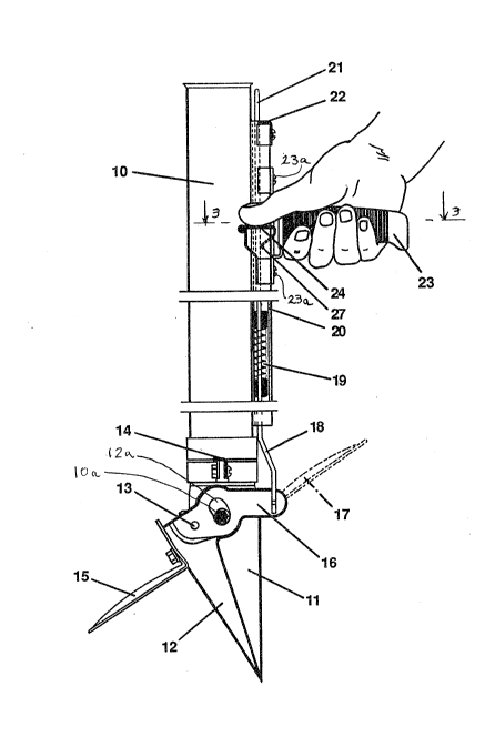
FIGURE 1 is a side elevational view of a -
planting tool according to the invention, with a portion
of a protective rail being shown in vertical section to
expose a spring;
FIGURE 2 is a vertical section through an upper
end of the latching rail; and
FIGURE 3 is a horizontal section taken through
the handle along the line 3-3 in FIG. 1.
Detailed Description of Preferred
Embodiments of the Invention
The planting tool comprises an upwardly open
tube 10 of such a diameter that a plant will fall
unaidedly throu~h it by its own weight. A beak half 11
i~ fixedly attached to the lower end of the tube, and a
hinged beak half 12 is hingedly attached to the tube by
a shaft 13. At least one foot plate 14 rigidly e~tends
from the tube in a direction parallel to the shaft 13.
Joined fixedly to the hinged beak half are
a lever 16 pointing towards the operator and a ground
plate 15 normally pointing away from the operator.
Alternatively, the ground plate 15 could be replaced by
a pedal 17 connected to the hinged beak half and pointing
7 ~
towards the operator. The lever 16 is connected to a
drawbar 18 which is pulled upwards by a spring 19. The
drawbar 18 is surrounded by a vertical protective rail 20
attached along an outside surface of the tube 10 to
prevent damage to the drawbar and blocking of the motion
of the drawbar 18 by twigs or debris. The rail is
preferably U-shaped in cross-section (see FIG. 3).
The drawbar 18 is preferably ~ade such that its upper
end 21 has a free equilibrium position spaced some
distance from the outside surface of the tube either
because of a slight elastic curvature of that upper end
or because of the action of a separate spring (not
shown).
An angular latch restraint 22 is attached to
the upper end of the rail 20. In a lower position of the
drawbar 18, corresponding to a fully open beak, an upper
end 21 of the drawbar does not extend above a reference
edge 26 of the restraint 22, but rather rests against an
inside corner 25 of the restraint under the influence of
the spring 19 in order to latch the beak in the open
condition. When the beak is partly or fully closed,
the upper end 21 of the drawbar will extend above the
restraint 22 by extending through an opening formed
between the tube 10 and the inner reference edge 26 of
the restraint. The upper end 21 of the drawbar will then
be visible outside of the rail 20 and is painted in a
striking warning color, indicating to the operator that
the tube must not be lifted from the plant.
2 ~ '7 ~ `
A handle 23 is attached to the rail 20 by
screws 23a. By loosening those screws, the handle 23
can be slid vertically relative to the tube to enable the
tool to be adjusted to the height of the operator.
Pivotably mounted on the handle 23 by means o
pivot pins 28 is a trigger 24 which includes a bridge
portion 24a carrying a tongue 27. When the trigger is
rotated downwardly by the thumb of the operator (i.e.,
rotated clockwise in Fig. 1), the bridge moves
horizontally within a slot (not shown) formed between the
rail 20 and the handle 23 whereby the tongue 27 presses
the drawbar 18 towards the tuhe 10. This allows the
upper end 21 of the drawbar to move upwardly past the
edge 26 of the restraint 22 under the action of the
spring 19 which closes the beak. The trigger 24 is
symmetrical, i.e., has thumb-contacting portions at each
side of the rail, to permit holding of the handle 23 with
a right or left hand. The rail 20 contains a vertical
slot 20a which permits vertical movement of the tongue 27
when the handle 23 is adjusted.
Operation of the Invention
For planting a tree plant the beak shall
initially be closed with the fixed beak half 11 in tigh~
contact with the hinged beak half 12. This is indicated
to the operator by the visible warning color of the
exposed upper end 21 of the drawbar. With one foot
on the foot plate 14 and the lower end of the tube 10
pointing slightly forward, the beak is pressed into the
ground so deeply that the ground plate 15 touches the
- 2 ~ iL ~
soil surface. Then, the upper end of the tube with the
handle 23 is moved forward by the operator to a vertical
position. In so doing, a guide pin lOa affixed to the
fixed beak half rides in a curved guide slot 12a formed
in the lever 16. The fixed beak half 11 thereby loosens
some soil towards the operator to make a planting hole.
The ground plate 15 prevents the hinged beak half 12 from
taking part in this motion, resulting in opening of the
beak when the fixed beak half 11 moves. When the tube
has been brought so far forward that the beak is fully
open, the upper end 21 of the drawbar will have been
pulled downwardly below the edge 26 of the restraining 22
and the drawbar 25 of the restraint, thereby latching the
beak in the open position. This is indicated hy the
warning color of the upper end 21 becoming hidden by
the restraint, and/or by the sound of the upper end 21
striking the corner 25.
The plant is then dropped through the tube and
into the hole. The operator may then check to verify
that the upper indicator portion of the drawbar is still
not visible, indicating that the planting tube can be
lifted without damaging the plant. Thereafter, the soil
loosened by the fixed beak half 11 on the side of the
hole towards the operator can be compacted with the foot.
By pressing the trigger 24 with the thumb, the upper
end 21 of the drawbar is freed from the corner 25 of the
restraining 22, causing the beak to close and making the
warning color visible once again.
1. 7 ~ ~ ~
For those who prefer a different mode of
operation, the ground plate 15 can be removed and
replaced by a pedal 17 attached to the hinged beak half
and pointing towards the operator. In this mode the beak
is pressed into the ground by the pressure of the foot on
the foot plate 14 with the tube vertical, whereupon the
beak is opened by depressing the pedal 17 until the beak
is fully open. In this mode, the loosened soil is on the
far side of the hole away from the operator, who has to
take a step obliquely forward
before being able to compact the soil with the foot.
A planting tube according to the invention can
be made from metal or plastics in a known manner.- The
fixed beak half and the rail can be made integral with
the tube, or separately fabricated.
Although the present invention has been
described in connection with preferred embodiments
thereof, it will be appreciated by those skilled in the
art that additions, modifications, substitutions, and
deletions not specifically described may be made without
departing from the spirit and scope of the invention as
defined in the appended claims.