Note: Descriptions are shown in the official language in which they were submitted.
- 1 2~726~
INDIVIDUAL CYLINDER AIR/FUEL RATIO
FEEDBACK CO~TROL SYSTEM
BACKGROUND OF THE INVENTION
The invention relates to feedback control
systems. In one particular aspect, the invention relates
to individual cylinder air~fuel ratio feedback control
systems for internal combustion engines.
In a typical fuel injected internal combustion
engine, electronically actuated fuel injectors inject
fuel into the intake manifold where it is mixed with air
for induction into the en~ine cylindèrs. During open
loop operation, inducted air flow is measured and a
corresponding amount of fuel is injected such that the
intake air/fuel ratio is near a desired value.
Air/fuel ratio feedback control systems are also
known for controlling the average air~fuel ratio among
the cylinders. In a typical system, an exhaust gas
oxygen sensor is positioned in the engine exhaust for
providing a rough indicakion of actual air~fuel ratio.
These sensors are usually switching sensors which switch
between lean and rich operation. The conventional
air/fuel ratio control systam coxrects the open loop fuel
calculation in response to the exhaust gas oxygen content
for maintaining the average air~fuel ratios among the
cylinders around a reference value. Typically, the
reference value is chosen to be within the operating
window of a three-way catalytic converter (NOX, CO, and
HC) for maximizing converter efficiency.
A problem with the conventional air/fuel ratio
control system is that only the average air~fuel ratio
among cylinders is controlled. There may be variations
in the air/fuel ratio of each cylinder even though the
average of all cylinders is corrected to be a desired
value. Variations in fuel injector tolerances, component
?.~1726~
aging, engine thermodynamics, air~fuel mixing through the
intake manifold, and variations in fluid flow into each
cylinder may cause maldistribution of air/fuel ratio
among each cylinder. This maldistribution results in
less than optimal performance. Further, air/fuel ratio
variations may cause rapid switching, referred to as
buzzing, and saturation of the EGO sensor~
One approach to reyulating air~fuel ratio on an
individual cylinder basis is described in U.S. Patent No.
4,483,300 issued to Hosoka et al. In this approach,
small variations in a two-state switching EGO sensor are
measured to, allegedly, determine fluctuations in
individual cylinder air/fuel characteristics. In
response to this measurement, the appropriate lnjector is
regulated. The inventors herein contend that, at best,
it is difficult to measure such small variations in the
EGO output, and such measurement would have a poor
signal~noise ratio. Fuxther, the typical EGO sensor is
easily saturated such that the needed signal variations
may not be available. .
The inventors herein have recognized that
maldistribution of air/fuel ratio among the cylinders
results in periodic, time variant, fluctuations in the
EGO sensor output. For example, if one cylinder is
offset in a rich direction, the EGO signal would
periodically show a rich perturbation during a time
associated with combustion in that cylinder.
Accordingly, conventional feedback control techniques,
which require nonperiodic inputs, are not amenable to
individual cylinder air/~uel ratio control.
$UMMARY OF THE INVENTION
An object of the invention herein is to provide
a sampled control system for maintaining the air/fuel
ratio of each cylinder at substantially a desired
2~72~6
air/fuel ratio. The above problems and disadvantages are
overcome, and object achieved, b~ providing both a
control system and a method for correcting air/fuel
ratios for each of N cylinders via an oxygen sensor
positioned in the exhaust of an internal combustion
engine. In one particular aspect of the invention, the
method comprises the steps oE: sampling the sensor once
each period associated with a combustion event in one of
the cylinders to generate N periodic output signals;
storing each of the N periodic output signals;
concurrently reading each of the N periodic output
signals from the storage once each output period to
define N nonperiodic correction signals each being
related to the air~fuel ratio of a corresponding cylinder
wherein the output period is defined as a predeterrnined
number of engine revolutions required for each of the
cylinders to have a single combustion event; and
correcting a mixture of air and fuel supplied to each of
the cylinders in response to each of the correction
signals.
By utilizing the sampling and rëading steps
described above, an advantage is obtained of converting a
periodic, time variant, sensor output into a ~onperiodic,
time invariant, signal. Thus, conventional feedback
control techniques may be used to advantage for obtaining
individual cylinder air/fuel ratio control which was not
heretofore possible.
In another aspect o the invention, the method
comprises the steps of: providing a correction signal in
response to the oxygen sensor related to an offset in
average air/fuel ratio among all the cylinders;
correcting a reference air/fuel ratio signal in response
to the correction signal; generating a single desired
fuel charge for delivery to each of the cylinders to
provide a desired average air/fuel ratio among all the
2 ~ 2 ~ 6
cylinders; sampling the oxygen sensor once each period
associated with a combustion event in one of the
cylinders to generate N periodic output signals; storing
each of the N periodic output signals; concurrently
reading each of the N periodic output signals from the
storage once each output period to define N nonperiodic
correction signals each being related to the airffuel
ratio of a corresponding cylinder wherein the output
period is defined as a predetermined number of engine
revolutions required for each of the cylinders to have a
single combustion event; and correcting the desired fuel
charge to generate a separate corrected fuel charge for
each of the cylinders in response to each of the
correction signals thereby providing a desired air/fuel
ratio for each of the cylinders.
An advantage of the above aspect of the
invention is that the average air~fuel ratio among the
cylinders is corrected on an individual cylinder hasis by
utilizing known feedback control techniques.
BRIEF DESCRIPTION OF THE DRAWINGS
The objects and advantages described herein will
be more fully understood by reading the Description of
the Preferred Embodiment with reference to the drawings
wherein:
Figure 1 is a block diagram of a system wherein
the invention is utilized to advantage;
Figure 2 is a flow diagram of various process
steps performed by the embodiment shown in Figure l;
Figure 3 is a graphical representation of signal
sampling described with reference to Figures 1 and 2;
Figure 4A is a graphical representation of
various control signals generated by the embodiment shown
in Figure l;
2~:~72~
-- s ~
Figure 4B is a graphical representation of the
effect the control signals illustrated in Figure 4A have
on airffuel ratio; and
Figure 5 is an alternate embodiment to the
embodiment shown in Figure 1.
DESCRIPTION OF THE PREFERRED EMBODIMENT
Referring to Figure 1, in general terms which
are described in greater detail later herein, internal
combustion engine 12 is shown coupled to fuel controller
14, average airifuel controller 16, and individual
cylinder air/fuel controller 18. In this particular
e~ample which is referred to as a preferred embodiment,
engine 12 is a 4-cycle, 4-cylinder internal combustion
engine having intake manifold 22 with electronically
actuated fuel injectors 31, 32, 33, and 34 coupled
thereto in proximity to respective combustion cylinders
41, 42, 43, and 44 (not shown). This type of fuel
injection system is commonly referred to as port
injection. Air intake 58, having mass air flow meter 60
and throttle plate 62 coupled thereto, is shown
communicating with intake manifold 22.
Fuel rail 48 is shown connected to fuel
injectors 31, 32, 33, and 34 for supplying pressurized
fuel from a conventional fuel tank and fuel pump (not
shown~ Fuel injectors 31, 32, 33, and 34 are
electronically actuated by respective signals pwl,
pw2, pw3, and pw4 from fuel controller 14 for
supplying fuel to respective cylinders 41, 42, 43, and 44
3~ in proportion to the pulse width of signals pwl 4.
Exhaust gas oxygen sensor (EGO) 70, a
conventional 2-state EGO sensor in this example, provides
via filter 74 an ego signal related to the average
air/fuel ratio among cylinders 41-44. When the average
air/fuel ratio among cylinders 41-44 rises above a
2~ 72~
-- 6 --
reference value, EGO sensor 70 switches to a high
output. Similarly, when the average air~uel ratio among
cylinders 41-44 falls below a reference value, EGO sensor
70 switches to a low output. This reference valu0 is
typically correlated with an airffuel ratio of 14.7 lbs
air per 1 lb o fuel and is referred to herein as
stoichiometry. The operating window of 3-way catalytic
converter 76 is centered at stoichiometry for maximizing
the amounts of NO~, CO, and HC emissions to be
removed.
As described in greater detail later herein,
average air/fuel con~roller 16 provides fuel demand
signal fd in response to mass air flow (MAF) signal from
mass air flow meter 6Q and the feedback ego signal from
EGO sensor 70. Fuel demand siynal d is provided such
that fuel injectors 31-34 will collectively deliver the
demanded amount of fuel for achieving an averaqe air/fuel
ratio among the cylinders of 14.7 lbs air/lb fuel in this
particular example.
Individual cylinder air/fuel controller 18
provides trim signals tl, t2, t3, and t4 in
response to the feedback ego signal and other system
state variables such as engine speed ~RPM) and eng;ne
load or throttle angle (TA). Trim signals tl 4 provide
corrections to fuel demand signal fd for achieving the
desired air/fuel ratio for each individual cylinder. In
this particular example, trim signals tl 4 correct fuel
demand signal fd via respective summers 80, 82, 84, and
86 for providing corrected fuel demand signals fdl,
fd2, fd3, and fd4. Fuel controller 14 then
provides electronic signals pwl 4, each having a pulse
width related to respective fdl 4 signals, such that
injectors 31-34 provide a fuel amount for achieving the
desired air/fuel ratio in each individual cylinder.
-- 7 --
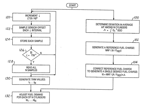
Continuing with Figure 1, and process steps 100,
102 and 104 shown in Figure 2, the structure and
operation of average air/fuel controller 16 is now
described in more detail. Avera~e air~fuel controller 16
includes conventional feedback controller 90, a
proportional integral feedback controller in this
example, and multiplier 92. In a conventional manner,
feedback controller 90 generates corrective factor lambda
(~) by multiplying the ego signal by a gain Eactor
(Gl~ and integrating as shown by step 100. Correction
factor ~ is therefore related to the deviation in
average air/fuel ratio among cylinders 1-4 from the
reference air/fuel ratio. Multiplier 92 multiplies the
inverse of the reference or desired air~fuel ratio times
the MAF signal to achieve a reference fuel charge. This
value is then offset by correction factor ~ from
feedback controller 90 to generate desired fuel charge
signal fd.
It is noted that average air~fuel ratio control
is limited to maintaining the average air/fuel ratio
among the cylinders near a reference value. The air~fuel
ratio will most likely vary among each cylinder due to
such factors as fuel injector tolerances and wear, engine
thermodynamics, variations in airJfuel mixing through
intake manifold 22, and variations in cylinder
compression and intake flow. These variations in
individual cylinder air~fuel ratios result in less than
optimal performance. Further, a cylinder having an
offset air/fuel ratio leads to periodic excursions in
exhaust gas oxygen content possibly resulting in periodic
saturation of EGO sensor 76 and also rapid oscillations
in average air/fuel ratio (see Figure 4 between times
To and T5). Individual cylinder air/fuel controller
18 solves these problems as described below.
2~ 726~
-- 8 --
Referring back to Figure 1, individual cylinder
air/fuel controller 18 is shown including demultiplex~r
108, synchronizer 110, observer 112, controller 114, and
timing circuit 116. In general, demultiplexer 108 and
synchronizer 110 convert the time varying, periodic
output of the ego signal into time invariant, sampled
signals suitable for processing in a conventional
feedback controller. Stated another way, the ego signal
is time variant or periodic because variations in
individual air/fuel ratios of the cylinders result in
periodic fluctuations of the eæhaust output. These
periodic variations are not amenable to feedback control
by conventional techniques. Demultiplexer 108 and
synchronizer 110 convert the ego signal into four
individual signals (Sl, S2, S3, and S4) which are
time invariant or nonperiodic. Observer 112 correlates
information from signals Sl ~ to the previous
combustion event for each cylinder.
The operation of individual cylinder air/fuel
controller 18 is now described in more detail with
continuing reference to Figure 1, reference to the
process step shown in Figure 2, reference to the
graphical representation of the ego signal shown in
Figure 3, and reference to the graphical representation
of controller 18 output shown with its effect on overall
air/fuel ratio in Figures 4A and 4B. Demultiple~er 108
includes a conventional A/D converter (not shown) sampled
every 720/N, for a four stroke engine, where N = the
number of engine cylinders. In the case of a 2-cycle
engine, the sample rate (i) is 360/N. For the example
presented herein, N = 4 such that the sample rate (i) is
180. Referring to steps 120, 122, 124, and 126, the ego
signal is sampled at a sample rate (i) of 180 until four
samples (Sl 4) are taken (i.e. 720~. Each sample is
stored in a separate storage location.
~7`2~6
g
ReEerring for illustrative purposes to Figure 3,
an expanded view of the ego signal is shown. Samples
Sl 4 are shown taken every 180 for a 720 output
period associated with one engine cycle. During a
subsequent engine cycle, another four samples ~Sl 4')
are taken. It is also shown in this eæample that the
sampled values of the ego signal are limited to an upper
threshold associated with lean operation (1 volt in this
eæample) and a lower threshold associated with rich
operation (minus one volt in this example~. This 2-state
sample inormation has been found to be adequate for
achieving individual air/fuel ratio control.
Referring to synchronizer 110 shown in Figure 1,
and step 128 in Figure 2, all our samples ~Sl 4) are
simultaneously read from storage each output period of
720. Accordingly, on each 720 output period, four
simultaneous samples are read which are now time
invariant or nonperiodic sampled signals. In response to
each sampled signal (Sl 4), and also in response to
engine speed (RPM) and engine load (TA) signals, observer
112 predicts the air/fuel ratio conditions in the
corresponding cylinder utilizing conventional
techniques. For example, at a particular engine speed
and load, a combustion event in one cylinder will effect
the ego signal a predetermined time afterwards.
Controller 114, a proportional integral
controller operating at a sample rate of 720 in this
eæample, then generates four trim values tl, t2,
t3, and t4 as shown by step 130 in Figure 2. Each
trim value is then added to, or subtracted from, fuel
demand signal fd in respective summers 80, 82, 84, and 86
to generate respective individual fuel demand signals
fdl, fd2, fd3, and fd4 as shown by step 132. In
response, fuel controller 14 provides corresponding pulse
width signals pwl_4 for actuating respecti~e fuel
2~ ~2~6
-- 10 --
injectors 31-34.
The affect of individual cylinder air~fuel
feedback controller 18 is shown graphically in Figures 4A
and 4B. For the particular example shown -therein,
cylinder one is running lean, and cylinders three and
four are running rich. The corresponding airffuel ratio
is shown rapidly switching under contrvl of average
air/uel controller 16 before time T5 for reasons
described previously herein. By time T5 individual
cylinder air~fuel controller 18 fully generates trim
signals tl 4 such that each individual cylinder is
operating near the reference air/fuel ratio. The
corresponding average airffuel ratio is therefore shown
entering a desired switching mode after time T5. Any
switching excursions shown are inherent to a proportional
integral feedback control and are within limits of EGO
sensor 70.
An alternate embodiment in which the invention
is used to advantage is shown in Figure 5 wherein like
numerals refer to like parts shown in Figure 1. The
structure shown in Figure 5 is substantially similar to
that shown in Figure 1 with the exception that trim
signals tl 4 are multiplexed in multiplexer 140' and,
accordingly, only one summer (80') is needed. Since fuel
delivery to each cylinder is sequenced in 180
increments, trim signals tl 4 are serially provided to
summer 80' for modifying fuel demand signal fd. In thi~
manner, fuel demand signal fd is trimmed in a time
sequence corresponding to fuel delivery for the cylinder
being controlled. Other than this multiplexing scheme,
the operation of the embodiment shown in Figure 5 is
substantially the same as the operation of the embodiment
shown in Figure 1.
This concludes the Description of the Preferred
Embodiment. The reading of it by those skilled in the
:
~72~
-- 11
art will bring to mind many alterations and modifications
without departing from the spirit and scope of the
invention. For example, the invention described herein
is e~ually applicable to 2-stroke engines. It may also
be used to advantage with engines having any number of
cylinders and fuel injection systems different from those
described herein. A banked fuel injection system wherein
groups or banks of fuel injectors are simultaneously
fired is an example of another type o fuel injection
system in which the invention may be used to advantage.
Accordingly, it is intended that the scope of the
invention be limited only by the following claims.
3G