Note: Descriptions are shown in the official language in which they were submitted.
2~7~
PA-5681-0-DW-USA
LOWER SPRAY ARM FOR DISHWASHER
Backqround of the Invention
Eield of the Invention
The present invention relates to spray arms for dis-
tributing fluid from a pressurized supply into a
dishwasher wash chamber and, more particularly, to a
spray arm with a telescoping spray tower and a method of
forming the same.
Description of the Prior Art
It is known to provide one or more extensible spray
tower sections on a rotary dishwasher spray arm to
enhance the distribution of water from a pressurized
fluid supply in a wash chamber. One exemplary prior art
structure is shown in U.S. Patent 3,866,837, to Jenkins.
In Jenkins '837, a spray tower is inserted, during the
assembly process, through an opening in the top of the
spray arm. Subsequent to the placement of the spray
tower in the spray arm opening, a retainer cap is
threaded onto the spray arm to prevent separation of the
tower from the spray arm.
One drawback with the Jenkins '837 structure is that
there is a potential leak point for incoming fluid
between the retainer cap and the spray arm, which may
diminish the pressure of the fluid in the tower.
A further drawback with the structure in Jenkins
'837 is that the entire spray arm assembly is relatively
complicated from a manufacturing standpoint.
*
- -
2 ~ 3 ~ ~3
PA-5681-0-DW-USA
Summary of the Invention
The present invention is specifically directed to
overcoming the above enumerated problems in a novel and
simple manner.
According to the invention, a spray arm assembly for
delivering a fluid under pressure into a dishwasher wash
chamber consists of a spray arm having a rotational axis
and defining a fluid passageway for distributing incoming
fluid into the wash chamber, a tower section, structure
for mounting the tower section to the spray arm for
guided movement relative to the spray arm between a
retracted position and an extended position, and
structure on the tower section for directing fluid from
the fluid supply into the wash chamber with the tower
section in its extended position. Mounting structure,
integrally formed with the spray arm, prevents the tower
section from separating from the spray arm with the tower
section in its extended position. Any number of
cooperating tower sections can be employed.-
With the inventive structure, the spray arm and
tower can be preassembled as an inseparable, operative
assembly. Facilitated connection of the entire spray arm
assembly to the remainder of the dishwasher results.
In a preferred form of the invention, the spray arm
is defined by at least two permanently fused spray arm
sections. There is cooperating structure on the tower
section and the two fused spray arm sections to prevent
the tower section from separating from the spray arm. In
one form of the invention, the tower section has a lip
which encounters an integrally formed shoulder on one of
~$!,
2~3~6
PA-5681-0-DW-USA
the spray arm sections to arrest movement of the tower
section relative to the one spray arm section in one
direction and the lip abuts a wall spaced from the
shoulder and integrally formed with the other spray arm
section to limit movement of the tower section relative
to the spray arm in a direction opposite the one
direction.
The invention also comprehends a method of forming
the spray arm assembly. First and second separate,
10 joinable spray arm sections are provided. One of the
spray arm sections has an opening to receive the tower
section, which is directed through the opening prior to
the connection of the spray arm sections to each other.
Preferably, the spray arm section with the tower re-
15 ceiving opening is inverted and the tower section is
directed through the opening in the section and suspended
from the one spray arm section by the lip on the tower
section. Fusion of the spray arm sections is carried out
with the spray arm inverted.
To facilitate connection of the spray arm assembly
to a fluid pump, a support sleeve and nut are provided.
The nut surrounds the bottom of the spray arm and is
attached thereto from the bottom of the spray arm. The
support sleeve is also attached to the spray arm from the
25 bottom thereof and captively maintains the nut against
the spray arm in operative position wherein it is used to
secure the support sleeve and the attached spray arm to
the fluid pump.
With this arrangement, the nut and support sleeve
30 can be attached to the spray arm assembly from one side
r~
PA-5681-0-DW-USA
20 1 7386
and the securing of the support sleeve to the spray arm
can be accomplished from the same side, as by a screw.
This arrangement facilitates automated assembly of the
spray arm assembly, the support sleeve and nut.
Preferably, the support sleeve and screw are
preassembled using a retaining washer. A bearing is
placed between the screw and support sleeve. The
retaining washer also maintains a slight spacing between
the assembled support sleeve and spray arm to permit free
relative rotation therebetween.
---~ A sealing ring is provided and situated between the
spray arm and the subassembly, consisting of the support
sleeve, screw and bearing, and blocks passage of fluid
between the spray arm and support sleeve subassembly.
Brief Description of the Drawings
Fig. 1 is a perspective view of a dishwasher having
a preferred form of spray arm assembly according to the
present invention incorporated therein;
Fig. 2 is an enlarged section view of the spray arm
assembly taken along line 2-2 of Fig. l;
Fig. 3 is an enlarged, exploded view of the spray
arm assembly, partially in section;
Fig. 4 is an elevation view of the spray arm
assembly shown in an inverted position during assembly;
and
Fig. 5 is an enlarged, section view of the spray arm
assembly taken along line 5-5 of Fig. 4.
~x- :
20 1 7 3 ~6
Detailed DescriPtion of the Drawinqs
In Fig. 1, a spray arm assembly, according to the
present invention, is shown at 10 incorporated into a
dishwasher 12 shown mounted under a counter 14. The
dishwasher 12 is only intended to be representative of
one type of dishwasher into which the inventive spray arm
assembly 10 can be incorporated.
The dishwasher 12 has a cabinet 16 defining a wash
chamber 18 within which dishes and utensils are supported
on racks (not shown) for treatment. The wash chamber 18
is selectively sealed by a hinged door 20, which is
pivotable about its lower edge 22 between the closed
-~ position, shown in Fig. 1, and an open position, wherein
access can be gained to the wash chamber 18. A control
console 24 is incorporated into the top of the door 20
and has a latch 26 to selectively lock and release the
door 20.
The spray arm assembly 10, which includes a spray
arm 27 and a tower 28, resides within the wash chamber 18
and during operation distributes a supply of water deliv-
ered under pressure by a pump 29 throughout the wash
chamber 18. Details of the spray arm assembly 10 are
shown clearly in Figs. 2-5.
The spray arm assembly 10 is supported on a raised
pedestal at 30 at the bottom of the wash chamber 18. The
pedestal 30 consists of a pump outlet conduit 32
surrounded by a raised portion of a liner 34 which bounds
the wash chamber 18. The liner 34 has an opening 36
through which the pump outlet conduit 32 projects. A
gasket 38 and a washer 39, vented at 41, together prevent
PA-5681-0-DW-USA
20 1 7386
the escape of fluid from the wash chamber 18 around the
conduit 32 and underneath the raised portion of the liner
34 where it could potentially come into contact with the
pump 29.
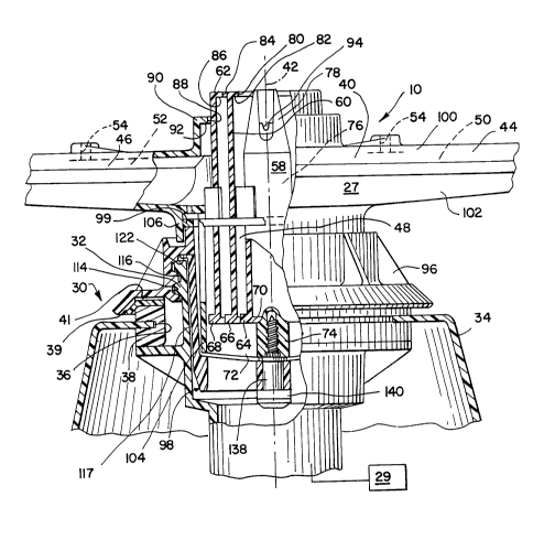
The spray arm 27 consists of a cylindrical hub 40
having a vertical rotational axis 42 and integral,
radially projecting conduits 44, 46. The hub 40 defines
a passageway 48 for communicating fluid under pressure
from the pump 29 upwardly and to radially outwardly
extending fluid passageways 50, 52, defined by conduits
44, 46 respectively. The conduits 44, 46 have discharge
openings 54 for directing the pressurized fluid from the
passageways 50, 52 directly into the wash chamber 18.
To further distribute incoming fluid from the pump
29 in the wash chamber 18, the extendable tower 28 is
provided in the hollow 48 of the spray arm hub 40. The
tower 28 consists of three telescopingly mated,
cylindrical, hollow sections 58, 60, 62.
The tower sections 58, 60, 62 are normally in a col-
lapsed/retracted position, shown in Figs. 2 and 3. The
sections 58, 60, 62 have, at the bottom thereof, radially
extending lips 64, 66, 68, consecutively, which are borne
by an upwardly facing wall surface 70 defined
cooperatively by a plurality of ribs 72 extending radi-
ally from a central hub 74 at the bottom of the spray arm
27.
Fluid under pressure from the pump 29 exits the
conduit 32 and flows upwardly into the hollow 76 of the
radially innermost tower section 58 and impinges against
the converging inside surface of the upper end 78 of the
PA-5681-0-DW-~SA
20 1 7386
tower section 58, thereby causing the tower section 58 to
move upwardly guidingly through an opening 80 in the
surrounding tower sectlon 60. The lip 64 on tower
section 58 has a larger diameter than the opening 80 and,
as it rises, comes into contact with a downwardly facing
shoulder 82 on the tower section 60 so that continued
movement of the tower section 58 unseats the tower
section 60. The tower section 60 is free to move
upwardly through an opening 84 in the tower section 62
until the lip 66 encounters a downwardly facing shoulder
86 on tower section 62 surrounding the opening 84. The
lip 66 in turn draws the tower section 62 upwardly and
through an opening 88 in a fixed wall 90 at the top of
and integrally formed with the spray arm 27 until the lip
68 abuts a downwardly facing shoulder 92 surrounding the
openi-.g 88 and its vertical movement is arrested. In the
fully extended tower position, fluid from the pump
conduit 32 flows freely consecutively through the
conduits 62, 60, 58 and is discharged through openings 94
in the tower 58 into the wash chamber 18.
According to the invention, the spray arm assembly
10 is formed as a self-contained operable unit which is
attached to the pump conduit 32 through the use of a nut
96 and support sleeve subassembly 98, and sealed by a
split ring 99, as described later herein. The spray arm
27 is formed in two sections - an upper spray arm section
- 100 and a lower spray arm section 102. The lower spray
arm section 102 may be formed in one piece or may be a
preassembled subassembly consisting of a cup-shaped tower
receptacle 104 defining the wall surface 70 nested in and
-- o ~ :
PA-5681-0-DW-USA
20 1 7386
fused with a depending annular skirt 106 on the lower
- spray arm section 102.
To assemble the spray arm assembly 10, the tower
sections 58, 60, 62 are nested, one within the other, and
directed through the opening 88 in the upper spray arm
section 100 from the bottom up. This is more readily
accomplished with the spray arm section 100 inverted, as
shown in Fig. 4, so that the tower sections 58, 60, 62
hang in a fully extended position from the wall 90 of the
upper section 100 by their respective lips 64, 66, 68.
The upwardly facing edge 108 of the inverted tower
section 100 is heat sealed to the downwardly facing edge
110 of the inverted lower support arm section 102 in
conventional fashion to fuse the spray arm sections 100,
102 in fluid tight fashion. The fused sections 100, 102
cooperatively bound the fluid passageways 50, 52, as seen
clearly in Fig. 5.
With the spray arm sections 100, 102 fused, it can
be seen that the tower sections 58, 60, 62 are
permanently maintained captive between the shoulder 92 on
the wall so of the upper spray arm section loo and the
wall surface 70 on the lower spray arm section 102. The
result is that no further assembly is required to opera-
tively interconnect the towers 58, 60, 62 and spray arm
27, and the resulting assembly 10 can be in turn
connected as an operable unit to the fluid conduit 32
projecting up through the pedestal 30.
The nut 96 is used to attach the spray arm assembly
10 to the conduit 32. The nut 96 surrounds the outer
surface 112 of the tower receptacle 104 and has threads
PA-5681-0-DW-USA
20 1 7386
114 to engage threads 116 on the conduit 32. Before the
nut 96 is threaded onto the conduit 32, the split ring 99
is put in place. The configuration of a suitable split
ring 99 and its relationship to the remainder of the
spray arm assembly 10 and pedestal 30 are described fully
in U.S. Patent 4,732,323, assigned to Whirlpool
Corporation.
~he support sleeve subassembly 98 has a sleeve 117
that is generally cup-shaped and has an enlarged,
radially extending flange 118 at the top thereof. The
body 120 of the sleeve 117 surrounds the tower receptacle
104 on the lower spray arm section 102 and nests in an
undercut 122 on the nut 96. With the uppermost surface
124 of the sleeve 117 abutting the downwardly facing
annular shoulder 126 defined by the undercut 122, the
bottom surface 128, defined cooperatively by the ribs 72
and hub 74, can be brought into close proximity with an
upwardly facing surface 130 on the support sleeve 117,
which surface 130 is defined cooperatively by a hub 132
and a plurality of ribs 134 extending radially from the
hub 132. The bottom surface 128 on the spray arm 27
conforms closely in contour to the surface 130.
The support sleeve subassembly 98 further includes a
washer 136, a shoulder screw 138 and a bearing 140, all
of which are pre-assembled to the support sleeve 117.
The shoulder screw 138 is directed upwardly consecutively
through the bearing 140, a bore 142 in the support sleeve
117 and the washer 136, which maintains the shoulder
screw 138 in place on the sleeve 117. After preassembly
of the support sleeve subassembly 98 the shoulder screw
PA-5681-0-DW-USA
20 1 7386
138 is directed into a threaded bore 144 in the hub 74 on
- the lower spray arm section 102. The lower spray arm
section 102 and screw 138 rotate as a unit and the
unthreaded portion 146 of the screw 138 is guided
smoothly in rotation within the support sleeve bore 142.
The washer 136, interposed between the hub 74 on the
lower spray arm section 102 and the hub 132 on the
support sleeve 117, maintains a slight spacing between
the facing surfaces 128, 130 to thereby permit
substantially uninhibited relative rotation between the
lower spray arm section 102 and the support sleeve 117.
The support sleeve subassembly 98 is preferably
preassembled with the remainder of the spray arm assembly
10 before the support sleeve 117 is put in place around
the,tower receptacle 104 and before the spray arm assembly
10 is attached to the pump conduit 32. Once assembly of
the sleeve subassembly 98 has occurred, the sleeve 117 is
directed into the bore 148 of the conduit 32. A close
friction fit between the sleeve 117 and conduit 32 is
enhanced by a plurality of circumferentially spaced,
deformable ribs 150 on the sleeve 117, which ribs 150 are
s~ueezed tightly between the body 120 of the sleeve 117
and the conduit surface surrounding the bore 148. With
the sleeve 117 extended fully downwardly within the bore
148, a downwardly facing, annular surface 152 on the
flange 118 bears on the free upper edge 154 of the
conduit 32. The nut 96 is then threaded down onto the
conduit 32 and in the process nut shoulder 126 bears down
and positively presses the sleeve flange 118 against the
conduit edge 154.
.
-
PA-5681-0-DW-USA
20 1 7386
With the inventive structure, the sleeve subassembly
98 can be preassembled and thereafter connected to the
lower spray arm section 102 to produce the self-contained
spray arm assembly 10. The split ring 99 is captively
maintained in operative position between the support
sleeve subassembly 98 and the spray arm 27. The
attachment of the sleeve 117 and nut 96 is carried out
from one side of the spray arm assembly 10. That is, the
nut 96 is extended upwardly over the receptacle 104 and
in turn the sleeve subassembly 98 is directed upwardly
over the receptacle 104 to complete assembly. An entire
unit consisting of the spray arm 27, the tower 28, the
split ring 99, the nut 96, and sleeve subassembly 98 can
be put in place on the pedestal 30 and removed therefrom
simply by selectively tightening and loosening the
retaining nut 96.
The foregoing disclosure of specific embodiments is
intended to be illustrative of the broad concepts compre-
hende~ by the invention.