Language selection

Search

Patent 2017540 Summary

Third-party information liability

Some of the information on this Web page has been provided by external sources. The Government of Canada is not responsible for the accuracy, reliability or currency of the information supplied by external sources. Users wishing to rely upon this information should consult directly with the source of the information. Content provided by external sources is not subject to official languages, privacy and accessibility requirements.

Claims and Abstract availability

Any discrepancies in the text and image of the Claims and Abstract are due to differing posting times. Text of the Claims and Abstract are posted:

  • At the time the application is open to public inspection;
  • At the time of issue of the patent (grant).
(12) Patent: (11) CA 2017540
(54) English Title: FILLING CAR FOR A COKE OVEN BATTERY
(54) French Title: CHARIOT D'ALIMENTATION POUR BATTERIE DE FOUR A COKE
Status: Deemed expired
Bibliographic Data
(52) Canadian Patent Classification (CPC):
  • 202/48
(51) International Patent Classification (IPC):
  • C10B 31/02 (2006.01)
  • B65G 69/18 (2006.01)
  • C10B 31/04 (2006.01)
  • F16L 27/02 (2006.01)
(72) Inventors :
  • SCHROTER, HORST (Germany)
(73) Owners :
  • HARTUNG, KUHN & CO. MASCHINENFABRIK GMBH (Germany)
(71) Applicants :
(74) Agent: FETHERSTONHAUGH & CO.
(74) Associate agent:
(45) Issued: 1998-04-21
(22) Filed Date: 1990-05-25
(41) Open to Public Inspection: 1990-11-26
Examination requested: 1991-10-21
Availability of licence: N/A
(25) Language of filing: English

Patent Cooperation Treaty (PCT): No

(30) Application Priority Data:
Application No. Country/Territory Date
P39 17 116.7 Germany 1989-05-26

Abstracts

English Abstract


A filling car for filling coal in oven chambers of a
coke oven battery comprises a telescopable filling pipe having
an upper part and a lower part and a lower end to be lowerable
to a filling frame of a filling opening of a coke oven
battery, a supporting ring in which the lower part of the
filling pipe is supported for turning about a horizontal axis,
a liftable and lowerable supporting bracket in which the
supporting ring is held, means for suspending the lower part
of the filling pipe in the supporting ring and including two
oppositely located hinge arms, and means for holding the
supporting ring on the supporting bracket and including two
oppositely located pivot pins arranged so that the supporting
ring is turnable about a horizontal axis relative to the
supporting bracket, the hinge arms and the pivot pins being
offset relative to one another by 90°.


French Abstract

Le chariot de remplissage servant à verser du charbon dans des fours d'une batterie de fours à coke comprend un tuyau de remplissage télescopique ayant une partie supérieure et une partie inférieure et une extrémité inférieure abaissable jusqu'à un cadre de remplissage d'une ouverture de remplissage d'une batterie de fours à coke, un anneau support dans lequel la partie inférieure du tuyau de remplissage se loge afin de tourner autour d'un axe horizontal, une ferrure support relevable et abaissable dans laquelle l'anneau support est maintenu, des dispositifs pour suspendre la partie inférieure du tuyau de remplissage dans l'anneau support et comprenant deux bras articulés situés vis-à-vis, et des dispositifs pour maintenir l'anneau support sur la ferrure support et comprenant deux pivots situés vis-à-vis, disposés de façon que l'anneau support puisse tourner autour d'un axe horizontal par rapport à la ferrure support, les bras articulés et les pivots étant décalés les uns par rapport aux autres de 90 degrés.

Claims

Note: Claims are shown in the official language in which they were submitted.


1. A filling car for filling coal in oven chambers
of a coke oven battery, comprising a telescopable filling pipe
having an upper part and a lower part and a lower end to be
lowerable to a filling frame of a filling opening of a coke
oven battery; a supporting ring in which said lower part of
said filling pipe is supported for turning about a horizontal
axis; a liftable and lowerable supporting bracket in which
said supporting ring is held; means for suspending said lower
part of said filling pipe in said supporting ring and
including two oppositely located hinge arms; and means for
holding said supporting ring on said supporting bracket and
including two oppositely located pivot pins arranged so that
said supporting ring is turnable about a horizontal axis
relative to said supporting bracket, said hinge arms and
said pivot pins being offset relative to one another by 90°.


2. A filling car as defined in claim 1; and
further comprising means for sealing said lower part of said
filling pipe at upper and lower ends of said lower pipe.


-9-


3. A filling car as defined in claim 1,
wherein said sealing means being formed as sealing rings
arranged at the upper and lower ends of said lower part of
said sealing ring.


4. A filling car as defined in claim 3,
wherein said sealing rings are formed as spherical layers.


5. A filling car as defined in claim 1,
wherein said hinge arms have upper and lower ends provided
with hinge heads.


6. A filling car as defined in claim 5,
wherein said hinge heads of said hinge arms are spherical.


-10-

Description

Note: Descriptions are shown in the official language in which they were submitted.


~3~


The present invention relates to a filling car
for filling coal in oven chambers of a coke oven battery.
More particularly, it relates to such a filling car which
S has a telescopable filling pi~e lowerable with its lower end
on a filling frame of a filling opening of the coke oven
battery, and in which the lower part of the filling pipe is
suspended in a supporting ring turnable about a horizontal
axis, which is in turn is held on a lowerable and liftahle
supporking bracket.
D~lring operation of a filling car, it is necessary
in view of the modern requirements for labor and environmental
protection, to catch dust and tar containing gases produced
during filling of the oven chambers and to convey them to
the receiver of the coke oven battery. These gases are
subjected to different conditions during the filling process
and can escape due to negative pressure or insufficient
draw to the receiver through the filling openings. For
preventing this disadvantage, a reliable sealing between the
lower end of the filling pipe and the filling frame on
which the filling pipe is placed durin~g the filling process,
is required. In the practice, however, especially in old
coke oven batteries with uneven coke oven tops, this led
frequently to position inaccuracies of the filling cars. As
2s a result, the vertical central axis of the fixed filling pipe

:: :
~ -2-

,., . - --- - - : -
.
.

- - , . . .

,:
.
: . ' ' ,-: .
' ', ' :' .

~ 7~

1 of th~ coal contalner did not coincide with the vertical
central axis of the filling opening or the filling frame
and a greater or smaller offset produced between the central
axes. This offset could amount to several centimeters. For
providing a reliable sealing between the filling frame and
the upper part of the filling pipe it was required to i.ncline
the lower part of the filling pipe in correspondence with
the above ~nentioned offset. In many constructions this,
however, was not possible.
German document D~-PS 2,922,571 describes a filling
car in which the lower part of the filling pipe is suspended
in a supporting ring whlch is turned about a horizontal axis.
The supporting ring is held in turn in a liftable and
lowerable supporting bracket. In tllis construction however
the lower part of the filling pipe is turnable only in one
direction, and a swinging movement of the filling pipe in
this construction must be avoided. As a result, in this
construction during lowering of the filling pipe to the
filling frame, crescent-shaped untightness dependent on the
offset can be produced. The filling gases can escape through
such an untightness without any obstacle. If attempts are
made to forcedly eliminate this untig~htness, irreversible
damages can be done to the whole filling system.


. :

21~ 5~


Accordingly, it is an object of the pre3ent
invention to provide a filling car for coke oven batteries,
which avoids the disadvantages of the prior art.
More particularly, it is an object of the present
invention to provide a filling car for a coke oven battery,
in which the lower part of the filling pipe is guided so that
it can assume an inclined position corresponding to the offset
of the vertlcal central axes of the filling pipe and the
filling openiny and therefore provide a reliable sealing.
In keeping with these objects and with others which
will become apparent hereinafter, one feature of the present
invention resides, briefly stated, in a filling car in which
the suspension of the lower part of the filling pipe in the
supporting ring is performed by two oppositely located hinge
arms pxovided with upper and lower hinge heads, and the
supporting ring is supported in a supporting bracket turnably
about a horizontal a~is by means of two oppositely located
pivot pins, wherein the hinge arms and the pivot pins are
offset relative to one another by 90~.
: Due to this suspension, the lower part of the
filling pipe can perform a conical, spatial swinging movement
about its suspension point and therefore assume an inclined
position required for a reliable sealing of the filling pipe
and the filling opening.

.
--4--

" ., . , .: . . . ~ . .


; - , ~ ., :
,.
.

'
;: : ' :: :

r3~

1 In accordance with a further feature oP the present
invention, it is advantageous to arrange sealing ~inys at
upper and lower ends of the lower part of the filling pipe
to provide a realiable sealing between the upper and lower
parts of the filling pipe and between the lower part of the
filling pipe and the filling frame. Preferably, the sealing
rings can be formed as spherical layers.
With such a construction, the sealing rings in each
position of the lower part can exactly be adapted to both
the filling frame at the outlet of the lower part of the
filling pipe and to the filling frame. Therefore, a reliable
sealing is ensured.
The novel features which are considered as
characteristic for the invention are set forth in particular
in the appended claims. The invention itsel f, however, both
as to its construction and its method of operation, together
with additional ob]ects and advantages thereof, will be best
understood from the following description of specific
embodiments when read in connection with the accornpanying
drawings.


... .

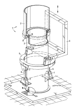
The single FIGURE of the drawings is a view showing
schematically a filling car for a coke oven battery in
accordance with the present invention.


,~,~.",.,, ., ,, ~ .


' ~

~ ~. 7 o~


A filling car for a coke oven battery has a filling
pipe which is identified as a whole with reference numeral 1.
The filling pipe 1 is telescopable and composed of an upper
part 2 and a lower part 3. It is arranged under an immovable
filling pipe of a coal container, and the upper end of the
upper part 2 surrounds the filling pipe of the coal container.
The coal container with its filling pipe and other details
of a filling car are not shown in the drawing, since they are
not important for an understanding of the present invenkion.
They can perform in correspondence wi.th the constructions of
the prior art.
The coal container with the associated filling pipe
is arranged above the filling pipe 1. Therefore, the coal
can flow under the action of gravity through the filling pipe
1 to an oven chamber of a coke oven battery indicated under
the filling pipe 1. The lower part 3 of the filling pipe 1
is lowered for thi5 purpose onto a filling frame ~. In
order to perform the lowering, the lower part 3 is suspended
in a supporting ring 5 by two oppositely located hinge arms
6. The hinge arms 6 are provided with~spherically shaped
hinge heads 7 on their upper and lower ends to ensure the
desired movability of the lower part 3.
The supporting ring is mounted in turn on a
supporting bracket 9 by two oppositely located rotary pins 8

-6-


, , ~ ,
~ : ~ : : :
~ ' ' ' '; '
:'
: ,
.. ~, ....


:

1 and is turnable about a horizontal axis. A ,suppoxting
bracket 9 ls liftable and lowerable as identified in the
drawing with the double arrow. By the respective movement cf
the supporting bracket 9, the lower part 3 of the filling pipe
1 can be lowered onto the fil:Ling frame 4 or lifted from the
latter.
In the filling car :in accordance with the present
invention, the hinge arms 6 and the pivot pins 8 are arranged
so that they are offset relative to one another by 90~, This
can be clearly recognized from the drawing. A sealing ring 10
is arranged at the upper and lower ends of the lower part 3.
The sealing rings are preferably as spherical layers. The
sealing rings 10 in each position of the lower part 3 provide
for the required sealing of the lower part 3 relative to the
filling frame 4 and also for sealing of the lower part 3
relative to a sealing frame 11 of the upper part 2 of the
filling pipe 1.
It is believed to be understood that in practice
a certain deviation from the construction shown in the drawing
can be made in accordance with the spirit of the present
invention. For example the supporting ring S and the
supporting bracket 9 can have a different shape. ~Yhat is
important is that in any case the hinge arms 6 and the pivot
points 8 are offset relative to one another by 90~.
; 25 It will be understood that each of the elements


--7--


.
.
. ' ~ ,

1 described above, or two or more together, may also find a
useful application in other types of constructions differing
from the types described above.
While the invention has been illustrated and
described as embodied in a filling car for filling coal in
oven chambers of coke oven batteries, it is not intended to be
limited to the details shown, since various modifications and
structural changes may he made without departing in any way
from the spirit of the present invention.
Without further analysis, the foregoing will so
fully reveal the gist of the present invention that others
can, by applying current knowledge, readily adapt it for
various applications without omitting features that, from the
standpoint of prior art, fairly constitute essential
characteristics of the generic or specific aspects of this
invention.
What is claimed as new and desired to be protected
by Letters Patent is set forth in the appended claims.


,, ,,, , ,, . . . ~,; . .

~,
.
- .

:~


.

:,. . .

Representative Drawing
A single figure which represents the drawing illustrating the invention.
Administrative Status

For a clearer understanding of the status of the application/patent presented on this page, the site Disclaimer , as well as the definitions for Patent , Administrative Status , Maintenance Fee  and Payment History  should be consulted.

Administrative Status

Title Date
Forecasted Issue Date 1998-04-21
(22) Filed 1990-05-25
(41) Open to Public Inspection 1990-11-26
Examination Requested 1991-10-21
(45) Issued 1998-04-21
Deemed Expired 2002-05-27

Abandonment History

There is no abandonment history.

Payment History

Fee Type Anniversary Year Due Date Amount Paid Paid Date
Application Fee $0.00 1990-05-25
Registration of a document - section 124 $0.00 1991-04-03
Maintenance Fee - Application - New Act 2 1992-05-25 $100.00 1992-05-12
Maintenance Fee - Application - New Act 3 1993-05-25 $100.00 1993-04-14
Maintenance Fee - Application - New Act 4 1994-05-25 $100.00 1994-04-08
Maintenance Fee - Application - New Act 5 1995-05-25 $150.00 1995-04-20
Maintenance Fee - Application - New Act 6 1996-05-27 $150.00 1996-04-12
Maintenance Fee - Application - New Act 7 1997-05-26 $150.00 1997-04-17
Final Fee $300.00 1997-12-18
Maintenance Fee - Patent - New Act 8 1998-05-25 $150.00 1998-04-27
Maintenance Fee - Patent - New Act 9 1999-05-25 $150.00 1999-04-19
Maintenance Fee - Patent - New Act 10 2000-05-25 $200.00 2000-03-15
Owners on Record

Note: Records showing the ownership history in alphabetical order.

Current Owners on Record
HARTUNG, KUHN & CO. MASCHINENFABRIK GMBH
Past Owners on Record
SCHROTER, HORST
Past Owners that do not appear in the "Owners on Record" listing will appear in other documentation within the application.
Documents

To view selected files, please enter reCAPTCHA code :


To view images, click a link in the Document Description column. To download the documents, select one or more checkboxes in the first column and then click the "Download Selected in PDF format (Zip Archive)" or the "Download Selected as Single PDF" button.

List of published and non-published patent-specific documents on the CPD .

If you have any difficulty accessing content, you can call the Client Service Centre at 1-866-997-1936 or send them an e-mail at CIPO Client Service Centre.


Document
Description 
Date
(yyyy-mm-dd) 
Number of pages   Size of Image (KB) 
Abstract 1994-05-07 1 28
Cover Page 1994-05-07 1 21
Claims 1994-05-07 2 55
Description 1994-05-07 7 257
Drawings 1994-05-07 1 47
Cover Page 1998-04-02 2 77
Representative Drawing 1998-04-02 1 21
Correspondence 2000-01-10 2 55
Assignment 1997-12-18 1 35
Correspondence 2000-04-26 1 14
Office Letter 1992-01-08 1 33
Prosecution Correspondence 1991-10-21 1 29
Office Letter 1990-10-26 1 21
Fees 1997-04-17 1 82
Fees 1996-04-12 1 76
Fees 1995-04-20 1 78
Fees 1994-04-08 1 44
Fees 1993-04-14 1 40
Fees 1992-05-12 1 29