Note: Descriptions are shown in the official language in which they were submitted.
1-
a ~ s j~o
INl~ERCONNECTING STRIJCTURE FOR R E;L~:ASABlLY SECUR~N~
SUCCESSIVE PANEL5 IN A R~;LOCATABL~ W~l,L
TECHNIC~L, FI~LD
S The present Inventi~n relates generally to relocatable walls. More
particularly, the present inventioll relates to a mechanism for releasably s~cunng
the successively adjacent, or converging, panel assemblies in a retoc~ta~e wall.Spe~ifically, the present invention relates to a unlia~ue locking mcchanism, andassociated structure, to provide ~n improved ~nterconnecting stmcturc for
releasably securing successive panels in relocatable w~lls.
BAC~GROU~D OF THE~ TIO~
One commonly used tnethod of joining su~cessively adjacent panels is to
provide a la~erally movable connecting member w~ich is disposed in a vertical
channel formed in the lateral framlng members o~ the panels. The comlecting
member is movable horizoI~tally from the channel ih one wall panel to a positionwherein the connecting memb~r i~ disposod pa~tialty in the one panel and
partially in a mirror image channel in the succ¢ssively adj~eent panel. The
connectin~g member is then locked into position b~ keepers, or by tie cl;ps, andplates. Representative stmctures embodying this prior art coneept are shown in
U.S. Patent Nos. 4,031,675 and 2,9~9,568. The p~ior art structures use a tool,
such as a thin blade or spatula, to move the connecting member horizontally. To
accomplish th;s, the tool must be inserted betweeh the panels into engagemen~
with the connecting member. The outer coverin~ sur~ace of the wall panel is,
there~ore, provided wi~h a res;lient edge portion wlPich will disptace ~o permit the
tool to be manipulated in order to ef~ect lateral mvvement of the connectirlg
member.
It is ~Iso ~nown to move the connecting,member vertical!y to cause the
member to engage the tie clip, after which the co~necting membe~ is lowered to
seat on the plate. With this structure, the to~l used to lift the connecting
member is inser~ed through an opening in the bot~bm of the panel. This opening
is covered by a molding after assembly.
In the a~ove described structures, the cohnecting, or joining, member is
supported in one vertical channel while the panels are bein~ placed in position to
be connected. These systems generally require th~t a long box like structure be
used to house the joining member. The s3stem ~escribed in the aforesaid U.S.
Patent, No. 4,031,675, for example, requires th~ a substantial portion o~ the
frame structure, including the vertical support m~mbers, be assembled prior to
-2-
forming the panels together within the frame structure. At least each of the
vertical supports must bc installed in the frame prior to the erection of the wall
usin~ such panel members.
A relatively full range of representative, prior known structures utilizeà
05 in relocatable walls, and dividers, are disclosed in the following U.S. Letters
Patent: Nos. 1,154,66; ~,730,20g; 2,787,812; 2,832,1,01; 3,694,975; 3,713,257;
3,492,766; 3,429,601; 3,48~,90~; 3,852,926; 2,107,624; 3,299,594; 3,~75,253; 2,371,300;
3,194,361; 3,377,756; 3,643,395; and, 3,919,820.
lhese last mentioned patents, with the exception of No 4,094,113,
10 describe movable walls that are not as adapted to quick assembly, and/or
disassembly, as are the first described arrangements. It should be appreciated
that the relocatable wall assemblies o~ the prior art generally require that a
frame structure be erected prior to installation of the panel. This requirement
hinders any significant change to the length, or location, of the wall. Redesi~n15 of the layout must be completed, and the frame must be disassembled, if a change
to the length, location or direction of the wall is desired.
It is, therefore, a primary object of the present invention to provide an
improved interconnecting structure for a multi-panel, relocatable wall wherein the
adjacent wall panel assemblies are structurally integrated by the interconnecting
20 structure, thereby eliminating the need for a frame structure separate from the
wall panel assemblies.
It is another object of the present invention to provide an improved
interconnecting structure for a multi-panel, relocatable wall, as above, whereinthe individual wall panel assemblies are interconnected by a cammed locking
25 structure, opposed components of which are secured to the successively adjacent
wall panel assemblies.
It is a further object of the present invention to provide an
interconnecting structure for a multi-panel, relocatable wall, as above, whereinthe interconnecting structure has cam key block means in facing relation on
30 opposed edges of the successively adjacent wall panel assemblies, the cam key block means being secured in abutment by a cam key means.
It is an even further object of the present invention to provide a
multi-panel relocatable vvall structure having an improved interconnecting
structure, as above, wherein the interconnection is perforrned by inserting the
35 cam key means in onc cam kcy block mcans, then bringing thc cam key block
mcans on the successively a~ljacen~ wall panel assemblies into close proximity and
6~ ~ ~3
-3 -
then rotating the cam kcy means into simultaneous engagemerlt with the cam key
block means on the successively adjacent wall panel assernb]y to force the cam
key block means into abutment and thereby maintain the desired interconnection
between successively adjacent wall panel assemblies.
05 It is yet another object of the present invention to provide an
improved interconnecting structure for a multi-panel, relocatable wall, as above,
which will permit successively adjacent wall panel assemblies $o be interlocked in
an aligned linear intersection
It is an even further object of ~he present invention to provide an
improved interconnecting structure for a multi-panel, relocatable wall, as above,
which will permit converging wall panel assemblies to be intcrlocked in a corner,
L~intersection, a T-intersection and/or an X-intersection.
These and other objects of the invention, as well as the advantages
thereof over exis~ing and prior art forms, which will be apparent in view of thefollowing detailed specificat;on, are accomplished by means hereinafter described
and claimed.
In general, an interconnecting structure for a multi-panel, relocatable
wall embodying the concepts of the present invention provides a novel
interconnecting structure which permits quick assembly of relocatable walls, andequally rapid disassembly of such walls, without the need for a separate,
supporting, frame structure E~ach wall panel assembly has a self-contained
peripheral frame that includes a pair of vertically oriented, substantially rigid,
frame members at the lateral edges of each wall panel assembly The rigid frame
members present a vertically extending channel, or groove, which faces outwardlyof the wall panel assembly One or more cam key blocks are secured within each
channel by fastening means
Each cam key block has a cam surface formed therein. Lateral locators
are presented from each cam key block The lateral locator on a cam key block
secured to one lateral edge of each wall panel assembly is complementary to the
3~ lateral locator on the cam 3cey block secured to the other lateral edge of each
wall panel assembly Thus, when opposed cam key blocks on successively adjacent
wall panel assemblies are brought together during assembly of the relocatable
wall, the lateral locators are disposed to interfit and to effect lateral alignment
of the opposed cam key blocks, and thereby the successively adjacent wall panel
assemblies to which they are secured, This same result obtains when converging
wall panel assemblies are secured through the use of an intervening post
arrangement which utilizes the interconnecting structure embodying the concepts
of the present invention.
,
?,, ~ r~
.q
A carn key means is employed releasably to secure the two, opposedly
aligned, and interfitted, cam key blocks. The cam key has a disk portion with atleast hvo pairs of locking bolts extending transversely outwardly from ~he disk
portion. The pairs of locking bolts are disposed in diametric opposition about the
05 circumference of the disk portion, and the locking bolts have loclcing surfaces
which are complementary to, and engage, the cam surfaces on the cam key
blocks. The cam keys are selectively rotatable with respcct ~o the cam Icey
blocks in order to move the pairs of locking bolts into, and out of, engagement
with the cam surfaces on the cam key blocks.
One exemplary embodiment of an interconnecting structure for a
relocatable wall, wi~h two alternative forms of a cam key lock, are deemed
sufficient to effect a full disclosure of the subject invention, are shown by way
of example in the accompanying drawings and are described in detail without
attempting to show all of the various forms and modifications in which the
invention might be embodied; the invention being measured by the appended claimsand not by the details of the specification
FIG 1 is an exploded perspective of a relocatable wall structure
embodying the concepts of the present invention;
FIG 2 is an enlarged, exploded perspective of a portion of FIG. 1
detailing an exemplary interconnecting structure embodying the concepts of the
present invention and displayed for use in conjunction with appropriate portionsof a relocatable wall;
FIG 3 is a further enlarged side elevational ~liew of a representative
cam key block, as depicted in FIGS 1 and 2;
FIG. 4 is a frontal elevation of the cam key block depicted ;n FIG. 3;
FIG. S is an end elevation of ~he cam key blosk depicted in
FIGS. 3 and 4;
FIG. 6 is a frontal elevation view of a cam key adapted for use with
any cam key block embodying the concepts of the present invention;
FIG 7 is a vertical cross section taken substantially along line 7-7 of
FIG. 6;
FIG. 8 is an enlarged, vertical section taken through an interlocking
assembly of two cam key blocks and a carn key;
FIG. 9 is a perspective view of a square post member having four cam
key blocks and associated gusset assernbly installed thereon;
2 ~ _~L
S_
FIG. 10 is a perspective view of one half a gusse~ assembly used to
install one or more cam key blocks to a square post member, as shown in FIG. 9,
said FIG. 10 appearing on the same sheet of drawings as F~G 8;
FIG. 11 is a horizontal section of a two panel, corner post assembly
05 generally identified as an Irintersection;
FIG. 12 is a horizontal section, similar to FIG. 11, but depicting a
three panel post assembly as employed at a T-intersection;
FIG. 13 is a horizontal section of a four panel post assembly as
employed at an X-intersection;
FIG, 14 is a perspective view of an al~ernate embodirllent of a cam key
block;
FIG. 15 is a top plan Yiew of a representative, relocatable wall
structure using the interconnecting structure of the present invention;
nG. 16 is an enlarged, side elevation of a further variation on a cam
15 key block embodying the concepts of the present invention, said variation being
in the nature of the clip depicted in FI(::;. 1 and adapted to secure decorative end
caps to the lateral edge of a wall panel assembly;
FIG. 17 is a plan view of the clip depicted in FIG. 16; and,
FIG. 18 is an enlarged perspeclive of a further alternative embodiment
20 of a cam key block.
One representative form of an improved interconnecting structure for a
multi-panel, relocatable wall embodyir;g the concepts of the present invention is
designated generally by the numeral 10 on the accompanying drawings.
Referring to the drawings, wherein like characters represent the same
25 or corresponding parts throughout the several views, FIG. 15 depicts a p]urality of
wall panel assemblies 11 which are disposed to represent usage of the
interconnecting structure 10 to effect the most typically required joinder bet~veen
successively aligned, or converging, wall panel assemblies 11. For example, wallpanel assemblies 11A and 11B (as well as wall panel assemblies 11D and 11E and
30 wall panel assemblies 11G and 11K) are depicted as being conjoined in a linear
intersection 12 merely by the use of the improved interconnecting structure 10.
Wall panel assemblies 11C and 11D are depicted as being conjoined in a corner,
L,intersection 13, wall panel assemblies 11E, 11F and 11G are depicted as being
conjoined in a T-intersection 14 and wall panel assemblies 11B, 11H, llJ and 11~C
3s are depicted as being conjoined in an X-intersection 15. The L-intersection 13,
the T-intersection 14 and the X-intersection lS each utilize a post arrangement
q 7 5~ ~ ;3
-6 -
20, but the linear intersection 12 does not require a post arrangement 20. AJI
int~rsections depicted, however, do utilize the improved interconnecting structure
10.
As may by now be apparent, in the detailed description of the subject
05 invention a particular structural member, component or arrangement may be
employed at more than one location When referring generally to that ype of
structural member, component or arrangement a common nurnerical designation
shall be employed However, when one of the structural members, components or
arrangements so identified is to be individually identified it shall be referenced by
virtue of a letter suffix employed in combination with the numerical designationemployed for general identification of that structural member, component or
arrangement. Thus, there are at least two wall panel assemblies which are
generally identified by the nurneral 11, but the specific, individual wall panelassemblies are, therefore, identified as 11A, 11B, 11C, etc in the specification and
on the drawings. This same suffix convention shall be employed throughout the
specification.
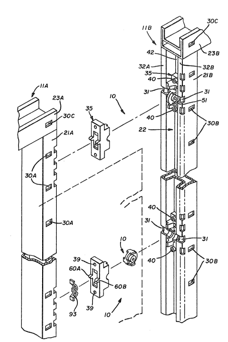
FIGS. 1 and 2 depict exploded perspectives of a representative pair of
linearly disposed wall panel assemblies 11A and 11B. The wall panel assemblies
11A and 11B have vertical frame members 21A and 21B on the opposed lateral
edges thereof Each vertical frame member 21 presents an outwardly facing,
vertically orieDted channel, or groove, 22 which preferably extends the full length
of each vertical frame member 21 The vertical frame members 21 in each wall
panel assembly 11 are secured to the top, or upper, horizontal frame members 23
as well as to the bottom, or lower, frame members 24 As best seen in FIG 1,
therefore, the *ame member 21A extends vertically between the upper, horizontal
frame member 23A and the lower, horizontal frame member 24B in wall panel
assembly 11A Similarly, the frame member 21B extends vertically between the
upper, horizontal frame member 23B and the lower, horizontal frame member 24B
in wall panel assembly 11B
It may also be desirable to utilize a horizontally disposed, medial
stringer 25 which extend between the vertical frame members 21. As such, a
stringer 2SA may extend horizontally between the vertical frame members 21A and
21C in wall panel assembly 11A, and a similar medial stringer 25B may be
employed in wall panel assembly 11B. The upper frame members 23, the lower
frame members 24 and the medial stringers 25 may, as depicted, all incorporate achannel-shaped race 26 which permits the convenient installation of electric andtelephone lines as well as computer communication cables.
~,f ~,~S J~ ,J ~ ~
-7-
Before con~inuing with a description of the interconnecting structure 10
it should be explained that each wall panel assembly 11 may be provided with oneor more foot and levPlling mechanisms 27 which are designed to establish7 and
maintain, the adjacenl wall panel assemblies 11 at a predeterrnined height above05 the floor, or the foot and levelling mechanisms 27 may be employed to establish
a level orientation for the overall wall, regardless of the irregularities of the
floor. A more detailed description of a representative foot and leveling
mechanism 27 can be found in co-pending United States Patent application, SerialNo. , also filed on June 12, 1~89, and assigned to the assignee
10 hereo
- A plurality of anchor slots 30 are spaced along selected structural
members, such as the vertical frame members 21 and the upper frame member 23,
which delineatc the lateral and upper edges of the wall panel assemblies 11. As
best seen in FIG. 2, a plurality of anchor slots 30A may be provided ;n the
vertical frame member 21A, a plurality of anchor slots 30B may be similarly
provided in vertical frame mernber 21B and comparable anchor slots 30C and 30D
may be provided in the upper frame members 23A and 23B, respectively, of the
wall panel assemblies 11A and 11B. The anchor slots 30 are adapted to secure
the decorative panel coverings to the wall panel assemblies 11 in a rnanner wellknown to the art. The panel coverings are generally a fabric covered sheet
which is removably secured to the frame. The fabric coverings may be added
after the panel assemblies are secured together to form the relocatable wall. The
fabric coverings can be changed after the wall is assembled for the purposes of
redecorating, all as is well known to the art.
Access slots 31 are provided at predetermined locations along the
length of each vertical frame rnember 21. The access slots 31 extend transversely
through the side flanges 32A and 32B -- which define the sides of the vertical
channels, or grooves, 22 -- to provide an opening through which an appropriate
tool, as hereinafter discussed, can be inserted. The purpose for the tool will also
be hereinafter explained in conjunction with the description relating to the
operation of the interconnecting structure 10.
The vertical channels 22 are adapted to receive one or more cam key
blocks 35, which are important components of the interconnecting structure 10.
Each cam key block 35, which can be seen in FIGS. 1 and 2, but which are rnost
clearly depicted in FIGS. 3, 4 and 5, has a main body portion 36 that is
substantially rectangular in shape with a pair of support pads 38A and 38B that
extend longi~udinally outwardly from the body portion 36. Each support pad 38
has an opening 39 through which a fastening means 40 may be insertably received
. . .
-8-
to secure the cam key blocks 35 within the ~roove 22 of each vertical frame
member 21. In the preferred embodiment the fastening means 40 may comprise
threaded devices which extends through the opening 39 in each support pad 38
threadably to engage the web portion 42 of the chaMel 2~. It should be
05 appreciated, however, that other securing devices, such as rivets, may be
employed to secure the cam key blocks 3S within the charmels 22 of the vertical
frame members 21.
The body portion 36 of each cam key block 35 has a longitudinal axis
43, a laterally transverse axis 44 and a normal axis 45 which is perpendicular to
0 the intersection of the longitudinal and the laterally transverse axes 43 and 44
A generally rectangular, central slot 46 -- which is elongate in the direction of
the longitudinal axis 43 and relatively narrow in the direction of the laterallytransverse axis 44 -- extends parallel to the normal axis 45 to penetrate the body
portion 36 of the cam key block 35. By penetrating the body portion 36 the
central slot 46 opens through the obverse face 48 as well as the reverse face 49of the body portion 36. The obverse face 48 lies in a plane which includes the
laterally transverse axis 44, and the reverse face 49 is disposed in a plane that is
parallel to, and displaced from, the obverse face 48. When the cam key block 35
is secured w~thin a channel 22 the reverse face 49 en~ages the web portion 4~ ofthe charmel 22.
A pair of serni-cylindrical bearing surfaces 50A and SOB are recessed
into the obverse face 48, and are disposed concentrically about the laterally
transverse axis 44. The recessed area that is partially surrounded by each
bearing surface S0 in the body portion 36 comprises an opening 51 to permit
access to the hereinafter described mechanism that is received within the central
- slot 46 and journalled on the bearing surfaces S0. As such, the purpose of the
access opening 51 will be more fully hereinafter described.
The opposite side walls 53A and 53B of the central slot 46 are
interrupted by a pair of substantially semi-annular ribs 54A and 54B. The radially
outer surfaces on the respective ribs 54A and 54B comprise cam surfaces 55A and
SSB, and the radially inner surfaces are registered, and merge, with the respective
semi-cylindrical bearing surfaces S0. Whereas the semi-cylindrical bearing
surfaces S0 may be centered about the laterally transverse axis 44, the cam
surfaces 55A and SSB, if arcuate, would be preferably centered about an axis 56
which also intersects the normal axis 45 but which is offset from the laterally
transverse axis 44 in the amount of a few thousandths of an inch, as representedat 58, in order to provide the necessary camming action from the surfaces SSA
and 55B, as will hereinafter be more fully explained. It will also become apparent
2 ~
that the cam surfaces 55A and 55B may be somewhat elliptical, as depicted, to
effect the desired result.
A pair of aligning protuberances 60A and 60B extend outward from the
reverse face 49 of the body portion 38. 1 he aligning protuberances 60 are
05 adapted to be received in one of the aligning slots 61 (FIG. 1) selected from the
plurali~ thereof which are provided at predetermined locations along the web wall
42 of ~he channel 22. The engagement of the aligning protuberances 60 within
the appropriate aligning slot 61 assures that each cam key bl~ck 35 is preciselydisposed at the desired vertical location within the channel 22 of each vertical10 frame member 21, as necessary to assure the proper interac~ion between the cam
key blocks 35 on opposed vertical frame members 21 of successively adjacent wall
panel assemblies 11, as well as wi~h the cam key blocks 35 on any post
arrangement 20 interposed between converging wall panel assemblies.
As depicted in FIC;S. 2 through 5, a pair of anchor recesses 62A and
15 62B may be provided in the reverse face 49 of each cam key block 35. The
recesses 62 are disposed, or o~herwise positioned, to accornrnodate the mountingtangs 63A and 63B, respectively, of the hereinafter more fully described spring
detent member 64 which is individually depicted in FIG. 1.
A pair of saw-tooth, lateral locators 65 and 66 are longitudinally
20 spaced, preferably at opposite ends of the obverse face 48. Each lateral locator
65 and 66 has a projecting, positioning lug 68 and a laterally adjacent positioning
recess 69. As most clearly represented in FIGS. 3-5, the lugs 68A and 68B in therespective lateral locators 65 and 66 are located on the same lateral side of the
longitudinal axis 43 but on longitudinally opposite sides of the laterally transverse
25 axis 44. In fact, the positioning lugs may we}l be located adjacent the longitudinal
ends of the central slot 46.
The positioning recesses 69A and 69B in the respective lateraI locators
65 and 66 are located on laterally opposite sides of the longitudinal axis 43 from
the lugs 68A and 68B and also on longitudinally opposite sides of the lateral axis
30 44. An inclined ramp 70A extends between the apex surface 71A of the
positioning lug 68A and the floor 72A of the laterally adjacent positioning recess
69A. Similarly, an inclined ramp 70B extends between the apex surface 71B of
the positioning lug 68B and the floor 72B of the laterally adjacent positioning
recess 69B. The dimensions of ~he lugs 68 and recesses 69 in each lateral locator
35 65 and 66 are chosen such that when a cam key block 35A is brought into
ablltting engagement with an opposed cam key block 35B, as depicted in FIG. 8,
the positioning lugs 68 on cam key block 35A will bc snugly received within the
opposed positioning recesses 69 in carn key block 35B, with the inclined ramps 70
~lo~
on the opposed cam key blocks 35A and 35B Iying in contiguous juxtaposition
Similarly, the laterally outwardly disposed sid~ walls 73A and 73B on each
positioning lug 68A and 68B will be engaged with the oppositely facing, laterally
outwardly disposed side walls 74A and 74B of the positioning recesses 69A and
05 69B within which the lugs 68A and 68B are received
As such, the various surfaces of the lateral locators 65 and 66 effect,
and maintain, lateral alignment beh~een opposedly interfitted cam key blocks 35
Specifically, the configuration of the lateral locators 65 and 66 permits the lateral
locators 65 and 66 on opposed cam key blocks 35 to interfit in such a way as lo
guide opposed cam key blocks 35 into an aligned disposition and to secure the
interfitting cam key blocks 35 in îheir aligned disposition Hence, when the
opposed cam key blocks 35A and 35B are secured to successively adjacent wall
panel assemblies 11A and 11B, as depicted in FIG 8, and when those wall panel
assemblies are brought together in a linear intersection 12, as depicted in FIG 15,
the lateral locators 65 and 66 on the opposed, interfitting cam key blocks 35 will
secure the wall panel assemblies 11A and 11B against undesired lateral
displacement
FIGS. 6 and 7 depict a representative cam key 75 that is adapted to
secure opposedly aligned, and interfitted, cam key blocks 35 not only against
longitudinal separation but also to bring, and maintain, the obverse faces 49 onthe opposed cam key blocks 35 into firm engagement. As seen in FIGS 1, 6 and
7, the cam key 75 has a central hub portion 76 which serves as a journal A
disk portion 78 extends radially outwardly from the axially medial portion of the
hub 76 The disk portion 78 has a cylindrical outer surface 79, and a plurality of
locking bolts extend axially outwardly from the disk portion 78, preferably in
proximity to the cylindrical outer surface 79 thereof First and second pairs of
locking bolts 80 and 81, respectively, extend axially outwardly from the disk
por~ion 78 in diametric opposition, and a pair of retaining bolts 82 is located at
substantially 90 (FIG 6) from both the first and second pairs of locking bolts 80
and 81 As such, there is an approximately 180 span along the circurnference of
the disk portion 78 which has no bolts, either locking or retaining
Each pair of locking bolts 80 and 81, as well as the pair of retaining
bolts 82, may have an outer, cylindrical surface which merges with, and i5 a part
of, the cylindrical surface 79 on the disk portion 78 The pairs of locking bolts80 and 81 have radially inner, locking surfaces 84 and 85, respectively. The
locking surfaces 84 and 85 are preferably planar, as depic~ed in FIG 6, and/or
the reason for using planar locking surfaces 84 and 85 will be hereinafter more
r~3 ~J i~
fully explained. The engaging surfaces 86 on the pair of retaining bolts 82 may,however, be arcuate, also as depicted in FIG. 6.
A tool engaging aperture 88 is provided in at least one of the end
walls 8~ and 90 on the central hub portion 76, and, as shown, the aperture 88
05 may extend axially through the central hub 76. The tool engaging aperture 88 is
shown as being hexagonal to accept a tool such as a hex-wrench or Allen wrench.
If desired, however, the tool engaging aperture 8g could well be slottecl to accept
the blade of a standard screwdriverO In either event, acceptance cf a tool within
the tool engaging aperture 88 perrnits the cam key 75 to be selectively rotated, the necessi~y for which will hereinafter become more apparent.
FIG. 8 represents the interfitting engagement of two opposed cam key
blocl~s 35A and 35B that are respectively secured to successively adjacent wall
panel assemblies 11A and 11B in a linear intersection 12, as depicted in FIG. 15.
Each cam key block 35 is secured within the vertical groove 22 of the opposed
vertical frame members ~1 in successively adjacent wall panel assemblies 11A andllB by fastening means 40. It will be noted that when the cam key blocks are so
secured, a spring detent rnember 64 is generally captured between the reverse face
49 on the body portion 36 of each cam key block 35 and the web portion 42 of
the channel 22 within which the cam key block 35 is secured. Specifically, the
mounting tangs 63 of the spring detent member 64 are received within the
recesses 62, and the body portion 91 of the spring detent member 64 which
extends between the tangs 63 bows outwardly and into the central slot 46 of the
cam key block 35 which has so captured the spring detent member 64. A detent
recess 92 is disposed medially of the bowed body portion 91 rele sably to engage
the locking bolts 80 and 81 or, alternatively, as will be hereinafter explained, the
retaining bolts 82. It shou~d be noted that in order to engage the bolts 80 and
81, or 82, it is necessary for the bowed body portion 91 to be notched, as at 93(FIG. 2), to preclude the cylindrical outer surface 79 on the disX portion 78 from
preventing engagement between the detent recess 92 and the desired bolt 80, 81
or 82.
The cam key 75 is disposed within the central slots 46 of the opposed
cam key blocks 35A and 35B such that the planar locking sur~aces 84 and 85 on
the first and second pairs of locking bolts 80 and 81, respectively, engage the
cam surfaces 55 on the ribs 54 which extend into the central slots 46 of the
opposed cam key blocks 35A and 35B. That is, the pair of locking bolts 80
engage the cam surface 55 associated with the cam key block 35A secured to wall
panel assembly 11A, and the pair of locking bol~s 81 engage the cam surface 55
associated with the cam key block 35B secured to wall panel assembly 11B. The
~ ~ ~ r~; ''3
-12-
retaining surfaces 86 on the pair of retaining bolts 82 serve no present purposeand are, therefore, disposed to be substantially centrally aligned on the
concurrent longitudinal axes 43 of the conjoined cam key bloc~s 35.
l he planar locking surfaces 84 and 85 are disposed substantially
05 tangential to the cam surfaces 55, and as previously notéd, the dimensions and/or
con~lguration of the cam surfaces 55 are such as to perrni~ ~he planar locking
surfaces 84 and 85 to draw the two, successively adjacent wall panel assemblies
11A and 11B into firm end-to-end engagement. The arcuate surface 86 need not
firmly engage the cam surfaces 55, and the surface 86 may, therefore, have an
lo arcuate dimension that is somewhat larger that the arcuate dimension of the cam
surfaces 55.
As should now be understood, two opposedly aligned, and interfitted,
cam key blocks 35A and 35B are held firmly together by a cam key 75. The use
of four cam key blocks 35 located in vertically spaced pairs are generally
sufficient to secure a linear intersection 12 for most reasonable wall heights.
To secure, or release~ successively adjacent wall panel assemblies 11 by
use of the interconnecting structure 10 is a straight forward operation. For
example, to begin with the release operation one can continue to refer to FIG. ~,
and it will be observed that a workman need only insert a tool (not shown)
having the appropriate configuration between the decorative pane]s coverings 97Aand 97B which are rnounted ~o, and are a part of, the respective wall panel
assemblies 11A and 11B. lhe tool can pass inlo the access opening 51 (Fl&S. 2
and 3) provided between ~he abutting cam key blocks 35A and 35B to engage the
mating configuration of the aperture 88. Thereafter rotation of the tool through9û (in either direction) forces the pair of locking bolts 80 to overcome the
pressure applied by the detent recess 92 in the bowed body portion 91 of the
spring detent member 64 held by cam key block 35A. At the same time the
rotative force causes the locking bolts 81 similarly to overcome the pressure
applied by the detent recess 92 in the spring detent member 64 held by the carn
key block 35B. After the cam key 75 has been rotated through 90 the retaining
bolts g2 snap into the detent recess 92 associated with one of the cam key blocks
35A or 35B. This engagement o~ the retaining bolt 82 with the detent recess 92
provides the workman with both a tactile indication (a sudden release of the
rotative force followed immediately by an increase in the rotative resistance~ and
an aural indication, as the spring detent member 64 snaps the detent recess 92
into engagement with the pair of retaining bolts 82. When all the interconnecting
structures 10 which secured the two successively adjacent wall panel assemblies
11A and 11E~ togcther have been thus released, the wall panel assemblies 11A and
r~
-13~
11B can be translated linearly apart ~o release the two cam key blocks 35A and
35B.
Each cam key 75 will remain within only one of the cam key blocks 35
-- VLZ., that cam key block 35 whiGh is engaged by the retaining bolts 82.
05 Because approximately 180 of the cylindrical outer surface 79 on the cam key 75
opposite the retaining bolt 82 has no locking, or retaining, bolt, there is nothing
to restrict separation of the cam key blocks 35 in the direction of ~he normal
axis 45. This separation of the opposed cam key blocks 35 is further assured by
~irtue of the fact that the locking surfaces 84 and 85 are planar, and tangential
to the cam surface 55. As such, there is no restraining interaction between the
cam key blocks 35, and the cam key 75, to preclude the desired separation.
EYen after the cam key blocks 35A and 35B are fLIlly separated, the
cam key 75 will remain secured within one of the cam key bloclcs 35, unless one
rotates the cam key 75 through 180 after the cam key blocks 3S have been
separated. Such rolation of the cam key 75 would position the retaining bolts 82exteriorly of the cam key block 35 and position the locking bolts 80 and 81 suchthat they can be translated past the ribs 54, out of engagement with the cam
surfaces 55. Of ~course, simply leaving the cam key 75 in situ may facilitate the
joinder of that wall panel assembly to a successive wall panel assembly.
Effecting a joinder of a wall panel assembly 11B to another wall panel
assembly 11A in a linear intersection 12 is simply accomplished be reversing theprocedure previously explained to separate the wall panel assemblies 11A and 11Bfrom the intersection 12. Joinder, however, cam be more readily accomplished by
including certain dimensional, or space, tolerances which tend to facilitate
insertion of the cam key 75 -- which has already been received in one cam key
block 35 -- into the central slot 76 of the opposed cam key block 35. The ~ost
difficult aspect Of inserting the cam key 75 is to have the pairs Of locking bolts
80 and 81 enter the central slot 76. This difficul~ is compounded when there
are two, vertically spaced, opposed pairs of cam key blocks 35 into which two
cam keys 75 must be simultaneously inserted. It has been found, however, that
such difficulty can be obviated by utilizing two structural accommodations -~ viz:
(1) make the locking surfaces 84 and 85 planar, which, in conjunction with the
use of an elliptic configuration for the cam surfaces 55 provides clearance
between the radially inner locking surfaces 84 and 85 and the termini 94A and
94B of ~he rib S5A and the termini 95A and 95B of the rib 55B along which the
cam surfaces 55 are presented; and, (2) extending the dimension of the central
slot 46 along the longitudinal axis 43 to provide a modest clearance between the
-14-
cylindrical outer surface 79 on the carn key 79 and the longitudinal end walls 96
and 98 ~FIG. 4) of the central slot 76.
There are, o~ course, a number of ways in which ths~ dimensional
clearances can be increa~ed, or enlarged, to provide ~he desired result. As an
05 alternative to increasing the overall longitudinal dimens,ion of the central slot 76,
for example, one might provide a rectangular entry step in the end walls 96 ànd
98 of the central slot 76, or the end walls 96 and 98 can be formed to provide an
obliquely flared opening through the obverse face 48. What should be appreciatedat this point is that the size of the central slot 76 which opens through the
obverse face 48 affects the ease with which the adjacent panels can be joined
without undue hardship. However, there is no reason, or advantage, to make the
opening larger than necessary.
In any event, once the cam keys 75 have been received within the
central slots 76 of the opposed cam key blocks 35A and 35B, and the obverse face48 on each are abuttingly opposed, the cam keys 75 ~re rotated 90 in either
direction to achieve the position depicted in FIG. 8. Here, too, the engagement
of the pairs of loclcing bolts 80 and 81 within the detent recesses 92 will provide
the same tactile and aural signal that the wall panel assemblies have been
secured, one to the other, through the interconnecting structure 10 in an aligned
intersection 12.
To provide an L-intersection 13, a T-intersection 14 or an X-
intersection 15, one preferably utilizes a post arrangernent 20. The pertinent
details of a post arrangement 20 are best seen in FIG. 9, with a sub-assembly
depicted in FIG. 10. Each post arrangement 20 will also provide the desired
vertically space(l disposition of the cam key blocks 35 heretofore discussed with
respect to the linear intersection 12. However, in order to achieve a connectionbetween converging wall panel assemblies, as distinct from successively adjacent,
linearly disposed, wall panel assemblies, the converging wall panel assemblies are
each secured to a post arrangement 20 by virtue of the novel interconnecting
structure 10, and in the same manner as previously discussed with respect to thelinear intersection 12.
With respect to the structural details of each post arrangement 20,
then, a [air of unique structural components have been provided to secure the
requisite number of cam key blocks 35 to the typical square post member 100
utilized in each post arrangement 20. As seen in FIG. 9, each post member 100
has between two and four cam key blocks 35 secured thereto at each
predetermined, vertical level. ~s should bc apparent from FIGS. 9 and 11 through13, the number of sets of cam key blocks 35 installed on each post member 100 is
~ U .,~~s. 1, ~ S "~ ~
~15-
determined by the nurnber of wall panels assemblies 11 converging on the
resulting post arrangement 20. The necessary cam key blocks 35 are secured to
the post member 100 by fasteners, such as those previously identified by the
numeral 40 (not depicted in FIGS. ~ or 10, but their locations are hereinafter
05 described in considerable detail) in a manner similar to that used to secure the
cam key blocks 35 into the groove 22 of the vertical frame member 21. ~n
addition, however, each cam key block 35 is surrounded by a gusset assembly 101
such as that shown in FIG. 10.
Each gusset assembly 101 preferably employs a U-shaped bracket 102.
0 Each U-shaped bracket 102 has one full face 103 and two, halE-sides, or arrns, 104
and 105. The full face 103 has a rectangular aperture 106 and two circular
apertures 108A and 108B. The rectangular aperture 106 circumscribes tha~ portionof the body 36 on a cam key block 35 which extends outwardly of the support
pads 38, and the circular apcrtures 108A and 108B register with the openings 39
15 through the two support pads 38 on the cam key block 35.
The half-sides, or arms, 104 and 105 extend substantially
perpendicularly outwardly from the lateral edges of ~he full face 103. The arm
104 terminates in a rectangular recess 109A and two senu~circular recesses 110A
and 110B. Similarly; the arm 105 terminates in a rectangular recess 109B and
20 two, semi-circular recesses 111A and 111B. As can be readily observed, the
rectangular recesses 109A and 109B each comprise one half of a rectangular
aperture similar to that specifically identified at 106 in the full face 103, and the
semi-circular recesses 110 and 111 each comprise one half of the corresponding
circular apertures 108A and 108B.
Accordingly, when two gusset assemblies 101A and 101B are mounted in
opposition about a square post member 100 (FIG. 9), the opposing side arms 104A
and 104B as well as 105A and 105B complement each other to duplicate full faces
103. Hence, the two gusset assemblies 101A and 101E~ provide an identically
configured, and disposed, rectangular aperture and circular apertures on all four
30 sides of the resulting post arrangement 20. As such, a cam key block 35 can be
secured on each side of the post arrangement 20 by the use of fasteners which
pass through the circular apertures in the appropriate gusset assembly 101 and the
registered openings 39 through the support pads 38 in order to anchor the cam
key blocks 35, and the gusset assemblies 101 which embrace the cam key blocks
35, to the s~uare post rnember 100.
A pair of spacer brackets 112A and 112B are included in each gusset
assembly 101 and are dispo~ed, one on either sidc of each rectangular aperture
105, a third spacer bracket 112C is secured to the side arm 104, adjacent the
, . .
2 ~ r~ l
-16-
rectangular recess 109A therein, and a fourth spacer bracket 112D is secured to
the side arm 105, adjacent ~he recess 109B therein. Thc spacer brackets 112 all
present a raised surface 113, each raised surface 113 simulating one of the sideflanges 32 in the vertical frame members 21. Eaeh spacer bracket 112 also
05 incorporates an offset recess 114 which simulates one of the access slots 31 in
each side flange 32. The spacer brackets 112 may be tack welded, or otherwise
secured, to the U-shaped bracket 102 of the appropriate ~sset assembly 101.
Tack welding may be conveniently accomplished where the mounting tabs 115 and
116 at each end of the spacer bracket 112 engage the full face 103 of the
lo bracket 102 in gusset assembly 101 as well as where the offset recess 114
engages the bracket 102.
FICiS. 11 through 13 represent the three most comrnon uses for the
post arrangement 20. FIG. 11 represents a two panel corner configuration,
sometimes identified as an ~intersection 13. ln an I~intersection 13 the post
arrangement 20A has hvo wall panel assemblies 11C and 11D secured thereto in a
manner similar lo that described in conjunction with FIG. 8. That is, a cam key
(not shown) is used to secure the cam key blocks 35S: and 35D on the converging
wall panel assemblies 11C and 11D to the opposing cam key ~lock 35E and 35F on
the post arrangement 20A.
,4s explained in conjunction with the joinder of two successively
adjacent wall panel assemblies 11A and 11B ~FIG. 8) the use of cam key blocks 35at t~,vo vertically space locations is generally all that is required to effect a most
satisfactory joinder. Similarly, the same number is all that should normally be
required to secure converging wall panel assemblies together through the
intercession of a post arrangement 20.
At those locations about the periphery of the post arrangement 20A
where no cam key blocks need be employed, because no wall panel assemblies are
present, a ~ap may be installed to provide a decorative cover. In the L,
intersection 13 a two-wall cap 116 is used to cover the spacer brackets 112 on
the two otherwise exposed surfaces of the post arrangement 20. A pair of
rectangular filler blocks 118 may be employed with tbe two-wall cap 116. The
filler blocks have outer end dimensions substantially equal to the support pads 38
to prevent the fasteners from causing the gusset assemblies 101 to collapse. If
desired, the filler blocks 1l~ may be provided with a central pillar portion 11~which has a dimension substantially equal to the height of the spacer brackets
112 to assist in supporting the two-wall cap 116. As should now be apparent, thetwo-wall C;lp 116 is installed to provide a decorative cover over those spacer
brackets 112 which do not surround a cam key block 35. The two-wall cap 116
,
-17- 2 ~ ~r~
may have a plurality of fingers 120 along each lateral edge which are received
within the edge slots 121 provided along the outer edges of the side flanges 32 of
the vertical frame members 21.
The post arrangement 20B shown in FIG. 12, provides for a three
os panel, T-intersection 14. In a T-intersection 14 the post arrangement 20B has
three wall panel assemblies 11E, llF and llG secured thereto~ also in a manner
similar to that described in conjunction with FIG. 8. That is, a cam key (not
shown) is used to secure the cam key blocks 35E, 35F and 35G on the converging
wall panel assemblies 11E, 11F and 11G to the opposing cam key block 35H, 35J
lo and 35K on the post arrangement 20B. In the T-intersection arrangement 14, only
one filler block 118 need be used. This filler block 118 is covered by a
decorative one-wall cap 122. In this configuration the one-wall cap 122 is also
provided with fingers 120 along each lateral edge which are received within the
edge slots 121 provided along the outer edges of the side flanges 32 ~f the
vertical frame members 21.
The post arrangement 20C shown in Fl~. 13, provides for a four panel,
X-intersection 15. In an X-intersection 15 the post arrangement 20C has four
wall panel assemblies 11B, 11H, 11J and 11K secured thereto, also in a manner
similar to that described in conjunction with FIG. 8. That is, a cam key (not
shown) is used to secure the cam key blocks 35L, 35M, 35N and 35P on the
converging wall panel assemblies 11B, 11H, 11J and 11K to the opposing cam key
blocks 35Q, 35R, 35S and 35T on the post arrangement 20C. In the X-intersection
arrangement 15 no filler blocks 118 nor caps are required inasmuch as a wall
pane assembly is attached to all sides of the post arrangement 20C.
FIG. 14 depicts an alternative arrangement for a cam key block,
identified generally by the numeral 125. The cam key block 35 heretofore
described in conjunction with FIGS. 3-5 is preferably a sintered metal part. Such
parts can be rnade wiih considerable strength while the dimensions of the part
can be held close such that machining is not required. The alternative
embodimen~ of a cam key block 125 is a stamped metal part which can generally
be made for less cost.
The alternative form of the cam key block 125 has a body portion 126,
and a pair of support pads 128A and 128B extend longitudinally outwardly from
the body portion 126. Each support pad 128 has an opening 129 through which a
fastener means (not shown) may be insertably received to secured the cam key
block 125 in the selected location. The body portion 12b has a longitudinal axis130, a laterally transverse ~xis 131 and a normal axis 132.
- ~ 8~ r~
The body portion 126 includes a pair of legs 133A and 133B which are
disposed parallel to the normal axis 13Z and which extend upwardly frorn the
suppor~ pads 128A and 128B, respectivcly, to merge with a bridge portion 135
which spans between the upper extremities of the legs 133A and 133B. The
05 bridge portion 135 lies substantially within the plane defined by the longitudinal
and the laterally transverse axes 130 and 131~
The medial portion of ~he bridge portion 135 has a substantially semi-
cylindrical deflection 136 which is generally concentric about the laterally
transverse axis 131~ A central slot 138, which is elongate in the direction of the
0 longitudinal axis 130 but relatively narrow in the direction of the laterally
transverse axis 131, penetrates the deflection 136 and that. part of the bridge
portion 135 longitudinally adjacent the deflection 136. The longitudinal ends ofthe central slot 138 are defined by cross slots 139 and 140 which are elongate in
the direction of the laterally transverse axis 131.
By thus bifurcating at least the deflection 136, a pair of parallel,
generally semi-annular ribs 141A and 141B are formed. The substantially semi-
cylindrical faces of the ribs 141 comprise concave bearing surfaces 142, and theconvex faces of the ribs 141 comprise cam surfaces 143. It will be noted that the
ribs 141 need not be exactly semi-annular; a slightly elliptical configuration to the
ribs 141 will not defeat their ability ~o allow the central hub 76 of the cam key
75 to be journalled on the concave bearing surfaces 142 and yet will permit the
cam surfaces 143 to perform their function of forcing the locking bolts 80 and 81
to draw the opposed cam key blocks 125 into locking engagement.
Accordingly, a cam key 75 can be insertably received within the central
slot 138. The locking, and/or the retaining, bolts 80, 81 or 82 on the cam key
75 can pass through the cross slots 139 and 140 to permit the central hub 76 to
be rotatably journalled on the bearing surfaces 142 and to permit the planar
locking surfaces 84 and 85 on the locking bolts 80 and 81, as well as the arcuate
retaining surface 86 on the retaining bolts B2, to engage the cam surfaces 143
on the ribs 141.
The body portion 126 also presents lateral locators 145 and 146. As
depicted, the lateral locator 145 comprises a tab 148 that is struck from the
bridge portion 135 to extend substantially perpendicularly outwardly with respect
to the bridge por~ion 135, leaving an opening 149. ~he lateral locator 146
comprises a tab 150 that is struck from the bridge portlon 135 to extend
suhstantially perpendicularly inwardly with respect to the bridge portion 135,
leaving an opening 151. 'rhe tab 148 in the first lateral locator 145 and the
opening 151 in the second lateral locator 146 are positioned such that when two
-lg-
of the cam key blocks 125 are uscd in as an opposed pair, the tabs 148 will be
aligned wi~h the openings lS1. In such a situation the tabs 14g in the lateral
locators 145 will be located in longitudinally adjacent juxtaposition with the tabs
1S0 in the lateral locators 146.
05 A further variation of the fundamental cam key block is the end cap
clip, identified generally by the numeral 155 in FIG. 1, to sesure a decorative end
cap 156 to a wall panel assembly 11. The c!ip 155 has a virtually planar body
portion 158 with a pair of modestly offset support pads 159A and 159B extending
longitudinally outwardly from the body portion 158. Each support pad 159 may
have an opening 157 through which a fastener means 40 may be insertably
received to secure the clips 155 at selected locations along the decorative end cap
156. Or, the astener means 40 may be received in the back of the decorative
end cap 156, with the head portion of the fastener means 40 overlying the pads
159 to hold the clip 155 in place.
The body portion 158 has a shallow V-notch 160 which is generally
centered along the longitudinal extent of the body portion 158. A elongate
central slot 161 penetrates the V-notch 160 and that part of ~he body portion
158 longitudinally adjacent the V-notch 160. The longitudinal ends of the central
slot 161 are defined by cross slots 162 and 163. By thus bifurcating at least the
V-notch 160, a pair of parallel, V-shaped ribs 165A and 165B are formed. The
faces on either side of the interior angle of the ribs 165 comprise bearing
surfaces 166, and the faces on either side of the exterior angle of the ribs 165comprise cam surfaces 168. It will be understood that the central hub 76 of the
cam key 75 rotatably engages the bearing surfaces 166 so that the cam surfaces
2s 168 force the locking bolts 80 and 81 to draw the cam key block 155 into
abutment with an opposed cam key block 35 mounted on the vertical ~rame
member 21 of a wall panel assembly 11, thereby providing a convenient adaptationof the present invention for mounting the decorative end cap 156.
It should be understood that the cam key block 35 allows the user to
effect selective connection between successive wall panel assemblies 11. That is,
the orientation of the cam key blocX 35 on the frame member 21 will determine
whether or not an opposed cam key block 35 will properly mate to effect a
joinder between successive wall panel assemblies 11. This result obtains becausethe lateral locators 65 and 66 are both on the same side of the longitudinal axis
43. Hence, by simply effecting an appropriate top-to-bottorn disposition of the
cam key blocks 35 one can predetermine which lateral edges can be matingly
engaged and which cannot. Thus, should one wish to be certain that only
selected lateral edges on any two wall panel assemblies be capable of joinder, the
20-
appropria~e top-to-bottom disposition of the am kcy blocks will cause the
projecting lugs 68 on the cam key block 35 secured to one wall panel assembly tomate wi~h the lateral recesses 69 on the cam key block 35 in the opposed wall
panel assembly 11, but a simple top-~o-bottom inversion of one cam key block 35
05 will locate the projecting lugs 68 on the opposed cam lcey blocks 35 in such a
disposition that they cannot matingly engage the recesses 69 on the opposed cam
key block 35; rather, the projecting lugs 68 will abut each other and thereby
preclude joinder.
On the other hand, should one wish to accommodate universality so
that opposing cam key blocks will matingly engage without regard to their top-to-
bottom disposition on the opposed wall panel assemblies, the cam key blocks can
incorporate the configl~ration identified by ihe numeral 235 in FI(:~. 18.
The only difference ~etween the alternative form of the cam key blocks
35 and 235 relates to the disposition of the saw tooth lateral locators 265 and
266. Hence, all components of the cam key block 235 which are identical to the
cam key block 35 will be identified in FIG. 18 with the same n umeral used to
identify those same parts on cam key block 35. To the contraly, all par~s that
are different, or differently disposed, will be prefixed by the numeral "2".
With reference, then, to FIG. 18 the body portion 36 of each cam key
block 235 has a longitudinal axis 43, a laterally transverse axis 44 and a norrnal
axis 45 which is perpendicular to the intersection of the longitudinal and the
laterally transverse axes 43 and 44. A generally rectangular, central slot 46--
which is elongate in the direction of the longitudinal axis 43 and relatively
narrow in the direction of the laterally transverse axis 44 -- extends parallel to
the normal axis 45 to penetrate the body portion 36 of the cam key block 235.
By penetrating the body portion 36 the central slot 46 opens through the obverseface 48 as well as the reverse face 49 of the body portion 36. The obverse face
48 lies ;n a plane which includes the laterally transverse axis 44, and the reverse
face 49 is disposed in a plane that is parallel to, and displaced from, the obverse
face 48. When the cam key block 235 is secured within a channel 22 the reverse
face 49 engages the web portion 42 of the channel 22.
A pair of saw-tooth, lateral locators 265 and 266 are longitudinally
spaced, preferably at opposite ends of the obverse face 48. Each lateral locator265 and 266 has a projecting, positioning lug 268 and a laterally adjacent
positioning recess 269. As represented in FIG. 18, the lugs 268A and 268B in therespective lateral locators 265 and 266 are located on opposite sides of the
longitudinal axis 43 as well as on longitudinally opposite sides of the laterally
-21-
transverse axis 44. ~lere, too, the positioning lugs 268A and 268B may well be
located adjacent the longitudinal ends of the central slot 46.
~e positioning recesses 269A and 269B in the respective lateral
locators 265 and 266 are located on laterally opposite sides of the longitudinal05 axis 43 from the lugs 268A and 268R and therefor also on laterally opposite sides
of the longitudinal axis 43 from each other. As with the positioning lu~gs 268A
and 268B, the positioning recesses 269A and 269B are on longitudinally opposite
sides of the lateral axis 44.
An inclined ramp 270A extends bet veen the apex surface 271A of the
positioning lug 268A and the floor 272A of the laterally adjacent positioning
recess 269~. Similarly, an inclined ramp 270B extends bet Iveen the apex surface271B of the positioning l.lg 268B and the floor 272B of the laterally adjacent
positioning recess 26gB. The dimensions of the lugs 268 and recesses 269 in eachlateral locator 265 and 266 are chosen such that when cam key blocks 235 are
brought into abutting engagement, the positioning lugs 268 on each cam key block235 will be snugly received within the opposed positioning recesses 269 in the
opposed cam key block 235, with the inclined ramps 270 on the opposed cam key
bloclcs 235 Iying in contiguous juxtaposition. Similarly, the laterally outwardly
disposed side walls 273A and 273B on each positioning lug 268A and 268B will be
engaged with the oppositely facing, laterally outwardly disposed side walls 274Aand 274B of the positioning recesses 269A and 26gB within which the lugs 268A
and 268B are received.
As such, the various surfaces of the lateral locators 265 and 266 effect,
and maintain, lateral alignment between opposedly interfitted cam key blocks 235.
Specifically, the configuration of the lateral locators 265 and 266 permits the
lateral locators 265 and 266 on opposed cam key blocks 235 to interfit in such away as to guide opposed cam key blocks 235 into an aligned disposition and to
secure the interfitting cam key blocks 235 in their aligned disposition, irrespective
of the top-to-bottom disposition of the cam key blocks 235. Hence, when opposed
cam key blocks 235 are secured to successively adjacent wall panel assemblies 11,
and when those wall panel assemblies are brought together in a linear intersection
12, the lateral locators 265 and 266 on the opposed, interfitting cam key blocks235 will secure the wall panel assemblies 11 against undesired lateral displacement.
Obviously many modifications and variations of the present invention
are possible in light of the forgoing description. As should, therefore, now be
apparent, the present invention not only teaches that an interconnecting stmcture
which embodies the concepts of the present invention not only accomplishes
~ ~ A
-22-
structural integrity to the wall panel assemblies connected thereby but also
otherwise accomplishes the remaining objects of the invention.
",`: ` ` ,: ' : :' -
~ ~;
~ '