Note: Descriptions are shown in the official language in which they were submitted.
A ~S~CING TOOL AND A MASKING METiiIOD
BACKGROUND OF ~HE INV~:NTION
The present invention relates to a masking tool
employed to protect the hole(s) in an article such as
a car body from a surface treatment such as coating,
plating, vacuum evaporation, phosphatizing, and the
like.
Further, the present invention relates to a masking
method employing said masking tool to protect said
hole(s) of said article from said surface treatment.
More particularly, the present invention relates
to a masking member which comprises a cylinder having
an inlet at one end and an outlet at tha other end,
a plural number of masking members having a plug shape
respectively and these being put in said cylinder to
be placed one upon another, and a transporting means
arranged in said cylinder to transport said masking
members successively from the inlet to the outlet of
said cylinder.
To protect the hole(s) of said article, said masking
members in said cylinder of said maskin~ tool are
successively transported from the inlet to the outlet
of said cylinder by said transporting means and said
masking members are successively inserted in to said
holes of said article before said surface treatment.
When a surface treatment is effected on the surface
of an article, and if said article has hole(s) in which
said surface treatment should not be effected, said
hole(s) of said article should be protected by inserting
a masking member(s) havinq a plug shape into said hole(s)
before said surface treatment. In the case of the under
.
,
2`~
side of a car body, said hole(s) may be water ejecting
hole(s), shaft hole(s), harness hole(s) and the like,
and a paint such as a polyvinylchloride-sol, a tar-
urethane mixture and the like is coated on said underside
of said car body for corrosion, sound, and vibration
proofing.
In a case of the surface treatment of the article
having many holes, such as the coating of the under
side of a car body as above described, many masking
members should be inserted into said holes before said
surface treatment. Further, in the case of a continuous
mass-production line, said masking members should be
inserted into said holes in a short time. Still further~
in a case of a continuous mass-production line, it is
desirable that said masking members be automatically
inserted into said holes.
DESCRIPTION OF THE PRIOR ART
Hitherto, a masking member having a plugshape has
been provided to protect the hole(s) in an article.
Said masking member is made of a foamed plastic such
as a foamed polystyrene and the like (USSN 276,407).
Nevertheless, said mas~ing member(s) is(are) inserte~
into said hole(s) of said article by hand and much labor
and time have been necessary to protect said holes before
said surface treatment.
' ' ~ .
,
: .
SUMMARY OF THE INVENTION
Accordingly, an object of the present invention
is to save labor and time in the case of a masking
process before a surface treatment.
Another object of the present invention is to
provide a masking method suitable for automatic operation
A further object of the present invention is to
provide a masking method suitable for a continuous mass-
production line.
According to the present invention, there is
provided a masking tool employed to protect the hole(s)
of an article from a surface treatment, which comprises
a cylinder having an inlet at one end and an outlet
at the other end thereof, a plural number of masking
members having a plug shape respectively and being put
in said cylinder to be placed one upon another, and
a transporting means arranged in c;aid cylinder to trans~
port said masking member from the inlet to the outlet
of said cylinder and a masking method for the hole(s)
of an article by empIoying said masking tool which
comprises transporting said masking members in said
cylinder from the inlet to the outlet thereof by said
transporting means and inserting said masking members
into hole(s) of an article one by one.
B}~IEF DESCRIPTION OF T~E DgANINGS
Fig.1 to Fig.4 relate to a first embodiment of
the present invention.
Fig.1 is a side sectional view of a masking tool.
Fig.2 is a perspective view of a masking member.
Fig.3 is a side sectional view of the hole of an artecle
into which said masking member is inserted.
--3--
;` ' :
8~.
Fig.~ is a side sectional view of the hole of an article
after a coating.
Fig.5 relates to a second embodiment of the present
invention and a side sectional view of a mas~ing tool.
DETAILED DESCRIPTION
Fig.1 to Fig.4 relate to a first embodiment of
the present invention. Referring no~7 to Fig.1 to Fig.4,
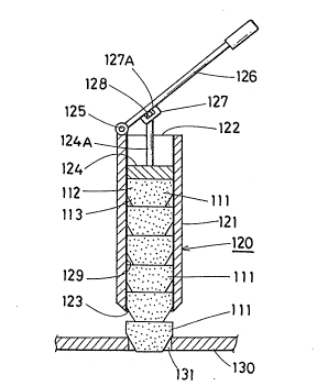
a masking tool(120) comprises a cylinder(121) having
an inlet(122) at one end and an outlet(123) at the other
end, a friction sheet(129) attached to the inside of
said cylinder(121), a plural number of masking members
(111) put in said cylinder(121) to be placed one upon
another, and a piston(124) as a transporting means.
Said piston(124) is inserted into said cylinder(121)
from said inlet(122) thereof and a handle(126) which
is notably attached on said inlet(122) by an axis(125)
is connected to the piston rod(124A) of said piston
wherein a pin(128) of said piston rod(124A) is inserted
in a groove(11~A) of a bracket(127) of said handle(126).
As shown in Fig.2, each masking member(111) has a
plug shape and is made of a material, such as of plastics
or a rubber such as polystyrene, polyethylene, polypropy-
lene, ethylene-propylene copolymer, polyvinylchloride,
polyvinylidene chloride, polymethacrylate, styrene-butad-
iene copolymer acrylonitrile-butadiene copolymer, poly-
butadine polyisoprene, ~olyisobutylene, polychloroprene,
isoprene-isobutylene copolymer, natural rubber, poly-
urethane, melamine resin, urea resin, phenol resin,
epoxy resin and the like; foams of said plastics or
said rubber; mixture of said plastics of said rubber
with a filler such as a calcium carbonate, a talc, a
bentonite, a fly ash, a blast furnace slag, and the
like, a fiber material such as a thermoplastic resin
L7~
- impregnated fiber a thermosettlng risen - impregnated
fiber; wooden material such as wood, hardboard, plywood
and the like; metal material and the like; composite
material consisting of a plural number of materials
selected from the group of said materials.
A plural number of said masking members(111) are
placed one upon another as above described and if desired,
said ` masking members( 111 ~ be attached respectively
by an adhesive or by melting.
A plural number of said masking members( 111 ) in
said cylinder(121) of said masking tool(120) are successi-
vely transported from the inlet(122) to the outlet(123)
by operation of said piston(124) by said handle(126)
and said masking members(111) are inserted into holes
(131) in an article(130) one by one as shown in Fig.3,
and after this, a paint such as a polyvinylchloride-
sol, an urethane resin, an asphalt, a rubber-asphalt
mixture, a tar-urethane mixture and the like is coated
on the surface of said article to form a coa~ing layer
(140) as shown in Fig.3. After coating said masking
member(111) is removed from sai~ hole(131) and as shown
in Fig.4, said coating layer(140) is not formed on the
inside of said hole(131).
If desired, said masking tool(120) is operated
by a robot, and in this case, said masking members(111)
are automatically inserted into said hole(s)(131) without
the necessity of a laborer's hands.
Further, said piston(124) may be operated by a
pressure oil cylinder, an electromagnetic cylinder,
and the like instead of said handle(126).
Fig.5 relates to a second embodiment of the present
- . ' ' : '
- ~ :
4,~
invention. A masking tool(220) of thls embodiment com-
prises a cylinder(221) having an inlet(222) at one end
and an outlet(223) at the other end, a plural number
of masking members(111) are put into said cylinder(221)
to be placed one upon another, and a pair of endless
belts(224), (224) act as a transporting means. Each
of said endless belts(224), (224) is suspended on a
pair of rollers(225), (226) wherein one .set of said
rollers(225), is rotatably a-ttached to the inlet(222)
of said cylinder(221) and the other set of said rollers
(226) are rotatably attached to the outlet(223) of said
cylinder(221). Said endless belts(224), (224) are res-
pectively made of a friction material such as a rubber
or cloth, having a flocking layer, and the like~ and
said masking members(111) are pressed between said pair
of endless belts~224), (224) in said cylinder(221) of
said masking tool(220).
A plural number of said masking members(111) are
successively transported from the inlet(222) to the
outlet(223) in said cylinder(221) by driving said rollers
(225), (226) by a driving means such as a motor and
the like to insert said masking members(111) into the
hole(s) of an article one by one.
--6--