Note: Descriptions are shown in the official language in which they were submitted.
2017~01
The lnventlon relates to a probe, especlally for the
recanallzatlon of arterlal or venous and partlcularly coronary
occluslons, wlth a shaft provlded wlth a proxlmal and a
flexlble dlstal end.
The ob~ect of the lnventlon ls to create a probe of
the specles mentloned by means of whlch recanallzatlon,
especlally of coronary, partly or completely obstructed
chronlc occluslons, especlally of the coronary artery, can be
carrled out wlth comparatlve ease of handllng and better
prospects for success than hltherto posslble.
Thls task ls accompllshed by a probe for the
recanallzatlon of vascular occluslons, sald probe comprlslng:
a) a length of wlre havlng a proxlmal end and dlstal end
sectlon whlch has ln sequence a conlcally tapered portlon and
a flat portlon; b) a splral sprlng member whlch surrounds the
dlstal end sectlon of the length of wlre and whose splral
dlameter ls at least substantlally equlvalent to the dlameter
of the length of wlre proxlmal to the conlcally tapered
portlon of sald dlstal end sectlon; and c) a dlstal tlp
attached to the end of the flat portlon of sald dlstal end
sectlon and to the end of sald sprlng member, sald tlp havlng
a maxlmum dlameter substantlally larger than the maxlmum
splral dlameter of the sprlng member.
Accordlng to another aspect, the lnventlon provldes
a catheter devlce for penetratlng a vascular occluslon and
performlng an angloplasty procedure thereln, sald devlce
comprlslng a balloon catheter havlng a dlstal aperture and a
probe whose dlstal end ls dlsposed dlstally of the dlstal
64680-549
2017901
aperture of the catheter, sald probe comprlslng: a) a length
of wlre havlng a proxlmal end and dlstal end sectlon whlch has
ln sequence a conlcally tapered portlon and a flat portlon;
b) a splral sprlng member whlch surrounds the dlstal end
sectlon of the length of wlre and whose splral dlameter ls at
least substantlally equivalent to the dlameter of the length
of wlre proxlmal to the conlcally tapered portlon of sald
dlstal end sectlon; and c) a dlstal tlp attached to the end of
the flat portlon of sald dlstal end sectlon and to the end of
sald sprlng member, sald tlp havlng a maxlmum dlameter
substantlally larger than the maxlmum splral dlameter of the
sprlng member.
In a preferred embodlment, the shaft ls connected to
the drlve, wlth whlch the probe can be moved forth and back
when penetratlng an occluslon. The frequency of the vlbratlon
may be ln the range 20-250 Hz.
In a process for maklng the probe, the tlp ls formed
from a plece of solder placed at the dlstal end of the shaft,
melted, then solldlfled and flnally shaped and speclflcally
ground to produce the deslred shape.
- la -
64680-549
.
201790~
- 2 - 64680-549
According to an aspect of the process, the probe has
a wire conically tapered at the distal end and provided with a
spiral spring at this end and is characterized in that several
windings at the distal end of the spiral spring are axially
lengthened before the piece of solder is attached.
Experiments have shown that the probe pursuant to the
invention is simple, reliable and cost-effective, especially in
combination with a balloon catheter, in itself known. The probe
has a higher success rate, presumably as a result of its better
penetrability and reduced risk of so-called "subintimal" passage.
The probe is especially suitable for chronic occlusions.
The flexible probe introduced into the vessel to be
treated is a particularly stable guide for a balloon catheter.
An olive-shaped tip, preferably approx. 1 mm wide, at the distal
end of the probe reduces unintentional damage to the vessel wall.
It has been found that a "high profile" balloon, so called, on a
probe pursuant to the invention can be more easily advanced
through a narrow stenosis than a so-called "low profile" balloon
on a known guide catheter. In all cases studied, it was possible
to introduce the balloon catheter on an inserted probe in the
final size the first time around, thus obviating the necessity of
step-by-step dilatation with different catheters. Use of the
catheter pursuant to the invention is also conceivable in non-
total coronary constrictions.
One embodiment of the invention will now be described
2017901
ln greater detall wlth reference to the accompanylng drawlngs,
ln whlch:
Flg. 1 shows, on a much enlarged scale, a gulde
catheter pursuant to the lnventlon ln partlal cross sectlon;
Fig. 2 shows schematlcally a catheter arrangement
wlth a gulde catheter pursuant to the lnventlon;
Flg. 3a to 3f show schematlcally the lndlvldual
steps followed ln the treatment of an occluslon;
Flg. 4a and 4b are schematlcal representatlons of
the dlstal end of the probe to explaln the process for the
productlon of the probe;
Flg. 5 shows a cross sectlon through the probe ln
the reglon ln whlch the wlre has been hammered flat;
Flg. 6 a dlagrammatlc vlew of a catheter arrangement
accordlng to a modlfled embodlment; and
Flg. 7 a slde vlew, partly ln sectlon, of a drlve
lncorporated ln the embodlment accordlng to Flg. 6.
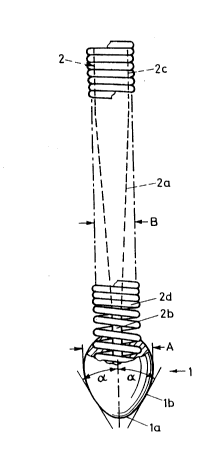
The gulde catheter shown ln Flg. 1 ls provlded wlth
a shaft 2 formed by a partly Teflon -coated wlre 2c made of
stalnless steel. At lts dlstal end wlre 2c ls conlcally
tapered ln one reglon 2a. At the front end of reglon 2a steel
wlre 2c ls hammered flat ln a reglon 2b for a length of
approx. 2 cm. As a result of the
trade-mark
2a
64680-549
~'
20179~1
..
above flat-hammering of steel wire 2 at the distal end,
the torsional reliability upon rotation of the catheter
is considerably enhanced. Also the danger of fatigue
is decreased. The danger of a torsion break of wire 2c
at its distal end is thus considerably reduced by the
flat-hammering. Experiments have shown, moreover, that
this can more or less double the tensile strength of
wire 2c. At least in the region 2b shaft 2 is not
coated with Teflon.
An olive-shaped tip 1 is firmly secured pull-out-
proof to the front end of shaft 2. Tip 1 consists
preferably of a silver alloy which is highly visible
roentgenographically. The maximum diameter A of tip
1 is preferably approx. 1 mm. The frontal rounded-off
end la of tip 1 leads to a flank lb, in which tip 1
exhibits comparatively little convexity. The angle of
this rotationally shaped flank lb to the longitudinal
axis of the catheter is approx. about 30 (angle ~).
The probe is provided with a partly Teflon-coated
spring 2d, which preferably consists of a
roentgenographically visible material, e.g., tungsten,
platinum or gold. Such springs are in themselves
known. In order that the probe have good flexibility
at its distal end, spring 2d behind tip 1 is uncoated
for a length of approx. 3 cm.
The catheter arrangement illustrated in Fig. 2
encompasses a probe in accordance with Fig. 1 as well
as a balloon catheter 3 with a distal aperture 24a
through which the probe is inserted from the front.
The probe can be shifted as well as rotated axially at
its proximal end by hand. Tip 1 follows these
movements. Figs. 3a to 3f each show a vessel 10 with
a lateral branch lOa and an occlusion 11. In
2~
accordance with Figs. 3a and 3b, tip 1 of a probe bent
forward at its distal end is advanced to occlusion ll.
In accordance with Fig. 3c, balloon 3 of the balloon
catheter is now also advanced until the balloon lies
directly in front of tip 1 in front of occlusion 11.
Because of the balloon catheter, the probe is now
additionally stiffened at its distal end, so that tip
1 can now be pushed through occlusion 11 with
particular thrust in accordance with Fig. 3d. The
closer balloon 3 is to tip 1, the greater the thrust
that can be imparted by axial displacement of the
probe. Stiffening of the distal end of the tip can
thus be easily varied. The suitably placed balloon
catheter thus supports the movement of tip 1. In the
now at least party recanalized occlusion, the balloon
can be introduced into this narrowing in accordance
with Fig. 3e. By briefly filling the balloon catheter
with liquid under pressure, the occlusion is now made
permeable again. As mentioned, this balloon can be of
the size suitable to accomplish this. Thanks to tip 1
the movements of the distal end of the probe can be
followed roentgenographically by the attending
physician particularly well and clearly.
The process pursuant to the invention for the
production of a probe will not be elucidated on the
basis of Figs. 4a and 4b. Wire 2c is shoved through
spring 2d until its front end projects forward from
spring 2d, as shown in Fig. 4a. The frontmost windings
21 of spring 2d are axially lengthened. A silver
solder piece 20 is now inserted between spring 2d and
wire 2c. The silver solder piece 20 is then heated by
a heating current until it melts. As soon as the
silver solder piece 20 has fluxed between windings 21
and assumed somewhat the form shown in Fig. 4b, the
heating current is removed, whereupon the solder or tip
20a immediately solidifies. Tip 20a is then ground
until it takes the suitable olive-shaped form. The
front end of wire 2c as well as the front end of spring
2d are thus firmly joined to tip 1.
The front end of wire 2c is preferably hammered flat
over a length of preferably approx. 2 cm before tip 1
is applied, so that here wire 2c has approximately the
cross section shown in Fig. 5. Dimension D here is
preferably approx. 0.12 mm and dimension C preferably
approx. 0.03 mm. The diameter of the not yet flat-
hammered wire 2c in this region is approx. 0.07 mm.
With the exception of the conically tapered region, the
diameter of wire 2c remains constant at approx. 0.5 mm.
This is also somewhat the diameter of spring 2d.
The distal end of the probe can be straight or bent
forward. In the latter case, the probe is
controllable, i.e., the direction of tip 1 can be
changed by one rotation of the probe around its
longitudinal axis. In Fig. 3a, such a rotation
prevents the probe or tip 1 to enter lateral branch
lOa. After tip 1 has formed, the proximal end of
spring 2d is soldered with wire 2c. The length of
spring 2d is approx. 20-25 cm and the conically tapered
region 2a of wire 2c is correspondingly long. Spring
2d is thus joined at one end with wire 2c and at the
other with tip 1.
The modified catheter arrangement according to Figs.
6 and 7 encompasses a balloon catheter 3 as described
above, a well known Y-connector 25 and a drive 26, with
which the shaft 2 with the tip 1 can be moved forth and
back in the directions of the double arrow 27, in order
to better penetrate an occlusion.
~17~
..
The drive 26 has a housing 26a, to which a grip 26b
is connected. Inside the housing 26a are two
antiparallel magnet coils 26d and 26e. The magnetic
field of one of the coils drives an iron core 26f, to
which the shaft 2 is fixed with a clamping nut 26g,
forth and the field of the other coil drives it back.
The shaft 2 can therefore be vibrated in its
longitudinal direction with the help of an accumulator
and a simple circuit, not shown in the drawings. The
frequency of the vibration is in the range of 20-200
Hz. The amplitude at the core 26f is in the range of
2 mm. Due to the damping of the shaft, the amplitude
A at the tip 1 is less and in the range of 1 mm. These
are the prefered ranges and special cases may need
frequences and amplitudes outside these ranges.
To have a exact vibration of the shaft 2, the mass
of the coils 26d, 26e and the housing should be much
higher than the mass of the core.