Note: Descriptions are shown in the official language in which they were submitted.
Z018~)~6
a4213221-US
INSIDE/OUT PERSPECTIVE FORMAT
FOR SITUATION AWARENESS DISPLAYS
Field of the Invention
The present invention pertains to air traffic
displays and particularly to display formats for an
air traffic alert and collision avoidance system
(TCAS). More particularly, the invention pertains to
TCAS display formats having three-dimensional
perspective color graphics.
Back~round of the Invent~n
The function of the TCAS display is to
present air traffic information, declare threats, and
provide advisories on potential air traffic conflicts
before the closest point of approach. The TCAS
display of the related art uses two-dimensional
graphics to convey traffic information in the own
aircraft's own protected volume of airspace. However,
since two-dimensional graphics can only depict
information on two (X- and Y-axes) of the three
dimensions required to completely represent spatial
traffic relationships for TCAS (X-, Y-, and Z-axes),
20~ )G6
-- 2
numerics are used to portray relative altitude on the
Z-axis. This two-dimensional plan view display of the
TCAS traffic information (supplemented with numeric
data tags for the third dimension, altitude) does not
provide a direct visual display of the dynamic spatial
relationships existing between air traffic in the
natural three-dimensional airspace. Interpretation of
such a display requires considerable time and mental
effort, in that it requires pilots to mentally
construct a three-dimensional image of the traffic
situation by combining graphically displayed azimuth
and range information with numerically presented
altitude information.
The related art TCAS display, therefore, is
limited to function as an aid to direct visual
acquisition of target aircraft, rather than as a
correct, veridical, and easily interpretable complete
"picture" of the current traffic situation. Pilots
simply use the presented information as a cue for
visual search to locate potential threats by direct
visualization of aircraft outside the cockpit.
Furthermore, since the traffic information is dynamic
and continuously updated, direct visualization will
require pilots to continuously alternate their
attention from reading the numerics on the head-down
TCAS display to the head-up search up for aircraft
Z01~ 6
- 3 -
outside the cockpit. Thus, using the related art TCAS
display, pilots often find it time-consuming and
confusing to visually acquire and process dynamic
changes in the air traffic situation under moderate or
high cockpit workload situations.
Attempts of the related art to solve the
problems of indirect visualization of conventional
displays have focussed on basic symbology refinement
for the two-dimensional TCAS display format. Efforts
have been made to reduce confusion and
misinterpretation by modifying the symbols. For
example, all the numeric codes were initially
displayed above the aircraft symbol with a "+" or "-"
sign to indicate relative elevation. The most current
baseline TCAS display presents the numerics either
above or below the symbol for conceptual
compatibility. No effort has been made to explore
other innovative approaches or to empirically validate
current design concepts. However, research on display
formats for other applications reveals potential
benefits of an innovative three-dimensional
perspective format. Ground-based perspective traffic
display formats have been studied in the related art
to demonstrate the advantages of utilizing perspective
graphics for portraying complex spatial situations.
Additionally, perspective displays for naval
2~)~8006
- 4 -
battlefield management systems have been previously
studied to examine the feasibility and advantages of
three-dimensional graphic presentations. Such studies
have shown significant advantages of three-dimensional
formats over two-dimensional formats.
Summary of the Invention
The present invention relates to formats for
the display of data in an airborne environment to
assist the pilot in being more cognizant of the
conditions in his or her airspace, thereby enhancing
his or her situational awareness. This format is
specifically desiqned for the Traffic-Alert and
Collision Avoidance System (TCAS), in which air
traffic information in a protected three-dimensional
volume of airspace surrounding an aircraft is
presented with respect to that aircraft. The present
invention implements three-dimensional perspective
graphics in color to display easily and directly
interpretable dynamic spatial relationships for the
TCAS system. This format is equally applicable to
military situation awareness formats where the pilot
needs to quickly and accurately recognize what traffic
and targets are in the surrounding airspace.
The invention uses three-dimensional
perspective graphics rather than a two-dimensional
' ,~
Z~ 31)06
-- 5 --
format supplemented with numeric data tags. The
advantaqes of the present invention are: the realistic
and intuitive portrayal of traffic information in
three-dimensional perspective that results in the
correct perception of the three-dimensional airspace;
appropriate use of color, shape and size coding that
is compatible with
the pilots' expectations; and the integration of
displayed situational information to facilitate rapid
interpretation by pilots. The primary objectives of
this new display format are: to enhance the speed and
accuracy of pilot's understanding of the egocentric
traffic situation; to minimize complex cognitive
processing and pilot mental workload; and to allow
pilots to preview and plan evasive maneuvers earlier
and more effectively in order to avoid potential air
traffic conflicts. Therefore, the function of the
TCAS display is greatly extended and ~s no longer
limited to cueing for visual acquisition of traffic
outside the aircraft.
3rief Descri~tion of the Drawinqs
Figure 1 shows the previously developed
two-dimensional TCAS display format of the related
art.
Z0~8~)~6
-- 6 --
Figure 2 shows a preferred embodiment of the
present invention which is a three-dimensional
perspective inside/out format for TCAS.
Figure 3 reveals another version of the
present embodiment of the invention.
Description of the Preerred Embodiment
The proposed invention solves (or greatly
minimizes) the problem of TCAS information portrayal
by employing a three-dimensional perspective display
format that emulates the spatial configuration of air
traffic in a natural, egocentric three-dimensional
airspace. The format presents a realistic view of the
outside world from the pilot's point of view with
appropriate depth cues to achieve the desired
three-dimensional perspective. This perspective is
referred to as an "inside/out" or "out-the-window"
view. The inside/out view format has the advantage of
direct mapping the three-dimensional air traffic
information to the display in such a way that all of
the necessary perceptual cues are integrated into a
single pictorial format. The display is divided into
two halves, one representing the forward view and the
other the rear view. This is analogous to driving an
automobile by naturally viewing forward through the
windshield while monitoring the traffic behind using a
2018~¢6
-- 7
rear-view mirror. The format enables pilots to
quickly interpret the overall traffic situation
surrounding their own aircraft without going through
complex cognitive processing.
Any number of methods may be employed to map
three-dimensional air traffic positions to a
two-dimensional plan view. The use of two-dimensional
graphics, supplemented with an abstract code for the
third dimension (e.g., numerical data tags for
altitude coding), is one method. This method of
information portrayal serves as foundation for
existing TCAS displays. Figure 1 illustrates the TCAS
display format 10 developed in the related art which
has served as the basic information display for
existing TCAS systems. As can be seen from figure 1,
graphical features are used to convey information
about other aircraft in azimuth, range, direction of
altitude change, and time before the closest point of
approach. A ring of 12 asterisks 12 is positioned at
a range of two nautical miles to provide information
on azimuth and range in reference to own aircraft 14
position. Upward and downward arrows 16 are employed
to depict the absolute direction of altitude change of
displayed air traffic. Redundant color and shape
coding are implemented to indicate the status of other
aircraft in terms of time before the closest point of
approach.
Z~8~)C 6
-- 8
The most noticeable deficiency in the related
art display format 10 is the use of numeric codes 18
to convey relative altitude. In order to determine
the relative three-dimensional positions of displayed
air traffic, a pilot cannot use simple pictorial cues
but must take the time to read the n~merical altitude
data tags 18 associated with each traffic symbol and
mentally integrate these data with the graphically
presented azimuth and range information. This reading
time can delay the pilot's decision about the position
of an aircraft that poses an immediate threat. Such
delays can become critical under high pilot workload
situations such as flying in turbulence. The use of
numerics 18 becomes increasingly cumbersome for
interpreting the egocentric air traffic situation as
the number of aircraft within the protected airspace
increases.
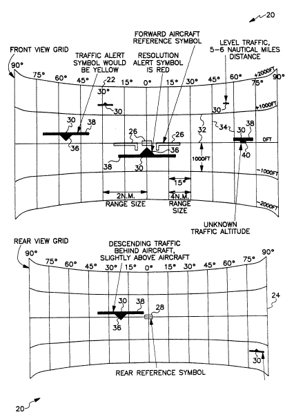
Pigure 2 depicts embodiment 20 of the present
invention which is an inside/out three-dimensional
perspective TCAS format. The resolution advisory is
integrated with the traffic display on which
information is portrayed in a three-dimensional
perspective format. The display presents an
"out-the-window" forward view 22 and a "rear view
mirror" image 24 of the air space behind the pilot.
The traffic is mapped onto a pair of cylindrical grids
znl8~G6
- 9 -
22 and 24 where grid 22 is used for the forward view
and smaller grid 24 maps the traffic behind the
aircraft. The forward view 22 includes aircraft
reference symbol 26 to indicate the pilot's own
heading and altitude. The rear view 24 includes a
simplified aircraft reference symbol 28 representing
direction and altitude directly behind the pilot's own
aircraft. The position of traffic symbol 30 relative
to reference aircraft symbol 26 or 28 is used to
represent the azimuth and elevation data. The size of
traffic symbol 30 indicates the range of the target.
The grid spacing is used for reference in determining
all three parameters. Each horizontal grid line 32
represents a constant altitude differential (for
instance, the ~iddle line is O feet and the first line
above middle could be +lOOO feet). Vertical grid
lines 34 indicate azimuth difference relative to the
pilot's own heading (center line = O de.grees, first
line to right is +15 degrees relative to your own
aircraft heading). The altitude and azimuth reading
are taken from the center position of traffic symbol
30. The range to the target is represented by the
size of the symbol. For example, a symbol which is
two grid 34 spacing in width would be 2 nautical miles
away, while a symbol only one grid 34 spacing wide
would be 4 nautical miles distant. The use of
Z~)~8t~ 6
-- 10 --
location and size gives the pilot not only excellent
absolute parametric values but also relative motion
cues. The shape of traffic symbol 30 is also used to
indicate vertical tendency. Symbol 30 with a triangle
36 above or below wing symbol 38 is ascending or
descending. Rectangle 40 above wings 38 indicates a
constant altitude, and rectangle 40 below wings 38 is
used to specify a traffic entity with unknown
altitude. Of course, other shapes can be used to
indicate such parameters as type of aircraft, aircraft
motion (in addition to altitude), and to indicate
priority of threat.
Color coding is also incorporated in the
symbol to indicate the status of the other aircraft.
Range, radar lock on (military), closing rate, or time
to impact can be conveyed with appropriate color
selection to indicate the level o~ threat. With this
perspective display, pilots can simply use the
integrated perceptual cues from a quick glance to
understand the dynamic traffic situation in the
three-dimensional airspace without the necessity of
direct visual contact. They can do advanced planning
without going through complex and difficult cognitive
processing. Consequently, pilots may rely on the
Z5 traffic display when direct visual contact is limited
in bad weather and flight by instrument is necessary.
Z~)180G`6
The mapping used in display 20 is not true
three-dimensional perspective view. The difference is
that all traffic is mapped onto cylindrical grids 22
and 24 at the appropriate elevation and azimuth
location and then scaled in size to reflect distance.
Note also that e~ch grid, 22 and 24, is not a true
perspective view in that vertical lines 34 are all
equally spaced. This is done so that targets to the
side are the same size as forward traffic symbols for
a given range. This simplified perspective view has a
big advantage in that much less processing capability
is required than for true three-dimensional
perspective view formats. This mapping technique is
an important component of the invention. The net
result is an easy to calculate display format which
provides the pilot with excellent situational
awareness.
The embodiment of the inside/out perspective
display format 20 described in this disclosure can be
implemented as a stand-alone display 40, having a
different cylindrical grid perspective as in figure 3,
or incorporated within other electronic avionics
displays such as a vertical speed indicator,
electronic attitude director indicator (EADI),
electronic horizontal situation indicator (EHSI), or
radar display. Variations in symbology such as color
2~)180G6
- 12 -
and shape coding can also be easily implemented. Such
variations may be used to indicate a particular
status, including whether the traffic is approaching
towards or receding from the pilot's craft, or
describe the identification characteristics of the
traffic entity being symbolized. As the aviation
industry extends the resolution advisory function of
TCAS to include both vertical and horizontal
maneuvers, a three-dimensional perspective format will
allow pilots to comprehend the dynamic traffic
situation quickly and to verify suggested maneuvers
easily.