Note: Descriptions are shown in the official language in which they were submitted.
-1 -
MEASUREM~NT 01~ ECr~RICAL RESISTIVITY
OF' PARTICULATE ENTRAINED IN A GAS STR~AM
BACICGROUND OF TIIE INVENTION
~ .
Thls inventiorl relates -to the measuremen-t o-E
the electrical resistivity of particulate m~terial
entrai1led in gas s-~reams, and, more partlcularly, to
the measurement of the elec~rical resistlvity of the
entrained particulate material in power plant
combus-tion gases that are to be subJected to
10 elec tros ta-tic precipl tation l;rea-tmen-t .
In a coal-rilecl power plant, coal ls burned
to heat air, w~1icll in turn bolls water to form
steam. The steam drives a turbine and thence an
electric generator, producing electriclty. Besides
15 heat, the burning Or the coal produces gaseous
pollutants such as sulfur and nitroeen oxides, and a
solid par-ticulate l~nowr1 as fly ash. Environmental
protection laws mandate that -the amoun-ts oi` gaseous
pollutants and soli~ par-ticulate emit-ted ~rom the
20 power plant be malntained a-t acceptably low levels,
and tl1e present invention deals generally with the
technology for controlling particulate emissions.
One widely used approach ~or removlng the
particula-te fly ash from combus-~ion gas streams is
25 electrostatic precipitation. The combusltion gas
stream with entrained particulate is passed be-tween
hlghl~y charged electrodes that ionize the particles
so that they are attracted to, and deposited upon, a
collection electrode. The particula~e may
30 optionally be charged prlor to entry into the
precipltator to increase the eff:lciency of removal.
The cleaned combustion gases are released to the
atmosp}lere, and the precipitated particulate is
reînovecl ~`rom the collec~ion electrode.
33
--2--
The efriciel1cy o~ opera~ion Or electrostatlc
preclpitn-tors depe11tls m~r1~edly upon the electrical
reslstivity of tlle par~iculate. If the resistivlty
is -too high a collection current cannot be induced
to rlow between the elec-trodes of the precipitator
so -that the ~blll-ty t:o collect pnrtlc~l~te i8
reduced sometimes severely so. There exist
conditionin~ procedures and apparatus for altering
the conductivity of t~1e par-ticula-te by in~ection vf
conditioning agents into the comb~stlon gas stream
prior to l-ts entering the electros-ta-tic
preclpitator.
An exalllple of such a treatme~t procedure is
that cllsclosed in US pa-tent ~ 993 429 and thls
approach has become widely accepted and used
-throughout the Unitecl S-tates and the world. In thls
approach a conditioning gas such as sulfur trioxide
or ammonia is inJec-ted in-to the combustion gas
stream. In the case of sulfur trioxide the
conditioning gas reacts wi~l water in the gas stream
to produce sulfuric acid that ls Aeposited upon -the
surface o~ the particulate. The lonized sulfurie
acid reduces the elec-trical resistance of the
particulate which in turn ralses the elee-trical
conductivit<y of the rly ash partieulate so that the
elec-trosta-tic precipitation treatment works well.
Conditioning treatments are routinely used where -the
sulfur content of t~le coal burned in the power plant
is so low that the electrical reslstivity of the
resulting particula~e is too high to permit the
electrostatic precipitators ~o operate properly.
The proper amount of condltioni1lg gas to
inJect and the best operating settings of the
preclpltators Inust be cleterlnlned to permlt optlmum
3S opel~ation o~ the systelll. rO achleve operatlng
control o~ the precipltator and/or the eond:ltloning
systeln lt ls desi1a~le to 1cnow the eleetrlcal
)133
resis-tlvlty of t~1e p~rtic~ te ~eln~ precipl-tated on
an ongoing bas:Ls, using Ineasurements within the
apparatus. With tl1is kno~ledge, -the operation of
-the system cal1 be op~lmize~ ln real time under
manual or au-tomatic con~rol. If -the resistivity of
the particula~e is no~ 1~nown, then the proper
operatlng parameters can OI1ly be approxima-ted, based
upon the experience o~ t11e operator.
There have been developed var1Ous types of
apparatus for 1neasuring the elec-trlcal reslstivity
of the particulate. '1'hese include the Southern
Research Institute poin~-to-plane probe, the Wahleo
cyclonic probe, and ~lle lnterlocking comb probe.
All of these probes pel~lnit meaSureme11t of some
resistivity parameter, but all also suffer from .
certain s}1ortcomings, The obJectlve of the
measurement is to detertnlne the resistlvl-ty o~ -the
par-tic~late w1der as realistlc condl-tions as
possible, simulating the conditions wit}1in the
electrostatic precipitator. None oi the 1~nown -types
of probes collect truly representatlve samples of
the particulate un~ler the conditiorls of
precipitation. Moreover, none of th~ known
apparatus are continuous or semicon-tlnuous in
25 opera-tion, and must be lnser-ted into the flowlrlg gas .
strealn on an intermitten-t basis to accompllsh the
measuremen-t.
There therefore exlsts a need for an lmproved
apparatus and rnethod ~or collecting samples and
measuring the resistivi~y of particulate entralned
in a gas stream, in a wide variety o~
clrcums-tal1ces. T111s need ls particularly aoute for
the Ineasuremerlt Or ~he resistlvity of fly ash
par-tlculate ln ~he combustion gas stream of
coal-f'lred power plantæ. Such an approach desirably
would collect a represenl;a~lve sample of par-ticwlate
under prec:Lpitator opera~ g conditions. Also, the
approach ~hould permlt continuous or nearly
COIItillUOUS measurelne7lt of reslstivity, -to allow
rea~ ne, contlnuous con~rol of tlle gas cleanup
system, where present. The present inven-tlon
fulfills t11is need, an~ further provides related
advantages.
SUMMARY OF T~IE INVENTION
The present inve~tlon provides an apparatus
(also termed a measurelllent probe or probe) and
method for conduc-tillg measurements of the elec-tric~l
resist:lvity of samples Or particulate obtalned from
flowing gas s-treams ln wlllch the partlcula-te l~
entrained. The apparatus o'btalns samples of the
par-ticulate tha-t are highly representRtlve of the
actual particula-te mass on -the collection pla-tes o~
-the electros-tatic precipitator, beoause -the samples
are gathered un~er conditions approximatlng tllose of
the precipitator operation. The apparatus is
automatic and semi-continuous.
In accordance with the inven-tion, partlculate
resistivity measurement apparatus comprises a hollow
cylindrical, substrate made , o~ an elec-trical
insulator; two i~lterdigl-tated electrodes spirally
; wound Oll -the substra-te, including a measuremen-t
elec-trode, ancl a referellce electrode a measurement
power supply that applles a measuremen-t voltage
between the measurement electrode and the reference
electrode; and a curren~ rneasurement meter that
measures the current flo~ing between -the mea~urement
: 30 electrode and the refererlce electrode due to the
applied Ineasurelnent volta~fe.
More speclEically, partlculate resistivlty
measurelllent apparatus comprlses a substrnte; two
adJacently positloned electrodes supported Oll the
,
:, .
2tDl~;~(} ~;3s.3
su~stra-te, lnc1uc~ a measurement electrode having
a composi-te structure lncludlng a measurement
COII~Uctor, a pa:lr Or confine]nent conductors, one on
eltller side of tlle measurement conductor, and an
insulation layer betl~een each o~ the confinement
conduc-tors and ~he measurelnent conductor, and a
reference electrode; a measurement pow~r supply that
applies a measurement voltage be-tween the reference
elec-trode and tlle Ineasurement conductor o~ the
10 measurement electrode; and a current measurement
meter that measures the current flowing between the
reference electrode and the measurement electrode
due to -the appl1ed measuremer1t volta~e.
In a par-ticularly preferred approach,
15 particulate resistivlty measurement apparatus,
comprises a cylin~rlcal subs-trate -that is sealed at
the ends -to permit control of the interior pressure
of the substrate, and is made o~ a porous ceramic; a
pressure controller comlllunica-~ing wl-th the interior
20 o~ l;he subs~rate, the pressure controller includlng
a vacuum source of a pressure below atmospheric, a
purging source of a pressure above a-tmospheric, and
a valve that is controllable to connect the interior
of the substrate to either the vacuum source or the
25 purging source; a perforated shield around the
ex-terior of the substrate; two interdigitated
electrodes spirally wouncl on the substrate,
including a measuremen-t electrode havlng a composite
structure including a measurement conductor, a pair
30 of confinelnent conductors, one at a greater
cylindrical radius and one at a lesser cyllndrical
radlus than the measuretnent conductor, and an
insulation layer between each of the confinement
concluctors and tl1e measurelllent conductor, each of
the con~lnement COII(Iuc~Ot`s belng at ground
potential, arld a refe1erlce electrode a measurement
power supply tllat applle,s a measuremel1t voltage
~ .
be-twcell t~le re~elellce elec~.ro~e and the measurement
conductor of the measurelTIent elec-trode; and a
currell-t measuremen~ meter -tha-t tneasures th0 current
flowlIIg be-tween the reference electrode ancl the
5 measure~en-t conduc~or ~ue to the applled measurement
vol-tage.
In the preferred approach, -the measurement
electrode and the reference electrode are spirally
wound in an interdigltated fashion on the
10 substrate. The confillelllent conductors and -the
measurement concluc-tors are grounded, and the
c~nflnement conductors minimlze e~traneous
influences on the resistlvity measuremen-t. A
vol-tage ls applied ~etween -the reference electrode
15 and the measurement conductor. The current that
flows as a resul-t of the applied voltage provides a
measure of -the resistlvlty of the par-ticulate in the
gap between the measuremellt elec-trode and the
reference electrode.
Thls appara-tus is operated in a
semi-continuous manner. A sample ls collected b~
drawlng a partial vacuum on the porous ceramic
cylinder or cup to clraw a sample of part:Lculate i.nto
-tlle gap between the measurement electrode and the
25 reference electrode. In an important variatlon of
this collection approacll tha-t can be employed as
appropriate, a conduc-ting shield is positloned
around the cylindrical substrate, and a collection
voltage applied between the shleld and the
30 substrate. The particulate is ioniæed as it enters
the npparatus. The ionized particulate is then both
drawn toward the substrate by the gas flow and also
propelled to~ard tlle substrate by electrostatic
force. Wherl a surficiellt sample is taken, the gas
35 ~low through tlle ceralllic slows to a oalibrated level
and the collec~lon voL-tage, lf any, is
discollt:Lnued. A measurement of resistlvit~ is take
lBt~83
. ,,
by applying tlle exterllal measurement voltage be-t~een
the reference electrode and the measurement
con~uctor portton Or tl-~e measUremerlt electrode.
Because they are otherw~se in~ula-ted from
5 each other, a current can flow between the reference
electrode and ~he measuremellt electrode Dnly through
the particulate. From a measurement of the eurrent
flowing through -the particulate, -the resistlvity is
calculated, or, eqnivalell-tly, a calibration of the
10 measured current to -the optlmal operating parameters
of -the electrostatlc precipitator ancl/or
conditloning system is made. When the measurement
ls complete, the pressule Oll -the interlor of`-the
pOl'OUS CerallliC Cyl:Lllder is reversed, and the
15 collected partlculate sample is blown away by the
flow o~ gas out -~hrough the pores of the ceramlc.
The apparatus is ready ~o repea-t the measuremen-t by
tal~in~ a new sample of -the partlculate.
The invention also encompasses -the process
20 for accomplishing -the measurement usin~ the
apparatus, as described. Generally, a process for
: performing a resis-tivity measurement o~ a
partlculate entrained in a moving gas stream o~
combustlon gas -to be subJec-te~ to an eleetrostatie
25 precipitation process, comprlses the steps o~
collecting a sample Or t}le particulate such that the
partlcles enter the samp]e under subs-tantially the
same kinetic movemellt condltions as found in the
moving gas stream; and measuring the electrical
resistance of -the sample.
This apparatus ancl process are an advance in
the operatlon o~ power plant gas eleanup procedures,
providin~ an automated, seml-continuous measure~ent
of electrical res:lstivlty o~ partlculate in the
combust:Lon gas strea1n. The measurement is
reproduelble, ~ecause the placement of the apparatus
ls constant ancl the condiL;ions of sample collectlon
~18(~33
~.~
nre uniform rroln test -to test. ~ e apparatus has no
movillg parts ~i-t~lin -tlle gas stream, and is reliable
to operate. It is no more costly than other types
of resis-tivlty measulement devlce~, and less
expensive than some. ~ther features of -the
inventlon wlll be apparen-~ from the following more
de-talled descrip-tlon Or the preferred embodiment,
talcen ln conJunction wlt~l -the accompanying drawings,
whic~l illustrate, by ~ay of example, the prlnciples
of tlle lnvention.
BRI~-~ DESCRIPTION 0~ THE DRAWINGS
; Figure 1 is a schel1latic drawing of a power
plant combus-tion gas cleanup apparatus
Fi.gure 2 ls a schelllatlc side sectlonal vie~
of one embodlment of an apparatus for ~easurlng
reslstivity, wi-th associa-ted equlpment and
instrwnentation shown plctorially.;
Figure ~ is an enlargement of ~ detall o~
Flgure 2, lllustrating -the structure and
interrelatlonshlp of -tbe electrodes;
Flgure 4 is a perspective vlew of one
cons-tructlon ~or tlle porous cyllnder used to collect
the partlculate;
Flgure 5 is a sec-tional vlew of the cyllnder
25.of Figure 4 transverse to -the cylindrlcal a~is,
tal{en generally along lines 5-5;
Figure 6 ls a sec-tlonal vlew of the cyllnder
of Flgure 4 transverse to the radi~s of the
cylin~ler, talcen generally along lines 6-6; ancl
Figure 7 is a schelllatlc slde ~ectional vlew
of` a seconcl embodlmQIlt of an apparatus for measuring
resis tiv~ y.
~P3~ 13
9_
l)E'I'~IL~D DESCRII~rION 0~ IIE ~R~F~RED ~MBODIMENT
The present inverl~lon is preferably used in
con~unc-tion ~lth an apparatus 10 for precipitating
par-ticula-te rro~n a combus~ion gas stream, ~rhich is
depicted in Figure 1. In a conven-tional coal-~ired
power plant, coal ls burned by a combustor 12, and
the resulting hot combus~ion gas i9 passed through a
boiler 14, w~lere it lle~ats and boils water. The
resul-tlng steam in a loop 1~ flows -to a
turbirle/gerlerator se-t 18, where electricity for
consumption is produce~. The steam is condensed,
and the water flows bacl~ -~hrough the loop 16.
Tlle combustlorl gas stl~eam leavlng the boller
14, indicated ~y nuIneral 20, cannot normally be
exhaus-ted direc-tly -to -the atmosphere, because it
contains the particula-~e or fly as~ resulting f`rom
the combustion 12. If lt were exhausted to the
atmosphere, the fly ash would deposlt on everythirlg
surrounding the power plant, leavlng a thlcIt coating
of soot. Fortuna-tely, t~le fly ash can be removed
from tlle combustion gas s-~ream 20 by electrostatic
preclpitator technology, lf the fly ash has a
suf~iciently lo~r electrical reslstlvity.
The fly ash produced by some types of coal,
particularly coal containirlg a low sulfur con-tent,
has too high an electrical reslstance to be
processed ln an electrostatlc precipltator, and
-therefore must be condltloned before enterlng the
preclpitator. It ls known -to inJect a conditionlng
gas into the combustion gas s-tream by a conditloning
apparatus 30, lllustratetl schematically ln Figure 1.
'l'he conditloI~ lg apparatus 30 inJects a
con~lltlorlirlg agent (l;hat Inay be a gas, a ll(luid, or
a sollcl, but is pref`erably a gas) lnto the
combustlon gas stream 20. The conditloning agent ls
preferably sul~ur trloxicle, but may be, for example,
L8~ 3
--:L U--
otller gaseous oxlcles Or sulfur, am~onia, or water
vapor. 'rhe preferred apparatus 30 therefore
includes a source 32 Or the con~l~ionine gas, and a
plurality of inJec-tor nozzles 34 that e~tend into
the colnbustion gas stream 20 to inJeet the
condlt:Loning gas dlrec-tly into -the stream 20. A
valve 3~, or other flow control deviee, meters the
conditioning gas into tlle combustion gas s-tream 20
through the nozzles 34~ A preferred souree 32 is
disclosed ln US paterlt 3,993,429, and a preferred
eonstruetioll o~ the no7,zles 34 is diselosed in US
paten-t 4,179,0~1. 'I~he disclosures of both of these
patents are lncorporated hereln by referenee.
The ln~ec-te~ conclltiolllng gas moleeules reae-t
15 with -the partieulate in -the gas stream to lnerease
the eonduetivity of' -the partieulate, or,
alternatively sta-t~d, -to lower its resistivi-ty. In
the ease of the preferred sulfur trioxide
eoncll-tioning gas, the conditioning gas reaets wlth
the residual molsture in -the combustion gas to form
sulfuric aeid on the surface of the partleulate,
which increases -the elec-trical eonduetivity of the
particulate.
After conditioning, if any, o~ the eombustion
gas stream 20, the combus-tion gas flows to an
electrostatic precipitator 40. The preeipi-tator 40
may be of any of the many types eommereially
available and l~nown in the art. The preeipitator 40
ineludes a plurality of electrodes 4Z eharged with a
hlgh voltage, and groundecl preeipitation plates 44.
The partieulate in -the gas stream 20 is ionized by
the eleetrostatie field established between the
eleetrocles 42 and tlle plates 44, and is attraeted to
be cleposlted as a layer ~ upon the plates 4~ for
subsequerlt removal. The operation of the
eleetrostatle preelpl~ator 40, inelucling the vol-tage
and eurrellt appllecl to tlle eleetrodes 42, the
33
L
rapplng of the plates ~ to cause the collected
particulate -~o fall in~o lloppers, ancl auxiliary
control ancl (llsplay runc-~lorls are under the control
of nn electros-tatic preclpita~or controller 48.
To operate tlle source 32, the valve ~6, and
the controller 4~ ln an op-tlmal manner, lt ls
necessary to assess the electrical resistivity oE
the particulate being deposi-ted as the layer 46 in
the electrostatic precipi-tatoI 40. The present
inventioll provides measurement apparatus for :th~t
pUl'pO S e.
A partlculate resistivity measurement
apparatus 60 is moun-ted within or upstream of
(closer to tlle combustor 12) the electrostatic
precipitator 40. The apparatus 60 provides a
semi-continuous measurement of the resistlvlty of
the particulate cleposlted uncler conditions similar
to those experienced by the layer 46 in the
precipitator.
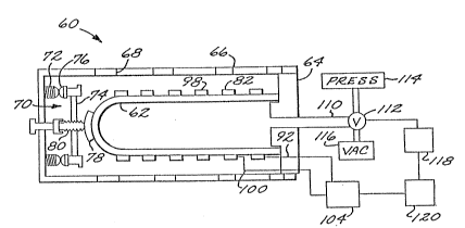
Referring to Figures 2 and 3, the apparatus
60 includes a porous cylinder 62 that is closed at
one end. This cyllnder 62 is also variou~ly
re~errecl to as a cup or ~himble. The cylinder 62 is
preferably `a ceramic such as aluminum o~ide, but may
be a glass, a high ~empera-ture plastic, or other
suitable materlal. The cylinder 62 should have a
. reasonably low coefflciellt of thermal expanslon and
must be structurally sound but porous ~o the passage
of pressurized gas. Such cylinders are r.eadily
available as 35~47 percent dense alumlnum oxide
closed-one-encl cyl:lnders from Norton Co. The
cylincler 62 ls mounted to a fi-ttlng 64.
Also mounted to the fitting 64 is a shielcl 66
that has a plurallty of perforations 68 or holes
therethrough to admit ~he partlculate-laden gas,
bearing lts entra:Lnecl partlculate, to -the lnterlor
o~' the shield 66 ancl -to the outer surface of the
33
-12-
cyllnder ~Z. (~n unperrorated shield with ~n entry
port, such as wlll ~e dlscussed ln relation to the
em~odimellt of Figure 7, can also be used.) The
distal end of the sllleld 6b is closed, and supports
a pressure clamp 70 tllat llolds the cylinder 62 in
place agalnst the fitt1rlg 64. The press~re clamp
includes a palr of posts 72 that support a cross
piece 74. 'I'he cross plece 74 is preferably
flex~.ble, and ls mourl~ed to the posts 72 using
expansion washers 76 that permi-t the shield 66 to
expand with increasillg tempera-ture whlle still
retainlng pressure agains-~ the closed end of the
cylinder 62 througll a pressure pad 78. The pressure
pad 78 ls mounted to -the cross plece 74 with a
: 15 compression screw 80 that may be tightened or
loosened to ad~ust the retalning pressure agalnst
the end of -the cyl:klder 6Z. Thls arrangement
provldes a rellable, ad~ustable approach for
mountlng -the elements Or -the appara-tus 60 together.
Wrapped aroun~ the ou-ter circum~erence o~ the
cyllnder 62 ln ail lnterdlgitated, spirally wound
conflgura-tion are two elec-trodes, whose structure
and rela-tionsllip are deplc~ed in more detall in
Flgure 3. A measurement electrode 82 has a
composite .structure with a single measurement
conductor 84 sancatrichecl between two conflnement
conductors 86. An lnsulation layer 88 separates the
measurement conductor 84 from each of the
confinement conductors 86 on elther side. The two
conflnement conductors 86 are grounded.
~ reference electrode 98 ls a solid
electrical conductor that is spirally wound ~round
the cyllnder 62 in an interdigitated fashlorl wlth
the measurelnellt electrode 8Z.
The referellce electrode 98 ls connected
throuell a lead 100 to tlle ~llgh side of a measurement
power supply 94. The low s:lcle of the power supply
.
3t.~1~3
-l3-
94 is grounded, ~u~ connected ~o ~he measurement
concIuctor 84 of ~Ile measuremeIl~ electrocle 8~ through
a lead 92. TIle po~er su~)ply 94 applies a voltage,
for example 1000 volts, between the reference
electrode 98 and t~le measurement conductor 84. If
the gap be~ween ~he rererence elec-trode 98 and the
measurement conduc-tor 84 i~ flllecl wi-th an
electrically conducting materlal~ depicted as a
conducting particulate mass 102, a eurrent flows.
The current rlo~ing under this impressed voltage is
measured by an ammeter 96 in ~he circuit. Thls
current ls a direct measure of the resistlvlty of
the partlculate material in the gap.
The power supply 94 and the amme-ter 96 are
typicallY packaged toge-ther as an electrlcal
controller 104.
The preceding dlscussion has dealt wi-th the
manIler of making tlIe elec-trlcal resistivity
measurement, after a particulate mass 102 has been
collected between the electrodes 82 and 98. The
following dlscussion deals wLth the collection of
the sample of partlculate and its dlsposal after the
resistivity measurement has been comple-ted.
A gas line 110 communlcates wlth the interior
of the cylinder 62 through an openlng In the fltting
64. The gas line 110 connects externally to a
three-way valve 112. 'i'he valve 112 can be operated
to connect the interior o~ the cyllnder 62 to a
pressure source 114 or a vacuu~ source 116. The
valve is controlled by a gas controller 118.
The electrlcal controller 104 alld the eas
controller 118 are both uncler the eontrol o~ a
central controller 120. The eontroller 120
esta~llsIIes a sequerIce of operatlon of the
electrlcal voltages in the controller 10~ and the
pressure or evacuatlon instructlons ~n the
conI;rollt-~r 118. It also monltors the current
t3~3
-- I 'I ^-
measurecl by tlle amme~er 96, which is an indica-tlon
of tlle resistlvlty alld thence the nature of the
partlcula-te belllg measurec~. Thls latter information
is used by a hulna2l opera-tor or a compu-ter that has
been programmed wi~ll an algorithm which relates
operation of the pl~eclplta-tor and conditio~ g
appnratus to particulate conductivlty. When
operated in an automa-tic mode, the controller 120
can send command sigllals to the electrostatic
precipitation controller ~8, the valve 36, and the
source 32.
A partLcularly preferred construction of -the
cylinder 62 ls illus-trated in Figures 4-6. The
cylinder 62 could be forlned with a smooth outer
wall, but su~h construction mlg~-t permit -the
electrodes 82 and 98 to shift in position with
repeated expansion ancl contractlon during
-temperature cycling. A cylinder 62~ has-a plurality
of longitudinal grooves 130 in its ou-ter perlphery
ex-tending parallel to -the axis of the cyllnder.
There are also two interdigltated spirally wrapped
grooves 132 and 134 in the outer perlphery.
The reference electrode 98 is wound spirally
around the cyllnder 62 7 in one of the spiral
grooves, here the groove 132. The measurement
electrode 82 is wound spirally around the cylinder
62' in -the other spiral groove, here the groove
13~. The placement of the electrodes in the grooves
preven-ts significan-t shirts of posl-tion that mlght
produce questionable resistivity results. The
particulate mass 102 is collected in the portlon,
here indicated by tl~e numeral 13~, of the
longitudinal grooves 130 that is between the
supportlng structurt-~. rlle particulate sample i~
reproduclble both lll amount and plncement between
the electrodes 82 ancl 9~, ensuring reproducible
results.
83
The apparat~s 60 rullctiOns in the followi~g
manner. Tlle gas con-troller 118 is operated to draw
n mil~ vac~lulll on ~lle ln~erlor of the cyllnder 62 by
connecting -the gas line 110 to the vaeuum souree 116
through the valve 112. Combustlon (or other) gas
wlth entrained particulate flows through` the
perforatlolls 68 of the shield 66 and the
particulate mass lOZ ls deposited upon the outer
surface of the cylinc~cl 6Z between and over the
lO elec-trodes 82 and 98. The gas flow through -the
vacuum source 116 is initlally rapld because there
is little resis-tance ot;ller than -the reslstance
offered by -the porous ceramic of the eylinder 62.
As -the particula-te layer grows ln thicl~ness the
15 flow clecreases because of the flow resis-tance
offered by the mass of par-tlc~late 102. When the
flow resistance increases ~o ~ calibrated amount
the controller lZ0 deter~llirles tha-t a suf~lcient mass
102 is present to conduc-t a measurement.
To this point of -the cycle the measurement
power supply 94 is not operating. When the mass 102
is of su~iclent thicl{ness the power supply 94 is
operated to apply the measurement voltage between
the reference conductor 98 and the measurement
25 conductor 84 of the measurement electrocle 82. The
only current path to complete the eireult is through
the accumula-ted particulate mass 102 and the
current measured by the amme-ter 96 is lnversely
related -to the resistance of the mass 102. In this
30 manner the electrlcal resistance of the partleula-te
ln the mass 102 ls determlned. This reslstarlce ean
then be related to electrical resistlvity or simply
comparecl to calibratiorl s~andards -to determlne the
operatiorl of the precipltator and/or the
35 condil;ioning gas supply.
A~ter tlle measurelllerlt is complete the gas
controller 118 is operated to connect the gas lLne
, ~,
110 to tlle pressure soul~ce 114 through the valve
112, pressurizing tlle interior oi the cylinder 62.
The accumulated mass 102 is blown away by the gas
escaping ~hroug~l tlle pores oi~ -the cylinder 62. The
apparatus 60 is -then reacly for another measurement.
Anothel embodimerl-t of the measuremen-t
apparatus 10' is illustrated in Figure 7. The
cylilltler 62, electrodes ~2 and 98, gas flow eystem,
and electrical resistance circuitry for this
10 embodiment are identical to -those dlscussed
prevlously. The difrerence resides in the mode of
collection of the par-ticula~e sample. There are -two
driving :~orces for the collection in the embodiment
of Figure 7. One is tlle gas inflow -throueh the
15 porous wall of the cylin(ler 62, a~ discussed
previously.
The other is an electrostatic drivlng force
that si]nulates tlle electrostatlc compaction ~orces
prod~ced between the electrode 42 and the pl~te 44
20 of the electrostatic preciplta-tor 40. Simulating
the electrostatic compaction force may be important,
because the resistivity of the partlc~late mass lOZ
may be dependen-t upon the extent of compaction.
To simulate the electrostatlc compactlon
25 force, the shield 66 is made of a conducting solid
such as a metal. Tlle shield 66 is charged
electrostatically witll respect -to the electrodes 82
and 98 during the sample collectlon periodt usin~ a
collection power supply 15U. If the par~iculate
30 particles are ionized, they are driven inwardly
toward the cylinder 62 with an electrostatlc driving
force, as indicated schematically by arrows 152.
The compaction voltage ~e-tween the shield 66, on the
one hand, and the elec-trodes 82 and 98, on the
35 othel, is ~ypically sufflcient to produce a voltage
o~ ~ to 5 I~:llovolts pel lnch of` separntion between
the shielcl 66 ancl the cylincler 62, but may be
33
-17-
ad~usted -to optimally sllnula-te the behavior Or the
p r e c l p i t a-t o r
The gas-cntralned particulate enters the
appara-tus ln ' -tlllough a port 154. As -the
particula-te enters ~he apparatus, it passe~ between
oppositely charged electrodes 158 and lbO, which
have a voltage typ.Lcally of about ~-5 kilovolts per
inch Or separa-tion be-tween them. The particles ln
the gas stream are ionized, so that they may be
electros-tatically accelerate~l from the shield 66 to
the cylinder 62, as well as being drawn toward the
cylinder ~2 by tlle flow1ilg gas stream under the
influence of the partial vacuum applied to the
interlor Or the cylinder.
Tlle present apparal;us and process thus
provide a probe for measuring the properties of
particulate that is deposited under conditlons
similar to -those ln the electrostatic precipitator.
Altllough a par-ticular embodiment of the inventlon
has been descrlbed in detall for purposes of
lllustration, various modiflcations may be made
without departlng from the spirlt and scope of -the
lnven-tlon. Accordingly, the inventlon is not to be
llmited excep-t as by the appended claims.