Language selection

Search

Patent 2018175 Summary

Third-party information liability

Some of the information on this Web page has been provided by external sources. The Government of Canada is not responsible for the accuracy, reliability or currency of the information supplied by external sources. Users wishing to rely upon this information should consult directly with the source of the information. Content provided by external sources is not subject to official languages, privacy and accessibility requirements.

Claims and Abstract availability

Any discrepancies in the text and image of the Claims and Abstract are due to differing posting times. Text of the Claims and Abstract are posted:

  • At the time the application is open to public inspection;
  • At the time of issue of the patent (grant).
(12) Patent: (11) CA 2018175
(54) English Title: PULPER
(54) French Title: DESINTEGRATEUR
Status: Deemed expired
Bibliographic Data
(52) Canadian Patent Classification (CPC):
  • 92/52
(51) International Patent Classification (IPC):
  • D21D 1/00 (2006.01)
  • D21B 1/34 (2006.01)
  • D21D 5/02 (2006.01)
(72) Inventors :
  • HAUTALA, JOUKO (Finland)
(73) Owners :
  • VALMET CORPORATION (Finland)
(71) Applicants :
  • HAUTALA, JOUKO (Finland)
(74) Agent: BORDEN LADNER GERVAIS LLP
(74) Associate agent:
(45) Issued: 2000-01-04
(22) Filed Date: 1990-06-04
(41) Open to Public Inspection: 1990-12-05
Examination requested: 1997-01-07
Availability of licence: N/A
(25) Language of filing: English

Patent Cooperation Treaty (PCT): No

(30) Application Priority Data:
Application No. Country/Territory Date
892,737 Finland 1989-06-05

Abstracts

English Abstract


The invention relates to a pulper for
breaking materials containing fibre pulp,
more particularly for breaking materials
containing paper pulp or corresponding. It
comprises a feed chamber (2) restricted by
the pulper housing (1), a rotor unit (3)
or corresponding in the feed chamber (2)
adapted to be moved by means of a drive
unit, a screenplate (6) with perforations
(5) in connection with the rotor unit (3)
or corresponding and a space (8)
restricted by a housing (7) or
corresponding and situating on the
opposite side of the perforated
screenplate (6) as seen from the rotor
unit (3) or corresponding for receiving
the broken material. The space (8)
consists of a screening unit (9) having a
first partial space (10) which is in
direct connection with the screenplate (6)
connected with the rotor unit (3) or
corresponding, and which has a discharge
connection unit (15) for the rejected
portion, a second partial space (11) for
the accepted portion, which partial space
(11) has a discharge connection unit (16)
~or the accepted portion, a partition wall
construction (12) or corresponding in the
middle of said first (10) and second (12)
partial space, consisting at least partly
of a perforated screenplate (13) and a
cleaning device (14) adapted to be moved
relative to the screenplate (13) by means
of a drive unit.


Claims

Note: Claims are shown in the official language in which they were submitted.


CLAIMS
1. An apparatus for pulping and screening materials
containing fiber pulp, said apparatus comprising: an upper
part defining a pulping section for breaking down said
materials and a lower part defining a screening section for
prescreening said broken materials;
said pulping section including:
a feeding chamber delimited by a housing, a rotor unit
positioned in said feeding chamber, a drive unit for rotation
of said rotor unit and a first perforated screenplate in a
bottom portion of said pulping section through which an
accepted portion of said broken material is fed into said
screening section;
said screening section including:
a space also delimited by a housing and positioned on the
opposite side of said first perforated screenplate, a
stationary partition wall for dividing said space into a
first partial space and a second partial space;
at least a portion of said partition wall including a
second perforated screenplate;
said first partial space being in communication with said
feeding chamber for receiving said accepted portion of said
material through said first screenplate;
said second partial space being in communication with
said first partial space through said second screenplate for
receiving material accepted by said second screenplate;
a first partial discharge outlet in communication with
said first space for discharging the portion of material
rejected by said second screenplate;
a second discharge outlet in communication with said
second partial space for discharge of the portion of said
material accepted by said second screenplate; and
a cleaning device provided in said first partial space
and rotatable with respect to said second screenplate of said
partition wall.
2. An apparatus according to claim 1, wherein said


housing defining said space is substantially cylindrical and
wherein said second screenplate is also arranged to form a
substantially cylindrical surface, the center line of which
is parallel with the center line of said housing, said
cylindrical surface formed by said second screenplate being
restricted at least partly by the bottom of said housing and
on the opposite end at least partly by a part of said
partition wall.
3. An apparatus according to claim 1, wherein a shaft of
said cleaning device, which is connected to a drive unit, is
adapted to pass through the second partial space and wherein
a supporting structure extending radially from said shaft is
connected to said shaft, said supporting structure
supporting, at its end part, elongated, blade-like members
constituting said cleaning device.
4. An apparatus according to claim 3, wherein said shaft
is sealed at a part of said partition wall between said first
and said second partial spaces.
5. An apparatus according to claim 3, wherein a
reduction gear is provided between said drive unit and said
rotor unit and said cleaning device.
6. An apparatus according to claim 3, wherein said shaft
is sealed at a part of the partition wall between said first
and said second partial spaces.
7. An apparatus according to claim 3, wherein said shaft
is adapted to pass through said first perforated screenplate
in connection with said rotor unit, and wherein an annular
slot remains present between the outer surface of said shaft
and said first screenplate which functions as part of the
perforation of said first screenplate.
8. An apparatus according to claim 3, wherein said rotor
unit and said cleaning device are provided with a common
drive unit and wherein said rotor unit and the supporting


structure of said cleaning device are connected to a common
shaft.
9. An apparatus according to claim 8, wherein said shaft
is adapted to pass through said first perforated screenplate
in connection with the rotor unit, and wherein an annular
slot remains present between the outer surface of said shaft
and the screenplate which functions as part of the
perforation of said first screenplate.
10. An apparatus according to claim 1, wherein a
reduction gear is provided between said drive unit and said
rotor unit.
11. An apparatus for breaking down and prescreening
materials containing fiber pulp, comprising:
a feeding chamber defined by a housing;
a rotor unit located in said feeding chamber and
rotatable by a drive unit, a first perforated screenplate in
connection with said rotor unit in a bottom portion of the
feeding chamber, a space defined by a housing on the opposite
side of said first perforated screenplate for receiving the
broken material;
said space including a screening unit defined by:
a first partial space which is in direct communication
with said first screenplate and which is provided with a
discharge connection unit for the portion of the broken
material rejected by said screening unit;
a second partial space for the accepted portion of the
broken material, said second partial space being provided
with a discharge connection unit for the accepted portion;
a stationary partition wall provided between said first
and second partial spaces and including, at least in part, a
second perforated screenplate; and
a cleaning device adapted to be rotated relative to said
second screenplate by a drive unit and positioned inside said
first partial space.
12. An apparatus according to claim 11, wherein a


shaft of said cleaning device, which is connected to a drive
unit, is adapted to pass through the second partial space and
wherein a supporting structure extending radially from said
shaft is connected to said shaft, said supporting structure
supporting, at its end part, elongated, blade-like members
constituting said cleaning device.
13. An apparatus according to claim 11, wherein a
reduction gear is provided between said drive unit and said
rotor unit.
14. An apparatus according to claim 11, wherein a
shaft is adapted to pass through said first perforated
screenplate, and wherein an annular slot remains between the
outer surface of said shaft and said first screenplate which
functions as part of said first screenplate.

Description

Note: Descriptions are shown in the official language in which they were submitted.


CA 02018175 1998-11-02
1
Pulper
The invention relates to a pulper for breaking materials
containing fibre pulp, more particularly for breaking
materials containing paper pulp or corresponding. The pulper
according to the invention comprises a feed chamber
restricted by the pulper housing, a rotor unit or
corresponding in the feed chamber adapted to be moved by
means of a drive unit, a screenplate with perforations in
connection with the rotor unit or corresponding, a space
restricted by a housing or corresponding and situated, as
seen from the rotor unit or corresponding, on the opposite
side of the perforated screenplate for receiving the broken
material.
Several different solutions are known for this kind of
pulpers. So-called vertical pulpers, canal or horizontal
pulpers are known in the field of fibre pulp handling. In
addition, a so-called secondary pulper construction is known.
In known solutions, only breaking of the pulp is performed.
The broken pulp is conducted to subsequent process stages,
especially to different screening stages.
The purpose of this invention is to upgrade the state of the
art in the field of fibre pulp handling so that the pulp
broken in the pulper can be pre-screened in the pulper unit.
In order to attain this pulper according to this invention
comprises an apparatus for pulping and screening materials
containing fiber pulp, said apparatus comprising: an upper
part defining a pulping section for breaking down said
materials and a lower part defining a screening section for
prescreening said broken materials;
said pulping section including:
a feeding chamber delimited by a housing, a rotor unit


CA 02018175 1998-11-02
2
positioned in said feeding chamber, a drive unit for rotation
of said rotor unit and a first perforated screenplate in a
bottom portion of said pulping section through which an
accepted portion of said broken material is fed into said
screening section;
said screening section including:
a space also delimited by a housing and positioned on the
opposite side of said first perforated screenplate, a
stationary partition wall for dividing said space into a
first partial space and a second partial space;
at least a portion of said partition wall including a
second perforated screenplate;
said first partial space being in communication with said
feeding chamber for receiving said accepted portion of said
material through said first screenplate;
said second partial space being in communication with
said first partial space through said second screenplate for
receiving material accepted by said second screenplate;
a first partial discharge outlet in communication with
said first space for discharging the portion of material
rejected by said second screenplate;
a second discharge outlet in communication with said
second partial space for discharge of the portion of said
material accepted by said second screenplate; and
a cleaning device provided in said first partial space
and rotatable with respect to said second screenplate of said
partition wall.
Several improvements are attained by the above solution
compared to the solutions of prior art. Particularly
beneficial is the fact that broken pulp can be pre-screened
immediately after breaking wherefore the rejected portion can
be conducted immediately back into the feed chamber. The
screening unit substitutes the so-called HC-cleaner (high
consistency cleaner) e.g, in waste paper pulpering. The
screening unit according to the invention has a very simple
structure. Also, several particularly constructional


CA 02018175 1998-11-02
2a
advantages are attained.
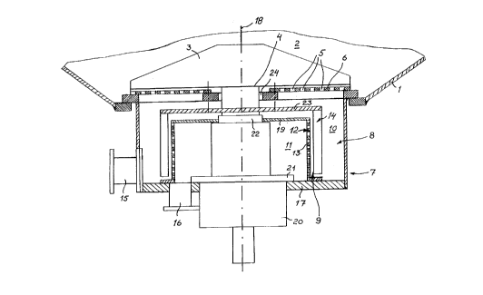
The invention is further illustrated in the following
description by reference to the embodiment shown in the
enclosed drawing. The drawing shows one embodiment of the
pulper according to the invention as a partial cross-section
at the bottom level of the pulper, wherein said screening
unit is connected to the lower part of the pulper.
In the drawing, the pulper housing 1 restricts the feed
chamber 2. The feed chamber 2 accommodates a rotor unit 3 or
corresponding. The rotor unit 3 is attached to the vertical
shaft 4, the drive unit for rotating rotor unit.


CA 02018175 1998-11-02
2~~ 181.'5
3
3 being connected thereto. A screenplate 6 with
perforations 5 is located under the rotor unit 3. As to
the technical solutions concerning the rotor unit 3 and
the perforated screenplate 6 reference can be made e.g.
to the US patent publication 3,889,885. This kind of
rotor units are commonly known in the field and they will
not be explained further in this connection.
There is a space 8 restricted by the housing 7 and
situated on the opposite side of the perforated
screenplate 6 as seen from the rotor unit 3 or
corresponding, to which space the fibre material in the
feed chamber 2 is transferred via screenplate 6 guided by
the rotor unit 3.
According to the invention the space 8 consists of the
screening unit 9. The screening unit 9 consists of the
first partial space 10, the second partial space 11, the
partition wall construction 12, which at least partly
consists of the perforated screenplate 13, and the
cleaning device 14.
The first partial space 10 is in direct connection with
the screenplate 6 which is in connection with the rotor
unit 3. The first space 10 accommodates the discharge
connection unit 15 which is placed on the outer surface
of housing 7, on its lower part.
The second partial space 11 for the accepted portion
consists of a discharge connection unit 16 preferably
placed on the end part 17 of housing 7.
The housing 7 which restricts the space 8 has preferably
a cylindrical form wherefore the centre line 18 of the
cylindrical form is congruent with the centre line of
shaft 4. Screenplate 13 has also a cylindrical form and
it is so arranged that its centre line is congruent with


CA 02018175 1998-11-02
2~l-181'~S
4
the centre line 18 of housing 7. The end part 17 of
housing 7 forms the first end part of the second partial
space 11. The second end part of the second partial space
11 is formed by a closed part 19, which is essentially
parallel with the perforated screenplate 6, of the
partition wall construction 12.
The shaft 4 is fitted to pass through the second partial
space 11 wherefore a bearing unit 20 is disposed on the
outside of the end part 17 of the housing 7 and is
supported by a flange 21 to said end part. The shaft 4 is
provided with a sealing unit 22 by the closed part 19 of
the partition wall construotion 12, the sealing unit
preferably comprising of a combination of a strip-like
and/or a mechanical seal. A supporting structure 23
extending radially from the shaft 4 is attached to the
shaft 4 in the first partial space 10 between the closed
part 19 and the perforated screenplate 6. A cleaning
device 14, extending downwards and comprising of blade-
like elongated form parts, is attached to the end of the
supporting structure 23. The blade-like form parts are
disposed at specific distances on the circumference of
the supporting structure 23. The purpose of the cleaning
device is to keep the perforations of the screenplate 13
unplugged wherefore the form parts move along the
screenplate 13 in the first partial space 10. In this
connection it can be stated that the cleaning device 14
can also be placed on the side of the second partial
space 11 by means of a similar supporting structure as
shown in the drawing either as an alternative or in
addition to the construction shown in the drawing.
The cleaning device 14 and the rotor unit 3 or
corresponding, in the embodiment according to the
invention, are provided with a common drive unit (not
shown) by which the shaft 4 operates both assemblies
moving relative to the pulper. As shown in the enclosed


CA 02018175 1998-11-02
2~ 1~18~.'~S
drawing the cleaning device 14 and the rotor unit 3 or
corresponding are connected to the same shaft 4. The
bearing unit 20 can be provided with a gear reducer.
Shaft 4 is adapted to pass through the perforated
5 screenplate 6. Then an annular slot 24 can be left
between the outer surface of the shaft 4 and the
screenplate 6 which can serve preferably as part of the
perforation of the screenplate 6.

Representative Drawing
A single figure which represents the drawing illustrating the invention.
Administrative Status

For a clearer understanding of the status of the application/patent presented on this page, the site Disclaimer , as well as the definitions for Patent , Administrative Status , Maintenance Fee  and Payment History  should be consulted.

Administrative Status

Title Date
Forecasted Issue Date 2000-01-04
(22) Filed 1990-06-04
(41) Open to Public Inspection 1990-12-05
Examination Requested 1997-01-07
(45) Issued 2000-01-04
Deemed Expired 2009-06-04

Abandonment History

There is no abandonment history.

Payment History

Fee Type Anniversary Year Due Date Amount Paid Paid Date
Application Fee $0.00 1990-06-04
Registration of a document - section 124 $0.00 1990-12-14
Maintenance Fee - Application - New Act 2 1992-06-04 $100.00 1992-06-03
Maintenance Fee - Application - New Act 3 1993-06-04 $100.00 1993-05-20
Maintenance Fee - Application - New Act 4 1994-06-06 $100.00 1994-04-11
Maintenance Fee - Application - New Act 5 1995-06-05 $150.00 1995-05-02
Maintenance Fee - Application - New Act 6 1996-06-04 $150.00 1996-05-15
Request for Examination $400.00 1997-01-07
Maintenance Fee - Application - New Act 7 1997-06-04 $150.00 1997-05-16
Registration of a document - section 124 $50.00 1997-09-04
Maintenance Fee - Application - New Act 8 1998-06-04 $150.00 1998-05-19
Maintenance Fee - Application - New Act 9 1999-06-04 $150.00 1999-05-06
Final Fee $300.00 1999-09-29
Maintenance Fee - Patent - New Act 10 2000-06-05 $200.00 2000-05-30
Maintenance Fee - Patent - New Act 11 2001-06-04 $200.00 2001-05-16
Maintenance Fee - Patent - New Act 12 2002-06-04 $200.00 2002-05-17
Maintenance Fee - Patent - New Act 13 2003-06-04 $200.00 2003-05-20
Maintenance Fee - Patent - New Act 14 2004-06-04 $250.00 2004-05-17
Maintenance Fee - Patent - New Act 15 2005-06-06 $450.00 2005-05-27
Maintenance Fee - Patent - New Act 16 2006-06-05 $450.00 2006-05-24
Maintenance Fee - Patent - New Act 17 2007-06-04 $450.00 2007-05-28
Owners on Record

Note: Records showing the ownership history in alphabetical order.

Current Owners on Record
VALMET CORPORATION
Past Owners on Record
HAUTALA, JOUKO
OY TAMPELLA AB
TAMROCK OY
Past Owners that do not appear in the "Owners on Record" listing will appear in other documentation within the application.
Documents

To view selected files, please enter reCAPTCHA code :


To view images, click a link in the Document Description column. To download the documents, select one or more checkboxes in the first column and then click the "Download Selected in PDF format (Zip Archive)" or the "Download Selected as Single PDF" button.

List of published and non-published patent-specific documents on the CPD .

If you have any difficulty accessing content, you can call the Client Service Centre at 1-866-997-1936 or send them an e-mail at CIPO Client Service Centre.


Document
Description 
Date
(yyyy-mm-dd) 
Number of pages   Size of Image (KB) 
Claims 1998-11-02 4 167
Cover Page 1994-03-02 1 11
Abstract 1994-03-02 1 33
Drawings 1994-03-02 1 22
Claims 1994-03-02 3 98
Description 1994-03-02 5 174
Cover Page 1999-12-15 1 47
Description 1998-11-02 6 219
Cover Page 1993-10-16 1 11
Abstract 1993-10-16 1 33
Claims 1993-10-16 3 98
Drawings 1993-10-16 1 22
Description 1993-10-16 5 174
Representative Drawing 1999-12-15 1 12
Correspondence 1999-09-29 1 26
Prosecution-Amendment 1998-11-02 9 325
Assignment 1990-06-04 6 190
Prosecution-Amendment 1997-01-07 4 156
Prosecution-Amendment 1998-08-07 2 4
Fees 1997-05-16 1 64
Fees 1996-05-15 1 51
Fees 1995-05-02 1 59
Fees 1994-04-11 1 35
Fees 1993-05-20 1 44
Fees 1992-06-03 1 49
Assignment 1997-09-04 7 215