Note: Descriptions are shown in the official language in which they were submitted.
-1-
EXTRUSION FULLER WITR STRIPPER FINGER
Technical Field
The invention relates to extrusion pulling
apparatus and, more particularly, to an extrusion pulling
apparatus having a stripper finger which moves in a
direction transverse to the extrusion axis toward coollrig
and run-out tables to aid the quick removal of the
extruded material from the jaws for a decreased cycle
time.
Baokground of the Invention
One of the on-going goals of extrusion
operations is to decrease the cycle time for each
extrusion operation and thereby increase productivity of
the extrusion equipment. Extrusion pulling apparatus
incorporate lower jaws which move in a direction
transverse to the extrusion axis at the completion of the
pulling cycle to allow for removal of the extruded work
from the run-out table. The extrusion pulling apparatus
then quickly moves back to an initial position to grip a
new portion of the work.
Occasionally the extrusions are dragged off the
run-out tables by the transverse movement of the jaw from
the table. In order to overcome this problem, a fixed
stripper finger has been incorporated in the extrusion
pulling apparatus adjacent the jaw to retain,the extruded
workpiece on the run-out table as the lower jaw is
transversely moved. The fixed stripper finger is
attached to the extrusion pulling apparatus on the side
of the run-out table opposite the cooling table. As the
extrusion pulling apparatus completes its pulling cycle,
the jaws release their grip on the extruded workpiece and
move transverse to the extrusion axis away from the
cooling and run-out table. If the extruded workpiece is
not completely freed from the lower jaw, the extruded
workpiece will ultimately contact the fixed stripper
finger as the lower jaw moves in the transverse
direction. This contact with the fixed stripper finger
and the movement of the jaws causes the workpiece to be
removed from the lower jaws and rest on the run-out table
-2-
~J~'~
(w
for transfer to the cooling table and further operations.
Although the fixed stripper finger effectively
retains the extrusions on the run-out table, the
extrusions are initially positioned on the far side of
the run-out table from the cooling table. It thus takes
some time to move the extrusions across the run-out table
and onto the cooling table. In the meantime, the
extrusions in transit may interfere with the movement of
the new extrusions along the run-out tables and thus slow
the extrusion cycle.
Strippers have also been used for stripping
extruded workpieces from cylindrical mandrels. For
example, the U.S. Pat. No. 2,298,887 to Jongedyk (issued
October 13, 1942) discloses a pair of stripper members
for use in removal of a cylindrical extrusion workpiece
from a corresponding cylindrical mandrel in an extrusion
press operation. The pair of stripper members interact
with each other through an elastic interconnecting
linkage means to allow for adjustment of one stripper
2~ member relative to the other.
SUMMARY OF THE INVENTION
According to the invention, an extrusion
pulling apparatus comprises an extrusion run-out table, a
cooling table, an extrusion pulley, means mounting said
pulley for movement along the run-out table, and means on
the pulley for pushing the work laterally toward the
cooling table from the extrusion axis when the pullet
reaches a release position along the run-out table. The
extrusion pulley comprises a support frame, an upper jaw
which is movable vertically between clamping and release
positions on the support frame and a lower jaw which is
movable laterally between clamping and release positions
on the support frame. The means for mounting the pulley
for movement along the run-out table operates between a
loading position and a release position to pull the work
along an extrusion axis as the extrusion pulley moves
between the loading and release positions.
Preferably, the pushing means on the extrusion
_3_
~~ i~~l~~
pulley for laterally moving the work comprises a finger
mounted adjacent the upper and lower jaws when the jaWS
are in a clamping position. The pushing means further
comprises a guide means mounting the finger above the
lower jaw for linear sliding movement of the finger with
respect to the support frame. The lower jaw and guide
means mounting the finger are both mounted on the support
frame.
Support means mount the lower jaw and comprise
means far mounting the lower jaw support means to the
support frame for vertical movement with respect to the
support frame. The previously discussed guide means
mounting the finger is mounted to this lower jaw support
means. Further, reciprocal means are mounted on the
lower jaw support means for reciprocally moving the
finger with respect to the lower jaw support means.
Means for mounting the lower jaw to the lower jaw support
means for lateral movement with respect thereto can also
be included. This element comprises means for moving the
lower jaw laterally away from the cooling table and means
for moving the finger toward the cooling table as the
lower jaW is moved away from the coaling table. The
finger moving means can include a fluid cylinder.
The invention provides a distinct advantage
over the prior art in that it allows for quicker and more
efficient operation of the extrusion apparatus. The
incorporation of the stripper finger and stripper finger
pushing means decreases the cycle time for each extrusion
pulling operation by removing the workpiece from the
extrusion axis more rapidly. The quicker the workpiece
is transferred to the cooling table and removed for
further processing, the quicker the extrusion pulley can
be recycled for further pulling operations.
BRIEF DESCRIPTION OF DRAWINGS
The invention will now be described in detail
with reference to the accompanying drawings wherein:
FIG. 1 is a perspective view of an extrusion
pulling apparatus incorporating the invention;
-4-
FIG. 2 is a partial sectional end view of the
extrusion pulling apparatus shown in FIG. 1 taken along
lines 2-2 of FIG. 1:
FIG. 3 is a partial sectional view taken along
lines 3-3 of FIG. 2; and
FIG. 4 is a partial sectional view of the lower
jaw assembly taken generally along lines 4-4 of FIG. 2.
DESCRIPTION OF THE PREFERRED EMBODIMENT
Referring to FIG. 1, an extrusion apparatus
comprises an extrusion press 12, an extrusion pullet 14,
a run-out table 16 and a cooling table 22. It is well
known to construct a pulling apparatus wherein a material
to be pulled 18 (FIG. 3) is forced through the extrusion
press 12 and gripped by the extrusion pullet 14. The
extrusion pullet 14 is driven away from the extrusion
press 12 along the extrusion axis A by a suitable drive
means (not shown) and the extruded material 18 is
supported by the run-out table 16. After the extrusion
is completed, the extruded material 18 is transferred
2o from the run-out table 16 to the cooling table 22 for
further processing.
The cycle time for each operation of the
extrusion apparatus 10 can be decreased upon the quicker
removal of the extruded material 18 from the run-out
table 16 onto the cooling table 22. The quicker the
workpiece 18 is removed from the run-out table 16, the
quicker the extrusion pullet 14 can be recycled for
another pull. The workpiece 18 is transferred by a
conveyor means 24 to the cooling table 22 from the run-
out table 16. Conventional conveyor systems for cooling
and run-out table assemblies are described in U.S. Pat.
No. 4,790,167 to Gentry et al. (issued December 13, 1988)
and U.S. Pat. No. 4,507,950 to Elhaus (issued April 2,
1985).
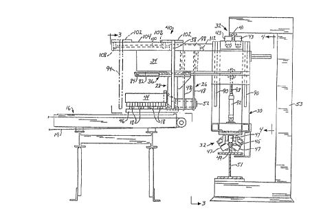
As seen in FIG. 2, the extrusion pullet 14
which is designed to decrease the cycle time for the
extrusion operation comprises a rectangular support frame
30, guide means 32, a lower jaw support frame 34, drive
-5-
means 36 for transverse movement of the pulley jaws,
upper jaw pulley assembly 26, lower jaw pullet assembly
28, an upper jaw 44, a lower jaw 46, a stripper finger
assembly 38, and guide means for 'the stripper finger 40,
The rectangular support frame 30 is mounted to
the guide means 32 for movement of the extrusion pullet
14 along the extrusion axis A. In the preferred
embodiment, the guide means 32 comprises a T-shaped guide
beam 41, a pair of rollers 43 far the T-shaped guide beam
41, a hexagonal guide beam 45, a plurality of rollers 47
for the hexagonal guide beam 45, a rectangular support
beam 49, an I-shaped support beam 51, and a plurality of
C-shaped support members 53. The C-shaped support
members 53 support both the T-shaped guide beam 41 and
the hexagonal guide beam 45. The T-shaped guide beam 41
is fixedly attached to the top portion of the C-shaped
support means 53 and the hexagonal guide beam 45 is
supported on the lower portion of the C-shaped support
member 53 by the rectangular support beam 49 and the I-
shaped beam 51. Fixedly attached to the top of the
rectangular support frame 30 are the two rollers which
are mounted for rolling contact with the T-shaped guide
beam 41. These rollers 43 contact the T-shaped guide
beam 41 on opposite vertical faces of the T-shaped guide
beam 41. The rollers far the hexagonal guide beam 47 are
fixedly mounted to the rectangular support frame 30 and
roll along the hexagonal guide beam 45 on three of the
six surfaces to provide both stability and support for
the extrusion pulley 14.
Slidably attached (discussed below) to the
rectangular support frame 30 for vertical mavement with
respect thereto is the lower jaw support frame 34. In
the preferred embodiment, the lower jaw support frame 34
comprises a rectangular tube which extends horizontally
and perpendicular to the extrusion axis A to a point
above the run-out table 16. Suspended from the lower jaw
support frame 34 is the lower pulley jaw assembly 28.
As seen in FIG. 3, the upper pullet jaw
assembly 26 comprises the upper pulley jaw 44, a fixed
-6-
upper arm 48, a movable lower arm 50, a pivot pin 52, a
crank arm 54, and an upper jaw hydraulic cylinder 56.
The upper pulley jaw assembly 26 is designed so that the
upper pulley jaw 44 is pivotably mounted to the lower jaw
support frame 34. One end of the fixed upper arm 48 is
fixedly attached to the lower jaw support frame 34 and
the other end of the fixed upper arm 48 is pivotably
connected to the movable lower arm 50 by the pivot pin
52. The fixed upper arm 48 provides support fox the
movable lower arm 50 during the pulling operation. The
upper jaw hydraulic cylinder 56 is pivotably mounted on
upper arm 48 through a U-shaped plate 62 and a pivot pin
64. The cylinder 56 has a push rod 60 pivotably attached
to the crank arm 54 which is in turn non-rotatably
attached to the pivot pin 52. Upon retraction of the
push rod 60 of the hydraulic cylinder 56, the movable
lower arm 50 and the upper jaw 44 are moved vertically
from a clamping to a release position. The upper jaw 44
pivots down to clamp onto the workpiece 18 at the
beginning of the extrusion pulling operation and pivots
upward to release the gripping pressure on the extruded
workpiece 18 upon completion of the pulling cycle.
As seen in FIGS. 3 and 4, the lower jaw
assembly 28 is designed to move horizontally in a
direction perpendicular to the extrusion axis A to aid in
the quick and efficient removal of the workpiece 18 from
the extrusion pulley 14. The lower jaw assembly 28
comprises a fixed arm 70, a track,and bearing assembly
72, a hydraulic cylinder 74 and a push rod 82 (FIG. 2).
The track and bearing assembly 72 is mounted on the
underside of the lower jaw support frame 34 and comprises
an upper track 78 and a lower bearing 80 to facilitate
sliding movement of the interlocking tracks. The upper
track 78 is fixedly attached to the lower jaw support
frame 34 and the lower bearing 80 is fixedly attached to
a mounting plate 76 fixed to the top portion of fixed arm
70. Therefore, the mounting plate 76 and lower bearing
80 can slide relative to the lower jaw support frame 34
perpendicular to the extrusion axis A. The track and
_7_
bearing assembly is preferably the type in which the
track 78 has lateral guide flanges which are received in
grooves in the bearing 80. Ball or roller bearings are
mounted between the guide flanges and the grooves. A
suitable bearing structure is a THK LM Guide HSR TYPE
manufactured by THK Go. Ltd. of Tokyo, Japan.
The hydraulic cylinder 74 is fixedly attached
to the underside of the lower jaw support frame 34 by
mounting screws 86. Further, the push rod 82 of the
hydraulic cylinder 74 is fixedly attached to the mount-
ing plate 76 by a mounting bracket 84 (FIG. 2). one end
of the fixed arm 70 of the lower jaw 46 is also fixedly
attached to the mounting plate 76. The other end of the
fixed arm 70 is fixedly attached to the lower jaw 46 by a
plurality of mounting screws 88 shown in phantom lines in
FIG. 4. The fixed arm 70 provides support and stability
for the lower jaw 46.
The lower jaw 46 can move in a direction
transverse to the extrusion axis A through the operation
of the hydraulic cylinder 74 and push rod 82. As the
push rod 82 (FTG. 2) is retracted from the hydraulic
cylinder 74, the mounting plate 76, fixed arm 70 and
lower jaw 46 are moved away from the cooling table 22.
As the push rod 82 is extended, the mounting plate and
lower jaw assembly are returned to a position above the
run-out table 16 as shown in FIG. 2.
Another feature which speeds up the removal of
the workpiece 18 from the extrusion axis A and increases
the extrusion cycle is the stripper finger assembly 38.
As seen in FIG. 4, the stripper finger assembly 38
comprises a stripper finger 94, a track and bearing
assembly 96, a hydraulic cylinder 98, a push rod 100
(FIG. 2), and a stripper finger mounting 102. The track
and bearing assembly comprises a bearing 104 and a lower
track 106 to facilitate sliding motion of the tracks
relative to each other. The lower track 106 is fixedly
attached to the upper surface of the lower jaw support
frame 34. The hydraulic cylinder 98 is also fixedly
attached to the upper surface of the lower jaw support
_g_
frame 34 by mounting screws 112. The stripper finger
mounting 102 is fixedly attached to the bearing 104, the
push rod mounting 108 (FIG. 2), and the stripper finger
94. The stripper finger 94 extends downward to a point
adjacent to the leading edges of the upper and lower jaws
110 while in the clamped position. The track and bearing
assembly 96 is of the same nature as the track and
bearing assembly 72.
During the pulling operation, the stripper
finger 94 is in the retracted state, shcwn in solid lines
in FIG. 2, and the jaws axe above the run-out table 16 as
seen in FIG. 2. At the completion of the pulling cycle,
the upper jaw 44 pivots upward to release the gripping
pressure on the workpiece 18. Thereafter, the stripper
finger 94 and lower jaw assembly 28 work in conjunction
to quickly remove the workpiece 18 from the run-out table
16 to allow fax a quick return of the extrusion puller
14. The hydraulic cylinder 98 of the stripper finger 98
begins to extend the push rod 104, thereby forcing the
stripper finger 94 in a direction toward the cooling
table 22, i.e., to the left as seen in FIG. 2. At the
same time, the hydraulic cylinder of the lower jaw 74
begins to retract the push rod 82, thereby forcing the
lower jaw assembly in a direction opposite the movement
of the stripper finger 94, away from the cooling table
22. Through the opposite motion of these two assemblies,
the stripper finger 94 can quickly contact the workpiece
18, push it away from the extrusion axis, thereby
removing it from the lower jaw 46 and transferring the
workpiece 18 to the cooling portion of the run-out table
16.
As seen in FIGS. 2 and 4 the lower jaw support
frame 34 is slidably mounted on the rectangular support
frame 3o so that the support frame 30 and lower jaw
apparatus 28 can move vertically relative to the run-out
table 16. This movement is accomplished by a sliding
track assembly 9o and hydraulic cylinder assembly 92. The
hydraulic cylinder assembly 92 is mounted at a lower
portion to the support frame 30 and has an extendible
_g_
push rod 93 in the form of a threaded rod which is
secured through nuts 95 to the sliding track 97 which, in
turn, is mounted to the lower jaw support frame 34. The
sliding track assembly 90 allows for sliding movement of
the lower jaw support frame 34 vertically along the
rectangular support frame 30. This sliding movement is
accomplished by the extension and retraction of the push
rod 93 of hydraulic cylinder assembly 92.
The vertical movement of the lower jaw assembly
28, which is accomplished by the track and bearing
assembly 90 of the rectangular support frame 30 and the
hydraulic cylinder 92 of the rectangular support frame
30, is necessary far the proper loading of the workpiece
18 in the upper and lower jaws 44 and 46. As the
workpiece exits the extrusion press 12, the lower jaw
assembly 28 moves vertically upward from its release
state to its clamping state. The pulley 14 then
accelerates along the extrusion line so that the pulley
14 and the extrusion 18 move at the same speed. The
upper jaw assembly 26 then moves downward from its
release state to the clamping state to grip the work-
piece is between the upper and lower jaws 44 and 46.
After sufficient clamping pressure has been exerted, the
extrusion pulley 14 begins the pulling operation from the
force supplied by the extrusion pulley drive. means (not
shown).
The coordinated clamping motion of the upper
jaw apparatus 26 and the lower jaw apparatus 28 is also
suitable for receiving the workpiece 18 from another
extrusion pulley (not shown). Two pulleys may work
together on the same run-out table to increase the
productivity of the equipment as follows: A first pulley
P-1 receives the workpiece from the extrusion press as
described above. Then, the pulley P-1 pulls the
workpiece 18 to a point midway on the extrusion axis A
and transfers the workpiece 18 to a second pulley P-2
which continues the pulling operation for the desired
length of the work. As the second pulley P-2 is
completing the extrusion operation, the first pulley P-1
-10-
can recycle back to the loading position near the
extrusion press 12. When the first pulley P-1 returns to
the extrusion press, it awaits the die line and then
grips the extrusion. It will cut off the extrusion after
it grips the same. The cut-off operation is timed to
correspond to the pulley P-2 reaching the end of its
travel in the pulling cycle. The transfer from one
pulley to the other is accomplished as follows: as the
first pulley P-1 nears the midway point of the extrusion
axis A-A, the second pulley P-2 is aligned behind the
first pulley P-1. The P-2 upper jaw assembly 26 moves
downward into the clamping position while the lower jaw
assembly 28 moves vertically upward to the clamping
position to grip the workpiece 18 at a point behind the
fixst pulley P-1. When sufficient gripping pressure is
applied, the upper and lower jaws 44, 46 of the first
pulley P-1 release their grip and the first pulley P-1
may be recycled while the second pulley P-2 continues the
pulling operation.
While particular embodiments of the invention
have been shown, it will be understood, of course, that
the invention is not limited 'thereto since modifications
may be made by those skilled in the art, particularly in
light of the foregoing teachings. It is, therefore,
contemplated by the appended claims to cover.any such
modification as incorporate those ~eatures which
constitute the essential features of these improvements
within the true spirit and scope of the invention.