Language selection

Search

Patent 2018540 Summary

Third-party information liability

Some of the information on this Web page has been provided by external sources. The Government of Canada is not responsible for the accuracy, reliability or currency of the information supplied by external sources. Users wishing to rely upon this information should consult directly with the source of the information. Content provided by external sources is not subject to official languages, privacy and accessibility requirements.

Claims and Abstract availability

Any discrepancies in the text and image of the Claims and Abstract are due to differing posting times. Text of the Claims and Abstract are posted:

  • At the time the application is open to public inspection;
  • At the time of issue of the patent (grant).
(12) Patent: (11) CA 2018540
(54) English Title: BLASTING DEVICE FOR UNBLOCKING MINE RAISES
(54) French Title: DISPOSITIF DE SAUTAGE POUR DEBLOQUER LES GALERIES MONTANTES
Status: Deemed expired
Bibliographic Data
Abstracts

English Abstract


-8-
Abstract of the Disclosure:
A blasting device for unblocking ore passes,
backfill raises, mine draw points and any other near
vertical raises where rocks or other materials normally
fall freely but may get blocked during use, comprises a
propulsion unit including an air chamber mounted at the
end of a hollow tube and having an inlet for receiving
pressurized air and at least one outlet for allowing
compressed air jets to exit downwardly from the air
chamber to propel the propulsion unit upwardly, a
reservoir mounted on the propulsion unit and adapted to
hold explosive and an igniter, means for feeding
pressurized air into the air chamber through the hollow
tube, and an ignition line connected to the igniter for
igniting the explosive from a distance.


Claims

Note: Claims are shown in the official language in which they were submitted.

-6-
CLAIMS
1. A blasting device for unblocking ore passes,
backfill raises, mine draw points and any other near
vertical raises where rocks or other materials normally
fall freely but may get blocked during use, comprising:
a) a propulsion unit including an air chamber
mounted at the end of a hollow tube and having an inlet
for receiving pressurized air and at least one outlet
for allowing compressed air jets to exit downwardly from
said air chamber to propel the propulsion unit upwardly;
b) a reservoir mounted on said propulsion unit and
adapted to hold explosive and an igniter:
c) means for feeding pressurized air into said air
chamber through said hollow tube: and
d) an ignition line connected to said igniter for
igniting said explosive from a distance.
2. A blasting device as defined in claim 1, further
comprising a plurality of radial rods mounted
circumferentially on said blasting device to keep the
blasting device away from the walls of the raise thus
allowing the device to raise freely along the walls of
the raise.


-7-

3. A blasting device as defined in claim 1, further
comprising a plurality of fins equally spaced around
said tube for allowing aiming of the device at a
particular blockage point and movement of the blasting
device towards the blockage point under the thrust of
compressed air.

Description

Note: Descriptions are shown in the official language in which they were submitted.


2(~18540


Bla~tlng Dev~c- for Unblocking Min- Raises.


This invention relates to a blasting device for
unblocking ore passes, backfill raises, mine draw points
or any other near vertical raises, where rock or other
material fall freely, but which may get blocked during

5 use.
Ore passes, backfill raises, mine draw points or
any other near vertical raises often get blocked during
use and it is always a problem to unblock them as it is
highly unsafe for a miner to work in the vicinity of and

more particularly underneath a blockage area. It is
common practice to unbloc~ mine raises by attachlng
explosive stick~ at the upper end of a string of poles,
bracing the lower end of the string at the base of the
raise and igniting the explosive to blast the rock

blockage. However, working in the area immediately
adjacent to the base of a raise is generally dangerous.
Thus, some raises are never unblocked and this result in
great losses in the mines. ~


.

2(~18540


It is the object of the present invention to
provide a device for unblocking mine raises which
presents a minimum of exposure for the miners.
The blasting device, in accordance with the
present invention, comprises a propulsion unit including
an air chamber mounted at the end of a hollow tube and
having an inlet for receiving pressurized air and at
least one outlet or allowlng compressed air ~ets to
exit downwardly from the air chamber to propel the

propulsion unit upwardly, a reservoir mounted on the
propulsion unit and adapted to hold explosive and an
igniter, means for feeding pressurized air into the air
chamber through the hollow tube, and an ignition line
connected to the igniter for igniting the explosive.
la A plurality of radial rods are preferably mounted
circumferentially around the blasting device to keep
sensitive points of the blasting device away from the
walls of the raise and thUs allow the device to raise
freely along the walls of the raise.
A plurality of fins may be equally spaced around
the tube to allow aiming of the device at a particular
blockage point when such blockage is in a line of sight
and movement of the blasting device towards the blockage
point under the thrust of compressed air.

znlss40


The invention will now be disclosed, by way of
example, with reference to the accompanying drawings in
which:
Figure 1 is a diagram of a raise having a rock or
other material blockage at an intermediate point;
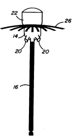
Figure 2 is a side view of a blasting device in

accordance with the present inventionJ
Figure 3 is a section view of the blasting device
of Figure 1: and

Figure 4 is a view of an alternative embodiment of
a blasting device in accordance with the present
invention.
Referring to Figure 1, there is shown a diagram of
a raise 10 having a rock blockage area at an

intermediate point 11. To loosen the rocks, a blasting
device designated generally by reference numeral 12 is
allowed to climb up the walls of the raise under the
thrust o~ compressed air generally provided in a mine
and be blasted to free the rocks.
The blasting device is shown more clearly in
Figures 2 and 3 and comprises a propulsion unit 14
comprising an air chamber mounted at the end of a hollow
tube 16 which acts as a stabilizer and through which is
fed compressed air from a hose 18 as shown in Figure 1.

The air chamber has a plurality of equally spaced air
outlet 20 for allowing air jets to exit downwardly to


2~18540


provide an upward thrust to the propulsion unit. A
reservoir 22 is mounted on the propulsion unit for
containing explosive and a suitable igniter for the
explosive. As shown in Figure 1, an ignition line 24 is
connected to the igniter and is allowed to hang down to
the bottom of the raise for ignition when the blasting
device is in place. A plurality of radial rods 26 made
o~ non-conductive material are egually spaced around the
clrcumference of the device to keep the blasting device
away from the walls of the raise and thus allow the
device to climb freely along the walls of the raise.
In operation, the hollow tube 16 of the blasting
device is connected to the hose 18 and the hose is
itself connected to à compressed air supply 28.
Compressed air is fed through the hollow tube and the
air ~ets from the outlets 20 of the propulsion unit
exert an upward thrust to cause the unit to move up
along the walls of the raise until it contacts the rock
blockage. The ignition line is ignited and the explosive
blasted to unblock the raise.
In order to allow the blasting device to raise
under the regular 100 psi. air pressure normally
provided in the mines, the blasting device is narmally
made of light but strong plastic materials which are
commercially available.

20~8540


Figure 4 illustrates an alternative embodiment of
a blasting device similar to the one shown in Figure 2
which is provided with equally spaced fins 30 around the
hollow tube 16. This allows the device to be aimed at a
S particular blockage point when such point is in a line
of sight. The blasting device then moves towards the
target point under the propelling action o~ compressed
air.
Although the invention has been disclosed with
reference to a preferred embodiment, it is to be
understood that it is not limited to such embodiment and
that other alternative are also envisaged within the
scope of the following claims.


Representative Drawing
A single figure which represents the drawing illustrating the invention.
Administrative Status

For a clearer understanding of the status of the application/patent presented on this page, the site Disclaimer , as well as the definitions for Patent , Administrative Status , Maintenance Fee  and Payment History  should be consulted.

Administrative Status

Title Date
Forecasted Issue Date 1993-07-27
(22) Filed 1990-06-07
Examination Requested 1990-09-07
(41) Open to Public Inspection 1991-12-07
(45) Issued 1993-07-27
Deemed Expired 2007-06-07

Abandonment History

There is no abandonment history.

Payment History

Fee Type Anniversary Year Due Date Amount Paid Paid Date
Application Fee $0.00 1990-06-07
Maintenance Fee - Application - New Act 2 1992-06-08 $100.00 1992-05-22
Maintenance Fee - Application - New Act 3 1993-06-07 $100.00 1993-05-26
Maintenance Fee - Patent - New Act 4 1994-06-07 $50.00 1994-05-25
Maintenance Fee - Patent - New Act 5 1995-06-07 $75.00 1995-06-02
Maintenance Fee - Patent - New Act 6 1996-06-07 $75.00 1996-05-22
Maintenance Fee - Patent - New Act 7 1997-06-09 $75.00 1997-05-12
Maintenance Fee - Patent - New Act 8 1998-06-08 $75.00 1998-06-01
Maintenance Fee - Patent - New Act 9 1999-06-07 $75.00 1999-06-04
Maintenance Fee - Patent - New Act 10 2000-06-07 $100.00 2000-02-24
Maintenance Fee - Patent - New Act 11 2001-06-07 $100.00 2001-04-24
Maintenance Fee - Patent - New Act 12 2002-06-07 $100.00 2002-05-14
Maintenance Fee - Patent - New Act 13 2003-06-09 $100.00 2003-05-01
Maintenance Fee - Patent - New Act 14 2004-06-07 $125.00 2004-04-13
Maintenance Fee - Patent - New Act 15 2005-06-07 $225.00 2005-03-09
Owners on Record

Note: Records showing the ownership history in alphabetical order.

Current Owners on Record
DION, SERGE
Past Owners on Record
None
Past Owners that do not appear in the "Owners on Record" listing will appear in other documentation within the application.
Documents

To view selected files, please enter reCAPTCHA code :


To view images, click a link in the Document Description column. To download the documents, select one or more checkboxes in the first column and then click the "Download Selected in PDF format (Zip Archive)" or the "Download Selected as Single PDF" button.

List of published and non-published patent-specific documents on the CPD .

If you have any difficulty accessing content, you can call the Client Service Centre at 1-866-997-1936 or send them an e-mail at CIPO Client Service Centre.


Document
Description 
Date
(yyyy-mm-dd) 
Number of pages   Size of Image (KB) 
Cover Page 1994-07-09 1 11
Abstract 1994-07-09 1 19
Claims 1994-07-09 2 33
Drawings 1994-07-09 2 28
Description 1994-07-09 5 127
Representative Drawing 1999-07-15 1 2
Correspondence 2003-12-30 1 12
Examiner Requisition 1992-11-17 1 55
PCT Correspondence 1993-07-05 3 105
Prosecution Correspondence 1990-09-07 1 30
Office Letter 1990-11-26 1 18
PCT Correspondence 1991-08-20 1 32
Office Letter 1991-09-06 1 23
PCT Correspondence 1991-10-07 1 23
Office Letter 1991-11-14 1 41
Office Letter 1993-03-24 1 31
Prosecution Correspondence 1993-03-01 3 96
Office Letter 1991-11-14 1 40
PCT Correspondence 1993-05-18 1 21
Office Letter 1993-07-27 1 13
Prosecution Correspondence 1992-11-27 1 29
Correspondence 2007-07-31 1 40
Correspondence 2007-10-16 2 46
Fees 1997-05-12 1 78
Fees 1996-05-22 1 70
Fees 1995-06-02 1 69
Fees 1994-05-23 1 71
Fees 1993-05-26 1 37
Fees 1992-05-22 1 40