Note: Descriptions are shown in the official language in which they were submitted.
20~74
-- 1 --
METAL-AIR 8ATTERY WITH EASILY REMOVABLE ANODES
Backqround of the Invention
The present invention relates to a metal-air battery
consisting of a cell frame and an air cathode attached
onto each face of the frame. An anode is inserted into
the space between the cathodes so that dissolution occurs
on both sides of the anode.
Description of the Prior Art
Prior U.S. Patent No. 3,513,030 discloses a cell
comprising an envelope-shaped air cathode, a replaceable
consumable anode positioned within the envelope of the
cathode, and an electrolyte between the anode and
cathode. Zinc is listed as a preferred anode material,
but aluminum is also mentioned. The electrolyte can be an
aqueous alkali hydroxide, or a "dry" alkali hydro~ide in
which water is added later. Other electrolytes are also
disclosed. A battery, made up of a plurality of these
cells, utilizes end plates and a drive screw mechanism
pressing the cells together. The anodes are inserted into
the envelope cathodes through openings at the top of the
envelope cathodes. The openings and anodes have
2~ 6~
cooperating surfaces which bear against each other.
However, aqueous alkali hydroxides are known wetting
agents. Even if the opening and anode cooperating
sur~aces are machined to very close tolerances, the end
plates and drive screw mechanism appear to be necessary to
press the opening and anode cooperating surfaces together
in an attempt to seal the openings. No seal which is
effective without the use of a mechanism such as end
plates and a drive screw and/or close tolerance machining
is disclosed.
Prior U.S. Patent No. 3,518,123 discloses a structure
which is similar to that of U.S. Patent No. 3,513,030. In
U.S. Patent No. 3,518,123, the cell includes a reservoir
in communication with the electrolyte chamber arranged to
replenish electrolyte or water lost by transpiration of
water vapor through the hydrophobic member of the cell
cathode. In this patent, as with U.S. Patent No.
3,513,030, no effective seal sealing the anode within the
envelope cathode opening is disclosed.
Prior U.S. Patent No. 3,960,600 discloses an envelope
cathode. A removable anode fits within the envelope
cathode. Wrappings around the anode retain an
electrolyte. A handle on the anode facilitates removal of
the anode. The anode is locked into position in the
envelope cathode by negative terminals which fit into
jacks on the side of the envelope cathode. An O-ring in
the anode top seats the anode top within an opening in the
envelope cathode. Through experience it has been
deter~ined that O-rings can re~uire extremely fine
tolerances and high sealing forces to be an effective seal
in such applications against leakage of an aqueous alkali
hydroxide.
U.S. Patent No. 4,560,626 discloses a metal/air
battery which comprises a housing having electrolyte
2~86~
inlets and outlets~ The housing on the inside supports a
plurality of anodes and pairs of cathodes on opposite
sides of each anode. Seals between the cathodes and
housing walls direct the flow of electrolyte into the
spaces between the anodes and cathodes. Means are
provided for removing the anodes from the housing. There
is no disclosure of a means for anode current collection,
nor of openings in the housing into which the anodes are
seated.
British Patent No. 1,223,127 discloses a plurality of
cell frames. Air permeable cathode surfaces are affi~ed
to opposite sides of the frames. A plate-like anode is
inserted between the cathodes. A handle is provided on
the anode for removing it. The anode has separator paper
impregnated with electrolyte applied to opposite sides of
the anode. The patent has no disclosure concerning a
means for sealing the anode within the cathode frame.
SummarY of the Invention
The present invention resides in a metal-air battery
consisting of one or more cells. Each cell comprises a
cell frame. An air cathode is attached to each face of
the frame. The frame has an access opening. An anode
blank comprises a consumable end which is inserted through
said access opening into the space between the cathodes.
An exposed end on the anode blank protrudes from the
access opening and can be grasped for replacement of the
anode blank through said opening. The anode blank
comprises a labyrinth seal which is molded directly onto
the anode blank between said consumable end and said
exposed end sealing said access opening.
Preferably, the labyrinth seal is an elastomeric
2 0 1~
rubber material which is vulcanized directly onto the
anode blank. The seal has a cross-section in which a main
body portion presses against the anode blank and a
plurality of lobes press against the frame opening. The
lobes can be tapered in a manner which not only resists
removal of the anode blank from the access opening but
also enhances the sealing characteristics of the labyrinth
seal.
In a battery which comprises a plurality of cells,
each cell anode exposed end preferably comprises a contact
edge which is the anode electrical contact. Each cell
comprises a cathode bus which is disposed to one side of
the anode contact edge. The anode contact edges and
cathode buses all lie in the same plane. A plurality of
contact plates bridge the gap between the anode contact
edge of one cell and the cathode bus of an adjacent cell,
thus connecting the cells in-series.
An elongated inter-electrode buswork is removably
attached to the battery. The contact plates are
positioned in spaced-apart relationship longitudinally
along the buswork. Alternatively, the contact plates are
individual shaped jumper bars engaging the anode contact
edge of one cell and the cathode bus of an adjacent
cells. If desired, the cells can be connected in parallel.
Brief Description of the Drawinqs
Further features of the present invention will become
apparent to those skilled in the art to which the present
invention relates from reading the following specification
with reference to the accompanying drawings, in which:
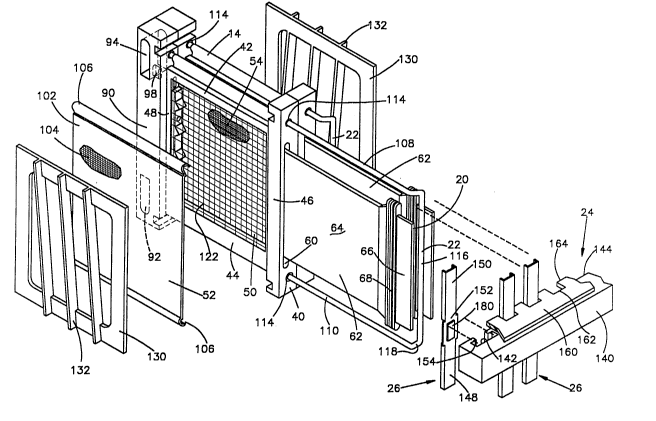
Fig. 1 is a partially exploded view of a pair of
side-by-side cells of the battery of the present invention;
2 !0 1 8 ~ ~ 4
-- 5
Fig. 2 is a plan view of a battery of the present
invention;
Fig. 3 is an elevation side view of the battery of
Fig. 2;
5Fig. 4 is a section elevation view of a portion of an
assembled cell taken along line 4-4 of Fig. 2;
Fig. 5 is a section view taken along line 5-5 of Fig.
4;
Fig. 6 is a section view taken along line 6-6 of Fig.
4;
Fig. 7 is an elevation side view of the battery of
Fig. 2 showing the electrolyte circulation system for the
battery;
Fig. 8 is an elevation view of a cathode/anode
separator for the battery cell of the present invention;
Fig. 9 is a section view taken alonq line 9-9 of Fig.
8;
Fig. 10 is a partial section view of an anode and
labyrinth seal molded to the anode taken along line 10-10
of Fig. 11;
--Fig. 11 is an elevational side view of an anode of the
present invention;
Fig. 12 is a plan view of the anode of Fig. 11;
Fig. 13 is an enlarged perspective view of an interbus
contact plate of the present invention;
Fig. 14 is an enlarged partial section view of the
cell of Fig. 4 showing a cathode bellows in accordance
with the present invention; and
Fig. 15 is an end view of an intercell connector
useful in the alternative to the interbus contact plate of
Fig. 13.
20~8~7~
Description of a Preferred Embodiment
Figs. 2 and 3 illustrate a battery 12 of the present
invention. The battery comprises a plurality of cells 14
in side-by-side relationship. The battery has a cathode
end 16 and an anode end 18.
In the embodiment shown in Figs. 2 and 3, the battery
has ten cells 14. Each cell comprises an anode contact
edge 20 (Fig. 3) and a cathode bus 22 (Figs. 2 and 3),
which preferably has at least general "U-shaped"
configuration as shown in Fig. 1. An external buswork 24,
to be described in more detail further hereinbelow,
comprises a plurality of interbus contact plates 26 (Fig.
3). The contact plates 26 electrically bridge the gap
between the cathode bus 22 of one cell and the anode
contact edge 20 of an adjacent cell, thus connecting the
cells in-series.
The battery has an electrolyte inlet 28 and an
electrolyte outlet 30 by which electrolyte is circulated
into and out of the cells 14. Air fans 32 are provided
for inducing the flow of air through inter-cell spaces,
between adjacent cells 14, into the air cathodes, in a
manner to be described. The use of air fans 32 is
optional.
Details of the cells 14 are shown in Figs. 1 and 4-6.
In Fig. 1, for purposes of illustration, two cells in
side-by-side relationship are shown.
Each cell 14 comprises a frame 40 somewhat in the
shape of a window frame. The frame comprises top and
bottom walls 42 and 44 and side walls 46 and 48. The
frames 40 are made of a machinable or moldable plastic
that is resistant to electrolyte such as acrylonitrile -
butadiene - styrene (ABS) resins or chlorinated polyvinyl
chloride (CPVC) resins and including polypropylene,
201867~
although the use of other materials is contemplated. In
practice, where the battery comprises a plurality of
cells, as shown in Figs. 2 and ~, the cel~s 14 are held
together by welding or gluing the frame 40 of one cell 14
on its walls 42, 44, 46 and 48, to the frame walls 42, 44,
46 and 48 of adjacent cells 14. The top, bottom and side
walls of the frame 40 define a rectangular-shaped
electrolyte chamber 50. The frame is double-faced with
air cathodes 52, 54 glued or otherwise fastened onto each
face. The cathode 52 on the side of the frontmost cell in
Fig. 1 is substantially fully visible. The air cathode 54
on the opposite face of the frontmost cell in Fig. 1 is
partially visible through the electrolyte chamber 50.
In Fig. 1, which is a partially exploded view of two
cells 14, the frontmost air cathode 52, as viewed in Fig.
1, is shown spaced from the frame 40. This is for the
purpose of illustration. In actual practice, the cathode
52 is affixed to the frame walls 42, 44, 46 and 48 as
shown in Figs. 4, 5 and 6.
Each cell frame 40 has an elongated vertically
extending frame opening 60 (Fig. 1) formed in side wall
46. The opening 60 is in co~munication with the
electrolyte chamber 50. The opening is sized to receive a
plate anode 62 plus a seal 68. The anode 62 is inserted
through the opening 60 into the electrolyte chamber 50 so
that it is between the air cathodes 52, 54. In Fig. 1,
both of the plate anodes 62 are shown withdrawn from the
electrolyte chambers 50 of the two cells 14, for the
purpose of illustration.
Details of the plate anode 62 are shown in Figs. 10,
11 and 12. As shown in Fig. 11, the anode is essentially
a rectangular plate with oppositely facing planar surfaces
61, 63. The plate anode ha~ a consumable end 64 and a
hand-grasping, or exposed, end 66. The dimensions of the
2`~18~
anode plate are sufficient so that when the consumable
end 64 is inserted within the electrolyte chamber 50, the
hand grasping end 66 protrudes from the chamber and is
exposed permitting the plate anode 62 to be withdrawn from
the chamber 50.
As shown in Fig. 10, the hand grasping end 66 can be
thinner in cross-section between the opposed planar
surfaces 61, 63 than the consumable end 64. A seal 68 is
interposed between the hand grasping end 66 and the
consumable end 64.
In the embodiment illustrated, the hand grasping end
66 also functions, by means of edge 20, as the anode
contact, in a manner to be hereinafter described. It is
to be understood that the hand grasping end 66 may be
tabbed or slotted or configured in other similar manner to
assist manual insertion of the plate anode 62 through the
frame opening 60 and into tight contact therewith. To
provide the greatest amount of the plate anode 62 for
contact with electrolyte, the hand grasping end 66
supplies only from about 5 to about 30 percent of the
length of the plate anode 62. Preferably, for best
efficiency and economy overall for the battery, such hand
grasping end supplies about 10-25 percent of the plate
anode 62 length.
The anode 62 can be comprised of any metal
conventionally employed in a metal-air battery. E~amples
of metals which have been used are aluminum, zinc, iron,
beryllium, cadmium, magnesium, lithium and lead as well as
alloys and intermi~tures of the same. A preferred metal
in the practice of the present invention is a high
performance, aluminum alloy having low polarization and
low parasitic corrosion values. Such alloys are known and
are disclosed, by way of e~ample, in U.S. Patent No.
3,379,636, in U.S. Patent No. 4,751,086, and in patents
2~1867~
g
cited therein. It is possible, by suitably alloying the
aluminum, to obtain very low corrosion current values, for
instance, ten (10) milliamps per square centimeter. The
disclosures of U.S. Patents Nos. 3,379,636 and 4,751,086
are incorporated by reference herein.
Although it is contemplated that other electrolytes
can be used, e.g., saline electrolyte, a preferred
electrolyte for use in the present invention is an aqueous
solution of an alkali hydroxide, such as sodium hydroxide,
potassium hydroxide, or caustic mi~tures containing the
same. However, an aqueous solution of an alkali hydroxide
has good surface wetting properties and is capable in many
applications of leaking past imperfect seals.
The anode seal 68 is an important aspect of the
present invention. It is dimensioned to fit within the
frame opening 60 in the frame side wall 46 sealing the
opening so as to prevent electrolyte from exiting the
cell. This anode seal also protects the portion of the
anode under the seal where the anode is at open circuit
and therefore susceptible to corrosion. The anode seal 68
- is of the labyrinth type having lobes, e.g., the three
principle lobes 70, 72 and 74 (Figs. 10 and 11) which
press against opening 60. These lobes concentrate the
sealing force and provide a tortuous path for hindering
the flow of electrolyte past the anode seal 68 to the
outside of the cell. The lobes 70, 72, and 74 have a
resilient tapered cross section, as shown in Fig. 10.
Thus, they concentrate the force of the lobe against the
opening 60 on a small area at the apex of each lobe. This
provides high sealing force without a large overall
compressive force.
The taper from the apex of each lobe is accentuated in
the direction inwardly toward the consumable end 64 of
the plate anode. This functions to reduce the amount of
~Q~ 67~
-- 10 --
force which is required to press the anode blank 62 into
the frame opening 60. The taper also functions to resist
anode removal and lock the anode in place when the
anode/seal assembly is pressed down into the cell frame.
The seal 68 is preferably vulcanized directly onto the
anode blank 62. This provides an intimate seal between
the anode surfaces 61 and 63 and the seal 68. Preferred
elastomeric rubber materials are neoprene and
ethylene-propylene-diene-monomer (EPDM), which are stable
to caustic electrolytes. The seal preferably has a low
hardness, for instance about 40 durometer.
When the plate anode 62 is inserted within the
electrolyte chamber 50, it seats along its innermost edge
76 against an anode gasket 78 (Fig. 5). The anode gasket
78 fits inside of the electrolyte chamber 50 against side
wall 48. The gasket 78 is provided with spaced lobes 80.
The plate anode 62, in seating against the anode 78,
presses against the lobes 80 which hold the anode plate
edge 76 slightly spaced from the surface 82 of the
gasket. The lobes 80 provide a high, localized force
against the anode plate edge 76 and serve three
functions: (i) they serve as a stop for the innermost
edge 76 of the plate anode 62 centered between the air
cathodes 52, 54; (ii) serve to seal the electrolyte within
the electrolyte chamber 50; and (iii~ to position the
anode 62 so that the anode e~posed contact edges 20 lie in
essentially the same plane.
Referring to Figs. 1 and 5, the cell frame side wall
48 comprises an enlarged section 90 which contains a lower
electrolyte inlet manifold 92 and an upper electrolyte
outlet manifold 94. The manifolds 92, 94 e~tend
transversely through the section 90. Thus, the inlet
manifold 92 of one cell connects with the inlet manifolds
92 of adjacent cells, i.e., cells on opposite sides of the
2~186~
-- 11
cell shown in Fig. 5. Correspondingly, the outlet
manifold 94 connects with the outlet manifolds 94 of the
adjacent cells on the opposite side of the cell shown in
Fig. 5. The inlet manifold 92 of the endmost cell at the
anode end 18 of the battery (Fig. 3) connects with
electrolyte inlet 28 (Fig. 3), and the outlet manifold 94
of the endmost cell at the anode end 18 of the battery
connects with electrolyte outlet 30.
Each inlet manifold 92, of each cell, communicates
with the cell chamber 50 through an electrolyte inlet
orifice 96 (shown in Figs. 4, 5 and 6). Each outlet
manifold 94 of each cell communicates with the electrolyte
chamber 50 through an outlet port 98. As shown in Fig. 5,
the outlet port 98 is much larger in diameter than the
inlet orifice 96. The purpose of the small diameter of
the inlet orifice 96 is to reduce shunt currents within
the cell. The larger diameter of the outlet port 98
establishes only a slight internal pressure of electrolyte
within each electrolyte chamber 50.
Each air cathode 52, 54 is fastened to the cell frame,
such as by means of a caustic resistant epoxy cement or
the like, e.g., a silicon adhesive. One suitable adhesive
is an aluminum filled epoxy cement marketed by Devcon
Corporation under the trademark "Devconn. The air
25 cathodes 52, 54 can also be sealed to the frame 40 by
means of a gasket. Suitable gasket materials are the same
as those given for the anode seal 68, e.g., neoprene or
EPDM. ln general, it is contemplated that any air cathode
which can be employed in an aluminum-air battery will be
serviceable for use herein.
Details of a preferred high performance air cathode
suitable for use in the present invention are disclosed in
prior Patent No. 4,756,980 assigned to the assignee of the
present application. The disclosure of Patent No.
2 ~ 6 J7 ~
4,756,980 is incorporated herein by reference. The air
cathodes disclosed in Patent No. 4,756,980 comprise a
thin, single layer of catalyzed carbon particles, in
admixture with 10-50 weight percent of a hydrophobic
polymeric binder containing a fluorocarbon polymer.
Either or both the front or back flat surface of the sheet
has pressed into it a foraminous current-conductive metal
mesh or screen. ~n the embodiment illustrated, in Fig. 1,
the air cathode 52 is shown schematically as a sheet 102
of a layer of carbon particles in admixture with a
hydrophobic binder and an outer foraminous metallic
current collector screen 104 embedded in the carbon/binder
layer. The metal screen is exposed to the sheet surface
but is embedded in the surface. The metal screen is then
sintered to the sheet at high temperature. Materials
suitable for cathode screens are silver plated copper
wire, preferably copper wire which is nickel plated with a
silver plate top layer.
The sheet of catalyzed carbon particles and
hydrophobic polymeric binder has an open, porous
construction receptive to the flow of air but at the same
time one that is impermeable to the flow of aqueous
electrolyte into the sheet pores. The metal screen gives
the sheet mechanical strength and also functions as a
metallic current collector. For imparting even more
strength to the air cathode, the cathode can be "double
gridded" as disclosed in Patent No. 4,756,g80, with metal
screen on both sides.
Another especially suitable high performance air
cathode is disclosed in U.S. Patent No. 4,615,954, also
assigned to the assignee of the present application. This
air cathode comprises at least two bonded composite
layers, one of which is a form-stable conductive wet
proofing layer, while the other is a thin-active layer
2~6~
- 13 -
containing active carbon particles and having a high
internal surface area, e.g., more than 1,000
meters2/gram. The disclosure of this patent is also
incorporated by reference herein.
In the embodiment illustrated in Figs. 1 and 4, 5 and
6, the foraminous metal screen 104 has a height
dimensioned so that it extends beyond the confines of the
frame top and bottom walls 42, 44, in upper and lower
contact tabs 106 (Figs. 4 and S). The cathode bus 22 is
in the shape of a handlebar with legs 108, 110, which may
be glued, with an epoxy glue or the like, or gasketed,
into alignment holes 114 in the cell frame 40. In the
embodiment shown in Fig. 1, the cathode bus 22 of the
frontmost cell 14 is shown in a position substantially
withdrawn from holes 114 of the cell frame 40, whereas the
bus 22 of the rearmost second cell 14 is shown in a
position inserted into the alignment holes 114 of the cell
frame 40.
Figs. 4 and 5 show connection of the cathode contact
tabs 106 to the bus legs 108, 110. As shown in Fig. 4,
- the contact tabs are wrapped around the bus legs 108, 110
and can be metallically fastened, e.g., brazed or
soldered, or mechanically fastened, e.g., clipped, to the
bus legs to provide good current contact.
As shown in Fig. 1, each cathode bus 22 comprises an
intermediate, or "post~, section 116 between legs 108, 110
which is offset, by bends 118, slightly to one side of the
plane defined by the bus legs 108, 110. Thus the bus legs
108,110 and anode contact edge 20 of one cell can be at
least substantially in the same plane, but the bus
intermediate section 116 for that cell is offset from such
plane. In the embodiment illustrated, the bus
intermediate section 116 of the frontmost cell 44 is
offset rearwardly so that the intermediate, or center,
2~18~7~
- 14 -
section 116 is parallel to and adjacent the anode contact
edge 20 of the adjacent rearward cell. When all of the
cathode buses of all the cells 14 are inserted ~ully
within the alignment holes 114, all of the bus
S intermediate sections 116 lie in essentially the same
plane, one which is parallel to the side of the battery.
The anode contact edges 20 also lie essentially in this
same plane. It is preferred that the cathode bus 22 be of
a metal whose oxide is electronically conductive or plated
with such a metal, e.g., tin plated copper or silver
plated copper.
Each cell 14 comprises a pair of separators 122, shown
in detail in Figs. 8 and 9, between the cell plate anode
62 and the cell air cathodes 52, 54. The purpose of the
separators 122 is to maintain a gap between the plate
anode 62 and the air cathodes 52, 54. The separators 122
have an open mesh construction and are of a flexible
plastic material, such as polypropylene, resistant to
electrolyte. The mesh construction comprises a plurality
of thin spaced-apart horizontal and vertical strands 126
with thickened nodules 124 at the intersections of the
strands. The nodules maintain the desired anode/cathode
gap separation, whereas the strands, having a nominal
thickness much less than the thickness of the nodules,
permit the flow of electrolyte in the areas between the
cell anode 62 and air cathodes 52, 54.
Referring back to Fig. 1, each air cathode 52, 54
comprises a cathode support frame 130, made of the same
material as frame 40. The support frame can be glued onto
the air side of the cathode 52, 54 around the perimeter of
the cell frame 40 using a caustic resistant epoxy cement
or fastened by similar means. The support frame 130 is
provided with ribs 132 which prevent bowing of the air
cathode during hydraulic upset and also give mechanical
20~8~4
-- 15 --
support to the cathode glue joints by eliminating shear
~orce generation.
As shown in Fig. 1, the ribs 132, for the air cathode
frame 130 facing outwardly are angled slightly with
respect to the sides of the frame 130. The ribs 132 of
the cathode support frame 130 facing rearwardly, as viewed
in Fig. 1, are differently angled. In general, as shown
in the figure, such different angles can be at least
substantially equal but opposite. Thus, the ribs 132 of
one cathode support frame 130 engage but do not mesh with
those of the cathode support frame 130 of the facing
cathode of an adjacent cell. In this way, interspacing
between the air cathodes of adjacent cells is maintained
for adequate flow of air into the air cathodes.
Preferably, the cell operates at a low internal
electrolyte pressure. This requires very low external air
pressure to balance the internal electrolyte pressure.
Thus, the cells can be run at, or slightly above, ambient
air pressure. A slight pressure above ambient air
20 pressure presses the cathode towards the anode due to the
differential pressure in favor of the air side. This
maintains the desired anode/cathode gap and allows
practical operation at low air pumping~compression costs.
It may be desirable to dimension the component parts
25 so that a very thick plate anode 62, for instance about
0.5 inch, is disposed within the cell electrolyte chambers
50. In such instance, the cathodes 52, 54 can be made
movable so that they move towards the anode 62 to maintain
anode/cathode gap as the anode dissolves. An example of a
30 suitable mechanism for doing this is a me~al bellows 134
such as shown in Fig. 14. The metal bellows 134 is in the
shape of a window frame with a flat inner surface 135
which is secured to the air cathode 52, 54. The flat
surface 135 extends around the entire periphery of the air
201867~
-- 1~
cathode 52, 54 and is sealed to the air cathode 52, 54, as
by extending over the top of the air cathode 52,54 and
crimping, or by means such as soldering or brazing. The
bellows 134 has an accordion shaped section 136 connected
to surface 135. The section 136 also extends around the
entire periphery of the air cathode 52, 54, having the
same configuration for the entire periphery as shown in
Fig. 14. A tab 137 extends outwardly (relative to the
cathode 52, 54) from the accordion section 136. The tab
137 extends completely around the periphery of the cathode
52, 54 and is sealed for the entire periphery in area 138
to the cell frame 40, also using a caustic resistant epoxy
cement or similar means. In this way, the metal bellows
134 seals the electrolyte chamber 50 against leakage of
lS electrolyte from the chamber S0 in the area of the air
cathodes 52, 54.
The metal bellows 134 is preferably made of a metal
foil, the bellows folds in section 136 and other folds in
the bellows being formed by crimping or other similar
forming means. In the embodiment of Fig. 14, the flat
inner metal surface 135 is electrically connected, for
instance by brazing or soldering, to the current collector
screen of the air cathode 52, 54 around the entire
periphery of the cathode 52, 54. This may be in addition
to being sealed to the air cathode 52, 54, as where
crimping over the cathode is used. The outwardly
extending tab 137, at the opposed upper and lower ends of
the metal bellows 134, has formed e~tensions 139 whicn
e~tend around the cathode bus legs 108, 110. The
extensions 139 are electrically connected to the cathode
bus legs 108, 110 in a way effective for the flow of
electrical current, for instance by brazing, soldering, or
clipping. In this way, current collected on the cathode -
collector screens is transmitted via the metal bellows 134
2~18~7~
- 17 -
to the cathode bus legs 108, 110. An exemplary metal for
the inner metal surface 135, bellows 134, tab 137 and any
extensions, e.g., the extension 139, is a silver or nickel
foil.
In operation, the metal bellows 134 is expandable and
functions to allow a range of cathode movement as well as
provide electrical contact between the air cathode 52, 54
and bus 108, 110. As the anode 62 is consumed, a positive
air pressure indicated by arrow 141 moves the air cathode
52, 54 in the direction of anode 62. Spacing between the
anode 62 and cathode 52, 54 is maintained by the spacers
of Figs. 8 and 9 (not shown in Fig. 14).
Details of the inter-electrode buswork 24 are
disclosed in Figs. 1, 13 and 15. The inter-electrode
buswork disclosed connects the battery cells in series.
It is understood that the battery cells can also be
connected in parallel if desired, as discussed in more
detail hereinbelow.
The inter-electrode buswork 24 comprises an elongated
terminal block 140 (Fig. 1). The terminal block 140 is
--- made of a dielectric material such as ABS. The terminal
block has a plurality of slots 142 which are spaced along
a face 144 of the terminal block. For a battery with ten
cells, there are ten slots 142.
Each slot 142 receives an electrically conductive,
e.g., copper, interbus contact plate 26 (Fig. 13) or
intercell bus connector 200 (Fig. 15). For purposes of
convenience, reference will generally be made hereinafter
only to the interbus contact plate 26 for securing in the
buswork 24. But it is to be understood that the buswork
24 can be made to accommodate the intercell bus connectors
200 in place of the contact plates 26. Because of this
interchangeability between the plates 26 and connectors
200, where the use of the term "contact plate(s)' is used,
20186~
- 18 -
generally hereinafter (and not, for example, to refer to
the specific design of the plate) it is to be understood
to also mean ~intercell bus connector." In Fig. 1, the
frontmost contact plate 26 is shown in an e~ploded
position removed from slot 142, to show details of the
plate 26 and slot 142. Each interbus contact plate 26 is
an elongated metallic current-conducting member having
upper and lower contact portions 148, 150 and a center
portion 152, as shown in Figs. 1 and 13. The interbus
contact plates 26 are positioned in the slots 142 so that
they are oriented at right angles to the longitudinal a~is
of the terminal block 140. Each slot 142 is provided with
lips 154 which partially close the slot openings. The
center portion 152 of each contact plate 26 comprises
outwardly extending flaps 156 ( Fig. 13). The lips 154
(Fig. 1) engage the flaps 156 (Fig. 13) and serve to
prevent removal of the contact plates 26 through the
openings of slots 142.
The terminal block 140 has upper and lower retainer
plates 160 sectlred thereto. Only the upper retainer plate
160 is visible in Fig. 1. The retainer plates are made of
a dielectric material such as ABS and have slots 162
formed along one edge 164 thereof. The slots 162
correspond with slots 142 of the terminal block, e~cept
that the slots 162 are sized to accommodate only the
narrower upper and lower portions 148, 150 of the interbus
contact plates 26. In this way, the retainer plates 160 -
engages flaps 156 and function to keep the interbus
contact plates 26 from sliding endwise from the terminal
block slots 142.
Each interbus contact plate 26 is U-shaped in cross
section, in upper and lower portions 148, 150, with
flanges 166 (Fig. 13). The width dimension of the
portions 148, 150 is such that when the inter-electrode
201~&~
-- 19 --
buswork 24 is placed up against the side of the battery,
as shown in Figs. 3 and 6, each interbus contact plate 26
bridges the gap between the anode contact edge 20 of one
cell and the cathode bus 22 of an adjacent cell, at its
intermediate section 116, making contact with each
component. In Fig. 6, this cathode bus 22 of the adjacent
cell is shown substantially in phantom, as is the
intercell buswork. By such contact plate 26, contact edge
20 and cathode bus 22 connection, current is conveyed in
series through the battery.
In Fig. 15, there is depicted in cross-section, an
elongated intercell bus connector 200 that is of the
spring clip type. The bus connector has a generally
"U-shaped" center section 202 having first and second legs
203,207. The first leg 203 not only forms a portion of
the central U-shaped section, but also extends through a
bend 204 and an opposite leg 205 to form a hairpin
section. The opposite leg 205 terminates in an opening
flange member 206. The U-shaped center section 202 from
the second leg 207, e~tends into an open curved portion
208 which extends into and terminates at a flange member
209. In use, the U-shaped center section second leg 207,
curved section 208 and opposite leg 203, will clamp onto
the intermediate section 116 of a cathode bus 22. Then
the hairpin portion of the intercell bus connector 200
slips onto the edge 20 of a plate anode 62. The design of
this intercell bus connector provides, principally through
the center U-shaped section 202 flexural tolerance,
together with strength. The U-shaped section can serve as
a lever arm for providing the tolerance needed to
facilitate ease of applying the connector for connecting
anode and cathode. The intercell bus connector 200 will
be a metallic connector such as of standard spring copper
or of copper beryllium alloy.
2 0.1~&6,7`~
- 20 -
Parts of the circuitry of the battery 12 comprise the
battery cathode terminal 168 (Fig. 3) and the battery
anode terminal 169 (Fig. 3), which can each be of tin
plated copper. As shown in Fig. 3, the cathode terminal
S 168 is fastened, for instance by soldering or brazing, to
the cathode bus 22 of the endmost cell 14 at the cathode
end 16 of the battery. The anode terminal 169 is
connected into the battery circuit by means of an interbus
contact plate 26 in electrical contact with an anode
contact edge 20 of an endmost cell 14 at the anode end 18
of the battery.
If desired, the cells can also be connected in a
monopolar (in parallel) arrangement. This can be done by
modifying the inter-electrode buswork 24 terminal block
140 to jumper the anodes together and separately jumper
the cathodes together. This obviates the need for the
interbus contact plates 26. It is however contemplated to
connect each cell stack in series and to then connect
several stacks together in parallel, if parallel
arrangement is desired.
As shown in Fig. 2, the battery has clamps 170, 172 at
opposite ends. These clamps engage hooks 174, 176 at
opposite ends of the inter-electrode buswork 24 and serve
to hold the buswork 24 against the side of the battery.
Thus, the cells of the present invention can be connected
in-series by a very simple connect. Removing the
inter-electrode buswork 24 is accomplished by a very
simple disconnect; simply disengaging the clamps 170, 172
from hooks 174, 176. The clamps 170,172 and hooks 174,176
can be made of any economical and rugged metal, e.g.,
nickel or steel.
Removal of the inter-electrode buswork 24 provides
ready access to the anode hand grasping ends 66,
permitting simple removal and replacement of the anodes in
2 0 ~ 8 ~ 7 ~
- 21 -
the cells 14.
In the embodiment shown in Fig. 1, a compressible
rubber gasket 180, e.g, of EPDM, is inserted between each
interbus contact plate 26 and terminal block 140. The
rubber gasket 180 functions to provide a compressive force
of the interbus contact plate against the anode contact
edge 20 and cathode bus 22 for good electrical contact,
and provides tolerance relief from bus-to-bus.
Instead of using an inter-electrode buswork as shown
in Figs. 1 and 13, it may be desired to connect the
multiple cells 14 by means of individual clips or jumper
bars. These jumper bars have a "U~-shaped configuration,
similar to the end configurations of contact plates 26, so
as to bridge the gap between the anode contact edge 20 of
one cell and the cathode bus 22 of an adjacent cell.
Alternatively, the individual jumper bars may have a
modified "W~-shaped configuration in which the two slots
in each jumper bar are formed to expand and snap onto the
anode contact edge 20 of one cell and onto the cathode bus
22 of an adjacent cell. This provides better contact and
- a more secure engagement of each jumper bar with the anode
contact edges 20 and cathode buses 22.
Each cell frame 40 comprises an inwardly oriented slot
182 (Fig. 5) at each of the four corners of the frame 40.
The four slots 182 are formed to extend laterally in the
frame so that the slots 182 of one cell are aligned with
those of the adjacent cells. In this way, the battery of
the present invention can be provided with upper and lower
plates 184, 186 (Figs. 4 and 5), made of ABS or the like,
which define an air chamber embracing the cells. Air is
fed into a common entrance manifold (not shown) and
allowed to freely escape through a common discharge port
(not shown). This air chamber containment is used such as
when it is desirable to pressurize the air side, or when
2018~6~7~
the the cell is run on oxygen or air scrubbed to remove
carbon dioxide, or when the chamber is pressurized to move
the cathodes 52, 59 toward the anode when the cathodes 52,
54 are mounted on a metal bellows.
Alternatively, the battery of the present invention
can be run without air containment, that is without a
physical air chamber, in which case, air movement on the
air side of the cathodes can be fan assisted by fans 32.
The fans 32 can be mounted on the upper plate 184, which
would be suitably apertured to accommodate the air flow,
or otherwise mounted above the cells. It is to be
understood that it is contemplated that the battery will
be run with any of the substituents which can be employed
for a battery of this type, for example air or oxygen, and
including such as have been scrubbed of carbon dioxide.
As shown in Fig. 7, circulation of electrolyte through
the battery 12 can be accomplished by means of a pump 190
forcing electrolyte from a reservoir 192 into tke battery
through an electrolyte inlet 28. A heat exchanger (not
shown) may be placed in this circulation system, e.g.,
between the reservoir 192 and the pump 190. Electrolyte
is exhausted from the battery 12 through an electrolyte
outlet 30 back to the reservoir 192 by means of an
electrolyte outlet line 194.
In the embodiment illustrated in Fig. 7, exhaust
connection 196 functions to exhaust hydrogen generated in
the cells 14. This connection 196 connects with the
electrolyte outlet manifold 94 (Fig. 5) of the cell 14
which is at the cathode end of the battery. The manifold
94 (Fig. 5) is sized to accommodate not only electrolyte
flow, but also hydrogen gas flow. Alternatively, the
hydrogen gas generated in the cells 14 can be exhausted
through the electrolyte outlet line 194 (Fig. 7) into the
battery reservoir 192. Particularly when an exhaust
2`~ 8:~ .7`~
- 23 -
connection 196 is utilized, it is advantageous to orient
the cell stack in the manner as shown in Fig. 7. However,
it is understood that differing orientations may be useful
and are contemplated.
S The following example shows a way in which the
invention has been practiced, but should not be construed
as limiting the invention.
EXAMPLE
In this example, ten cells (14) were assembled into a
battery stack and were connected to form an aluminum-air
battery as shown in Fig. 1, including anodes with
labyrinth seals as depicted in Figs. 10-11 and a glued
cathode-to-frame attachment means plus air chamber
containment, both as depicted in Fig. 5. The inter-cell
gap was 0.080 inch and was established by separators shown
in Fig. 8. The overall size of the battery was about 11
~ 7~ x 7n. A cathode of the type disclosed in the U.S.
Patent No. 4, 756~ 980 was used. The length of the aluminum
anode used measured, in inches, 4 1/2~ for the
consumable end and 1" for the hand-grasping end. The
initial electrolyte was a 7.5 molar aqueous potassium
hydroxide solution which was circulated in the manner
shown in Fig. 7. Battery operating temperature was
maintained at approximately 60C~
The cathode was depolarized with pure oxygen at
essentially atmospheric pressure. The electrolyte
pressure was also at essentially atmospheric and the
differential pressure across the air cathode was virtually
zero. The performance profile is summarized in the table
below:
2 ~
- 24 -
TABLE
Hours on
Line AmPs Voltaqe
0 34.9 13.83
1.3 34.9 15.10
2.25 34.9 14.8
2.88 34.9 14.6
3-5 34.9 13.62
4.63 34.9 12.0
The battery ran for the full 4.63 hours, after which the
test was terminated.
From the above description of a preferred embodiment of
the invention, those skilled in the art will perceive
improvements, changes and modifications. Such
improvements, changes and modifications within the skill
of the art are intended to be covered by the appended
claims.