Note: Descriptions are shown in the official language in which they were submitted.
1,87g7
A DOUGH-TWISTING MACHINE
Backqround of the lnventlon
1. Fleld of the Invention
This inventlon relates to the continuous productlon of
bread and pastries, and, more particularly, to the
continuous production of twisted products shaped by
twisting bar-shaped dough pieces.
2. Descriptlon of Prlor Art
One of the conventional dough-twlstlng machlnes ls
disclosed in U.S. Patent No. 3,038,418. Thls machlne has
a linear endless conveyor havlng a support surface, a
narrow endless holding belt run at the same speed as that
of the endless conveyor, and a narrow endless twic
belt run at a faster speed than that of the en:
conveyor, the holding belt and the twlstlng belt beln
arranged slde by side and spaced apart from each other,
and located above and spaced apart from the support
surface of the linear endless conveyor so that a dough
piece is recelved between the support surface of the
llnear endless conveyor and the holdlng belt and the
twisting belt. Because of the difference in the speed of
the holding belt and the twistlng belt the dough plece ls
twlsted.
~ccordlng to this machlne, the portlon of the dough
plece between the holdlng belt and the twlstlng belt
cannot be uniformly twlsted due to ~he plasticlty of the
-- 1 --
~ ~18787
douyh material. This is partlcularly so when the dough
materlal is not homogeneous. The portlon of the dough
grlpped between the holding belt and the endless conveyor
is not twlsted at all.
The twlsting belt is narrow and exerts pressure on only
a small part of the surface of each bar-shaped dough
plece that ls in contact with the twisting belt, so that
the pressure applied by the belt is not sufflclent to
twlst the relatlvely long portion of the dough plece
where no pressure is applied.
In addltlon, to twlst a long dough piece, slnce the
twistlng belt and the holdlng belt are wldely spaced
apart, an addltlonal and second short twlstlng belt must
be used between the holding belt and the first twisting
belt. When thè dough plece 18 long, the flrst portlon of
the dough, whlch lles between the holdlng belt and the
~econd twistlng belt, i5 first twisted, and then the
second portion of the dough, whlch lles between the
second twlstlng belt and the flrst twlstlng belt, ls
twlsted.
However, the relatlvely long portlons of the dough lylng
between the holdlng belt and the second twistlng belt,
and betwèen the second twistlng belt and the flrst
twlstlng belt, cannot be successfully and unlformly
twlsted, slnce the dough ls plas~lc and such portlons do
not recelve pressure. In thls case the portion of the
dough gripped between the holding belt and the endless
conveyor is also not twisted at all. The provlslon of
the second twlsting belt makes the machlne complex.
In addltlon, ln the prior art apparatus described above,
the endless conveyor, the holdlng belt, and the twlstlng
belts, are all located llnearly. Thus this machine
cannot freely change the dough conveylng dlrectlon ln
llne wtth the factory layout, unless addltlonal devlces
-- 2
2Q~8787
are provided.
An attempt has also been made in which many endless
belts are arranged in a direction transverse to the
conveyor belt, so as to increase the contact area and to
thereby enhance the twlsting effect.
In spite of such an attempt, uniformly twlsted products
have stlll not been obtained, because the twistlng effect
i8 not fully and uniformly imparted to all the portions
of the bar-shaped dough piece.
Thus, the prior art apparatus has had a llmitation in
lts capabllity to shape bar-shaped dough pieces lnto
completely and uniformly twlsted products. Therefore,
there has been a stronq demand to develop an apparatus
which can contlnuously shape bar-shaped dough pieces into
twlsted products while solving all of the prlor art
problems.
SummarY of this Inventlon
Thls lnventlon ls dlstlnguished from the prior art in
that dlfferent means are used for the purpose. Th'
lnvention provides a dough twisting-machine comprising a
urved endless conveyor, a fan-shaped plate located above a
nd spaced apart from the curved endless conveyor, a suppor
tlng member for supporting the fan-shaped plate, and a fra
me for supporting the supportlng member and the endless cu
rved conveyor.
~ccordlng to the present invention, by uslng the curved
endless conveyor and the fan-shaped plate, dough pieces
of any length and thlckness can be completely and
unlformly twlsted.
2~18787
In the present Invention a continuous sheet of dough ls
cut lnto bar-shaped dough pieces. They are placed on an
inlet conveyor in the transverse directlon, and are
passed through the clearance between the curved endless
conveyor and the fan-shaped plate so as to lmpart a twist
to them.
By ad~usting the clearance between the curved endless
conveyor and the fan-shaped plate smaller than the
thlckness of the dough pleces, the dough pleces passing
through thls clearance will recelve vertical pressure
from above and below.
The dough pieces are uniformly and completely twisted
due to the difference ln the speed between the radial
lnner periphery and the outer perlphery of the curved
endless conveyor. More speclflcally, the dlstance of the
outer radlal perlphery ls longer than that of the lnner
radlal perlphery of the curved endless conveyor, and
slnce only the outer perlphery of the conveyor 19 drlver
by a drivlng mechanlsm, the outer perlphery moves fa
than the lnner perlphery. The conveyor belt moves
above over rollers located lnslde of the conveyor belt at
the upstream and the down~tream sldes, as more
speclilcally explalned below.
Brlef Descrlption of the Drawlnqs
Flg. 1 ls a perspectlve view of a first embodlment of
the present inventlon.
Flg. 2 is a partlal plan vlew of a second embodlment of
the present lnventlon.
Flg. 3 ls a perspective vlew of a thlrd embodlment of
the present lnven~lon.
-- 4
7 8 7
Descrlptlon of the Preferred _bodlments
Embodiments of this lnventlon wlll now be descrlbed.
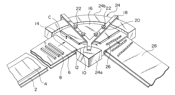
Fig.l shows a first embodiment of the present inventlon.
In this embodlment a dough sheet 4 is conveyed by a
first conveyor 2 and ls cut into bar shaped dough piece~
8 by a cutting device (not shown) and the dough pieces
are conveyed onto an lnlet conveyor 6. The dough pleces
8 are then transferred to a curved endless conveyor 10.
The curved endless conveyor 10, which ls ln the form of a
quadrant, ls contiguous to the downstream side of the
inlet conveyor 6.
A Ean-shaped plate 16 is mounted to a supporting member,
namely, arms 18, above the curved conveyor 10, so that
clearance C is present between the conveyor 10 and the
plate 16. The curved endless conve~or and the fan-shaped
plate constitiute a dough twisting station.
The clearance C, namely, the height of the fan-shaped
plate, can be ad~usted by height ad~usting means 2C
having handles 22, each consiRtlng of a knob and a bol
lnserted through the threaded through holes ln the a
18 into corresponding threaded holes ln the fan-shaIJ~d
plate 16. By turnlng the handIes 22, the plate 16 can be
ralsed or lowered.
A frame 24 having an lnner frame portion 24a and an
outer frame portion 2~b is provided. The frame 24
supports the arms 18 and the endless curved conveyor 10.
The structure, and its driving mechanism, of t.he cur~ed
endless conveyor 10 will now be explalned.
The curved endless conveyor 10 has a uniformly curved
-- 5
29~8787
run. Rollers are rotatably mounted vla shafts to the
frame 24 at the upstream and the downstream sldes of the
curved endless conveyor. Namely, one end of each of the
shaft~ ls journaled to the lnner portlon 24a of the frame
24, and each of the other ends of the shafts~ls ~ournaled
to the outer portion 24b of the frame. On these rollers
a curved endless conveyor belt is entralned. The belt ls
formed so as to conform to the curved endless conveyor
10. A sprocket ls flxed to each of the shafts adjacent
to the outer frame portion 24b, and a curved endless
chaln ls entralned around the sprockets so as to extend
and move along the curved outer perlphery of the conveyor
belt. A plurallty of sprlngs are used to connect the
outer perlphery of the conveyor belt to the curved
endless chain. The chaln moves along a curved path of
the outer perlphery of the curved conveyor gulded by
approprlate gulde means. A conveyor drlve motor ls
mounted to the frame 24 below the conveyor belt and a
drlve chaln ls entralned around the drive shaft of the
motor and one of the sprockets. As ls apparent, when the
motor ls drlven, the endless chain ls moved ~o advance
the outer perlphery of the conveyor belt a~ a speed
faster than that of the lnner perlphery. The above ls
only an example of the curved endless conveyor 10, and
there can be many varietles. For example, the upstream
and downstream rollers may be of such a form that the
dlameter constantly lncreases from the lnner end to the
outer end at a rate proportlonate to the length of the
run of the conveyor belt at lts outer perlphery over lt4
lnner perlphery.
In operatlon, the clearance C 15 flrst ad~usted so that
the height of the fan-shaped plate 16 ls made to be less
than the thlckness of the dough plece 8. The dough plece
carrled by the lnlet conveyor 6 ls recelved between the
curved endless conveyor 10 and the fan-shaped pla~e 16.
The dough plece thus recelved ln the clearance C wlll be
-- 6
2~8787
uniformly and completely twlsted ln lts entlrety whlle lt
moves through the the curved endless conveyor 10 and the
fan-shaped pla~e 16 due to the dlfference ln speed
between the radlal lnner perlphery 12 and the outer
radlal perlphery 14 of the curved endless conveyor.
For instance, lf a quadrant havlng a radlus of 15cm,
wlth its inner radial periphery at a distance of 5cm from
the center of the clrcle, ls used, the lnner radlal
periphery 12 advances about 8cm, the outer periphery 14
advances about 24cm, as apparent from the following
calculatlons.
Inner Periphery: (5+5)x3.14.4=7.85
Outer Periphery: (15+151x3.14 4=23.5
If flne rldges or undulatlons are provlded on the lower
surface of the fan-qhaped plate 16, the frlctlonal
resistance of the fan-shaped plate agalnst the dough
pleces wlll lncrease.
As was already mentloned, when, ln the arrangement
descrlbed above, the bar-shaped dough pleces 8 are
conveyed and passed through the clearance C, they are
entirely and uniformly twisted.
The twisted products 26 are then tranferred onto the
outlet conveyor 28.
The curved endless conveyor acts to change the conveylng
dlrectlon by an angle of about 90 degre-es, ln this flrst
embodiment.
Fig. 2 shows a second embodiment of thls lnvention.
In thls embodiment the bar-llke dough pleces 32 are
conveyed onto an lnlet conveyor 34 from a secondjconveyor
30. Instead of the curved conveyor 10 of the quadrant
-- 7
2~1 87~7
typ~ used ln the flrst embodiment, a semicircular curved
conveyor 36 ls used. The drlving mechanlsm of the curved
endless conveyor 35 ls substantlally the same as that of
the conveyor 10 of the first embodiment. Since the
angular extent of the conveyor 36 is about 180 degrees,
as opposed to 90 degrees in the f1rst embodlment, the
fan-shaped plate 38 in this case occupies part of the
conveyor. Of course a fan-shaped plate havlng the same
angular extent as that of the 180 degree conveyor 36 can
be used, if desired.
The dough pieces 32 are conveyed onto the curved
conveyor 36 radlally of the upper reach of the conveyor
and carrled toward the fan-shaped plate 38 wlthout belng
rolled. The dl~tance between the outer ends of the
ad~acent dough pleces becomes greater than that of the
ad~acent lnner ends thereof, due to the dlfference ln
speed between the outer perlphery and the lnner perlphery
of the curved conveyor, a~ was prevlously explalned.
The dough pleces then .enter the clearance between the
curved conveyor and the fan-shaped plate. The twisted
products 42 are dlscharged from the curved conveyor to
outlet conveyor 44. The reference numbers 40 show aI
mounted to the frame and supportlng the fan-shaped plate
38. The frame also supports the endless curved conveyor
36.
Flg. 3 shows a thlrd embodlment of the present
lnventlon.
As 1~ apparent from the drawlng, dlvided dough sheets 46,
48 are prepared to form two rows of bar-shaped dough plec
es 50, 52. Twlsted products are shown by number~ 54, 56.
Regarding the angular extent of the curved endless
conveyors, ln the flrst and thlrd embodlments
-- 8
2018787
quadrant-type curved conveyors are shown, while in the
second embodiment a semicircular curved conveyor is
shown.
However, the angular extent of the curved conveyor is
not limlted to only such types. Namely, the angular
extent can optionally be determlned withln the extent of
a semlclrcle of about 180 degrees, dependlng on the
layout of the factory, thus bringing about the advantage
of changlng the dough conveying dlrections without uslng
any addltlonal devlce.
As described above, according to the prior art dough
twlstlng machlne, dough pleces were contacted by two or
three endless belts, namely, one holding belt and one or
two twistlng belts. Thus the relatively long portions of
the dough pieces that are not contacted by the twisting
belts cannot be unlformly twlsted due to the plastlclty
of the dol~gh materlal. Further, the portlon of the dough
held between the holding belt and the conveyor cannot be
twlsted at all. These disadvantages derive from the
technical concept of using narrow belts to twlst plastlc
doughs.
In contrast to such a structure, accordlng to thls
lnventlon, dough pleces can be completely and uniformly
twl~ted by uslng a curved endless conveyor and a
fan-shaped plate posltloned above and spaced apart from
the cuxved endless conveyor. The dough pleceR are
conveyed lnto the clearance between the curved endless
conveyor and the fan-shaped plate and are unlformly
twlRted from end to end as they pass through the
clearance.
By uslng such a structure, the disadvantages of the
prlor art machlne have successfully been overcome.
In addltlon, by using the curved conveyor of a dlfferent
g
2~8787
arcuate dlstance, the dough conveying directlon can
easlly be changed depending on a factory's space
requlrements.
~;
-- 10 --