Note: Descriptions are shown in the official language in which they were submitted.
rlY~
~ 201880~ ~
MODULAR MISSILE UPGRADE APPARATUS
BACKGR OUND O F THE INVENT ION
Field of the Invention:
This invention relates generally to modular missiles and more
par ti cularl y to t ube-la unched op ti c ally-t racked wi re- gui ded
5missi les.
Description of Related Art:
These missi les were developed around two decades ago as
portable missiles to be used against ground based vehicles or
installations. These original missiles, and successors variations,
10 were designed in a modular fashion. As an example, the electronics
module is a separate unit and can be upgraded easily without
requiring modification to the remainder of the missile. Similarly,
all of the basic components of the missile are designed in modules
to pe rmi t e asy up grades as te chnolo gy adv ances .
15These missiles typically utilize a shaped charge warhead.
The s haped charge warhe ad con tains a coni cal shaped c opper liner
which collapses and melts during detonation and exploslon of the
warhead. The melted copper forms a plasma ~et that is directed out
~ 2018809
- 1 the f ront o f the warhead towards the target.
One disadvantage of these missiles is that the switch which
initiated detonation of the warhead was placed only a few inches
from the copper liner and did not permlt enough time for the plasma
Jet to be completely formed before the exploding warhead collided
with the target. Hence, the maximum effectiveness of the plasma
~et was not obtai ned.
One modular improvement made to these missile is the
replacement of the rudimentary nose module with an updated uarhead
with a probe module having an extensible probe to provide s tandof f
detonation. The probe extends upon launch ahead of the warhead and
contains a switch which activates the warhead detonation. The
extensible probe permits enough time for the plasma Jet to be
properly formed before collision betueen the warhead and the
target. This feature increases the armor-piercing capability of
the missile.
Subsequent missiles were developed with a heavier and more
powerful warheads and also with an extensible probe for increased
s tand of f de tonati on .
In response to these improvements in warhead efficiency,
reactive armor was developed. When reactive armor explodes, a
sheet of steel is forced upward through the plasma Jet. Although
the plasma Jet easily burns the steel, the reactive armor is placed
at an angle so that the rising sheet of steel presents an ever
fresh steel face which breaks up the plasma Jet, thereby destroying
the plasma Jet's effectiveness.
~ ~ 2018809 t
To counter the reactive armor development, a small charge uas
- placed behind the tip switch in the extensible probe. Detonatlon
of the warhead was delayed for a short period of time after
detonation of the tip charge in the extended probe. The small
charge activated the reactive armor, thereby clearing the uay for
the warhead's plasma ~et to defeat the unprotected armor on the
side of the tank or other such target.
SUMMARY OF THE INVENTION
The present invention recognizes the llmitations of existing
the tube-launched missiles relative to reactive armor. For these
missiles, the existing probe module without a tip charge is removed
and discarded. An adaptor connects the existing warhead to a probe
module containing an extensible probe with a tip charge. Suitable
wiring is accomplished through the use of a single cable. A faring
is added to create the proper aerodynamics for the enhanced
tube-launched missile of the present invention.
Within the preferred environment of the present invention,
modification of an modular tube-launched missile having a five inch
warhead, the steps taken are:
(1) The existing five inch probe module of the missile is
removed and discarded; ;
(2) The five-inch warhead module of the missile is removed
from the missile;
(3) The Safe and Arm ( S&A) of the warhead is disconnected
from the electronics module; a new cable is connected to the
4 2018809
wlres from the electronlcs motule ant the wlres to the S&A of
the flve lnch warhead;
(4) The warhead ls reattached to the mlsslle; the new cable
ls placed along the outslde of the warhead and threaded
through an orlfice ln the adapter;
(5) The farlng ls secured to the slx lnch neck of the
adaptor (creating the proper aerodyna~lcs for the ~isslle);
(6) An adaptor and farlng are attached to the five inch
warhead; the adaptor has another neck being six inches ln
dlameter; and,
(7) A slx lnch probe module wlth extensible probe with tip
charge ls wlred to the new cable prlor to the probe ~odule
belng attached to the slx lnch neck of the adaptor.
Other aspects of this invention are as follows:
A kit for the conversion of a missile to provide an
improved warhead module, said kit comprising:
(a) an adapter having a first neck and a second
neck, said first neck being attachable to said warhead
module;
(b) a probe module attachable to the second neck
of said adapter; and,
(c) a faring attachable to the second neck, said
faring extending past said warhead module.
A method of converting a missile having an
electronics module, a warhead module, and a probe
module, to be effective against reactive armor, said
method comprising the following steps of:
(a) removing the probe module of the missile from
the warhead;
.~
~'
2018809
4a
(b) disconnecting wires extending between the
probe module and the electronics module of the missile;
(c) placing a faring over the warhead;
(d) connecting a first side of an adaptor to said
warhead;
(e) connecting said faring to a second side of
said adaptor; and,
(f) connecting a probe module to a second side of
said adaptor.
BRIEF DES~IPTION OF THE DRAWINGS
Figure 1 is a cutaway view of sn embodiment of the invention
illustrating the lnterrelationship of the six inch probe module,
the adaptor, and the five lnch warhead.
Figure 2 is a side view of an embodiment of the adaptor.
Figure 3 is a cutaway view of an embodiment of the invention
illustrating the wire cable and it's function.
Figure 4a ls a cutaway side view of a typlcal tube-launched
modular missile's nose without an extenslble probe.
Flgure 4b ls a cutaway slde vlew of a tube-launched mlsslle
with the extenslble probe extended but lacklng a tlp charge.
~'-'t'
~`- 2018809
- 5
Figure 4c is a cutaway side view of a missile utilizing the
present invention to incorporate a probe module with extensible
probe with tip charge on an existing tube-launched missile.
Figure 5 is a side view a modified tube-launched missile in
f ligh t conf igurat ion.
DESCRIPTION OF THE PREFER~ED EMBODIMENTS
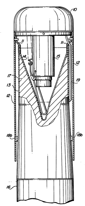
Figure 1 is a cutaway vieu of an embodiment of the invention,
mating a six-inch probe module to a five-inch uarhead module.
In this embodiment, the six inch probe module 10, shown in a
10 stoued condition, is attached to the six inch neck of adaptor 11.
The five inch neck of adaptor 11 attaches to the five inch warhead
13 of missi le 16.
~ larhead module 13 consists of an explosive charge 17 with a
coppe r line r 14 . The c ombina tion o f expl osive charge 17 an d copp er
liner 14 creates a shaped charge which forms the plasma ~et.
During explosion of explosive 17, the copper liner 14 collapses,
melts, and forms the plasma ~et which is used to penetrate the
armor of the target vehicle.
Faring 12 connects to the six inch neck of adaptor 11 and
20 extends past the uarhead module 13 to the portion of the
tube-launched missile 16 uhich is six inches in diameter. In this
manner, the aerodynamics of the missile is preserved even though it
. . .
nou has a six inch probe module.
Probe extension 15 is periscoped uithin the probe module 10
during shipment and is only extended at launch. Probe extension 15
~ 2018809
_ 6
easily stores within the cavity formed by copper llner 14. Since
probe extension 15 is extended at launch, and therefore at the
point of detonation, the cavity formed by the copper llner 14 is
left undisturbed during use of the enhanced missile.
Scuff pads 18a are attached to adapter 11 and are used to
center the missile at the forward end within its launch tube and
guide the missile during its launch from the tube.
Pads 18b support and center the farlng around the reduced
area of mis sile 16.
~ire cable 19 transfers power from the electronics unit (no t
shown) to the probe module 10.
Figure 2 illustrates the adaptor used in the embodiment first
described in figure 1. In this embodiment, adaptor 11 has three
basic sections: the five inch neck 20; the six inch neck 21; and
the expansion ~oint 22.
The length of the expansion ~oint 22, illustrated by d, is
chosen to make the enhanced missile have the same general overall
length as a regular tube-launched missile. This eliminates the
need for any modification to the accessory equipment such as
shipping boxes, launch tubes, etc.
Also located in the expansion ~oint 22 is orifice 23 which
permi ts the wire cable (not s hown) to pas s between the elec tronic s
unit (not shown) of the missile and the probe module.
,
Although this embodiment illustrates that the six inch collar
21 is ahead of the five inch collar 20, those of ordinary skill in
the art readily recognize that the distance, d, of the expansion
i~ 2018809
~oint 23 is ad~ustable to fit the requirements of the missile being
modified. It is totally possible that the expansion ~oint for some
missiles has the wider diameter neck actually placed behind the
smaller diameter neck. The adaptor for this situation would be
shaped like a "Z" and would be used to shorten the missile length.
The distance d of the expansion ~oint 23 also enhances the
missile by increasing the standoff distance between the target and
the warhead, thereby increasing the effectiveness of the plasma
J et ' s penet ration .
- Figure 3 illustrates the wiring concerns when the missile is
modified to become the enhanced missile of this invention. The
five inch warhead 13 has a three wire connection. In the
traditional missile arrangement, these three uires attach to three
wires from the Electronics Unit (EU ) module 32. The three wires
are used for the Safe and Arm (S&A) 33 operation.
For the modification of the typical tupe-launched mlsslle,
these three wires are disconnected and reconnec ted to three wires
at end 31b of wire cable 19. The four wires from the cable 30 at
end 3 lb, ar e connected to the S&A 3 3 .
Wlre cable 19 extends between faring 12 and the exterior of
warhead 13 entering through the ori fice 23 in adaptor 11.
Wire cable 19 supplies power from the electronics unl t 32 to
the controller 35. Thls power is supplied by connection of end 31a
.
to the cont roller 35 . Contro ller 3 5 acti vates the S&A 33 o f the
warhead module 13 via wire cable 19. Additionally, controller 35
activates the Saf e and Arm (S&A) 34 of the tip charge via wlre
i. 2018809
cable 36.
Operationally, a switch (see figure 4b) located at the end of
probe extension 1 5 is closed through the crushlng of the probe from
lmpact with the target. Thls causes the controller 35 to detonate
the tip charge (not shown) in probe extension 1 5 via wire cable
36. A selected delay is created before warhead 13 is detonated by
contr oller 35.
In this manner, of detonating the extended probe tip charge
and waiting a selected amount of time before detonating the
warhead, the enhanced missile not only nullifies the effectiveness
of reactive armor, but it also assures that the plasma ~et is fully
formed before the missile's warhead collides with the target.
Figure 4a illustrates the relatlonship of a traditional
tube-launched nose module 43 without an extensible tip, warhead 13,
and activation switch 44. The distance between the leading edge of
warhead 13 and the activation switch 44, contained within nose 43,
is indicated by "a". This distance does not establish enough of a
standoff to permi t the plasma ~et to be f ully f ormed.
Figure 4b illustrates the typical tube-launched missile probe
module with extensible probe but wi thout a tip charge .
In figure 4b, the missile has an extensible probe 45 with a
contact sensing switch 41 at the tip thereof. This increases the
standoff distance to "b" and permits an optimal plasma ~et to be
.
formed. However, the plasma Jet alone is ineff ective against
vehic les wi th rea ctive armor .
: 2018809
In the enhanced missile of the present invention, illustrated
in figure 4c, probe 15 i~s extended at launch. This extension of
probe 15 places the contact sensing switch 42 a distance, "c", from
the leading edge of warhead 1 3. This dis tance, c, provides more
than enough time for warhead 13 to properly create the desired
plasma ~et.
Additionally, probe 15 contains a tip charge (not shown) in
the vicinity of contact sensing switch 42 which is detonated upon
contact of probe 15 with the target. This detonation activates any
reactive armor on the target so that it is removed from the
missile's path permitting the plasma ~et of the missile to address
the now unprotected armor of the target.
Figure 5 illustrates the enhanced missile of the present
invention in flight configuration. After launch, probe extension
15 is extended past the front of probe module 10. Warhead 13, the
outline of which is noted by 52, is a standard five inch warhead
and i s cont ained wi thin f arin g 12.
The enhanced missile's activity is controlled by electronics
unit 51 and is well known in the art. Propulsion module 50
provides propulsion and the launch motor 54 provides launching of
the enhanced missile of this invention. Propulsion module 50 and
the l aunch motor 54 are well known in the art .
It is clear from the forgoing that the present invention
provides for an enhanced tube-launched modular missiie requiring
minimal modification.