Note: Descriptions are shown in the official language in which they were submitted.
-- 20 1 8883
BACKGROUND OF THE INVENTION
2 Field Of The Invention
3 This invention relates to ozone generators and methods. More
4 particularly, it concerns power supplies applicable to ozone generators,
especially those using tubular electrodes, and methods of generating ozone
6 therewith.
7 Discussion Of The PriorArt
8 Industrial ozone generators using tubular electrodes are usually
g composed of a set of elementary generators connected in parallel within the
0 same enclosure, each generator co~ isillg two conducting electrodes
11 separated by a narrow gap, through which a gas is passed, and a dielectric
12 material, usually glass. These electrodes are concentric. Inside an outer metal
13 electrode, around which cooling water circulates, a glass tube is placed. The
14 glass tube is closed at one end and metalized internally, such metalization
con~liluling the second electrode. A small discharge gap, e.g., 1-2 mm, is
16 provided between the glass tube and the metal tube through which is passed
17 either pure oxygen or a gaseous llli~lUle, such as atmospheric air containing
18 oxygen.
19 Between the two electrodes an increasing alternating potential
dirrerellce~ which is above a specified voltage corresponding to the breakdown
21 voltage of the gas, is applied across the terminals of the generator. There
22 appears in the discharge gap a violet corona resulting in the partial convelsion
23 of oxygen into ozone. Ozone forms when oxygen molecules are accelerated
24 and collide in an alternating electric field. This formation only occurs when
there is a voltage gradient and the electric field has reached the necessary
2 6 strength to ionize the gas.
27 Ozone production by such generators is an increasing function of the
28 electrical power applied thereto and the control of the production at the
29 required value is, therefore, effected by adjusting said power.
In the past, significant refinements have been made to ozone
31 generators and their integral power supplies. These refinements have been
32 directed at increasing the efficiency of the generator or the power supply.
33 It is known that an ozone generator can be powered by a supply
34 consisting of a saturable core reactor and an air gap transformer. This
20 1 88~3
method as disclosed in U.S. patent 4,587,591 operates at line frequency,50 or
2 60 hertz.
3 It is also known that the efficiency of an ozone generator can be
4 increased by increasing the power supply frequency above the commercial AC
line frequency. However, there is a lllaxilllulll practical level for the
6 frequency. In the past, these medium (50 to 1,000 hz) and high (above 1,000
7 hz) frequency power supplies have been voltage fed inverters. Since the power
8 to each of the tubes must be controlled and the start of the corona is voltage
g dependent, it was obvious to adjust the voltage of the electric field. These
power supplies have either had natural or forced comlllulation. The latter
11 method is taught in U.S. patents 4,680,694 and 4,713,220.
12 Industrial generators which are made up of multiple elementary
13 generators inherently have a large amount of stored energy which could feed
14 through to one elementary generator in the case of a short circuit (broken
dielectric tube). It is good engineering practice to fuse each dielectric tube to
16 protect against short circuits.
17 Since the voltage source inverter supplies a voltage w~vefolm to the
18 load, the current is uncontrolled and determined by the load. Under faulting
19 conditions of the load itself (ozone generator-broken dielectric tube), the
resulting electrical short of the load will cause the current as supplied by the21 power supply to rapidly increase to uncontrolled destructive levels. This will
22 result in a failure to comlllulate (turn-off) an inverter thyristor which then
23 results in an internal short circuit within the inverter itself. This short circuit
24 appears across the very large capacitor bank on the dc link which further
results in fault ~;ullen~s. Thus, under faulting conditions of the load, a short26 circuit can cause uncontrolled destructive levels of ~ ents to flow.27 In order to shut down a voltage source inverter power supply under
28 faulting conditions, the firing pulses to the inverter thyristors must stop. The
29 current left flowing in the devices is influenced by the fault ~;ulle~ described
above. In practice various types of protective schemes have been devised to
31 self protect the voltage source inverter power supply, but each has some
32 disadvantage. The result is that these schemes are only marginally successful
33 and involve power components which result in additional circuit losses that
34 result in lower efficiencies.
20 1 8883
The major disadvantage of the voltage source power supply is its
2 unreliability in not being able to control culle~ . This type of power supply
3 collvenlionally has been air-cooled which limits operating the thyristor to near
4 its full current rating. This method of cooling also opens the equipment
s cabinet to the ellvilonll-ent and increases maintenance costs. Such prior art
6 power supplies make use of several electromagnetic elements that have
7 considerable weight and occupy a great deal of space. They are also relatively
8 expensive.
g The present invention provides illlplovelllents in the structuring and
operation of ozone generators to mitigate or elimin~te the defects of prior
known devices as discussed above.
2 It is known that ozone generators can be powered by a cullelll source
13 inverter, compensation reactor and a high voltage transformer (see U.S.
14 patent 4,790,980). This present invention make it possible to elimin~te the
need for a separate compensation reactor.
16 OBJECTS
17 A principal object of the invention is the provision of more reliable
18 and more economical ozone generators.
19 Further objects include the provision of:
1. Impruv~d ozone generators that utilize a 1ullent fed inverter
21 power supply which includes an air-gap high voltage ll~ rolll.er providing the
2 2 necessary electrical characteristics for resonance with the load.
2 3 2. Such generators that, under faulting load conditions, prevent a
2 4 short circuit from causing uncontrolled destructive levels of currents to flow.
2 5 3. Illlproved ozone generation methods that are more reliable and2 6 economical than prior known methods.
2 7 Other objects and further scope of applicability of the present
2 8 invention will become apparent from the detailed descriptions given herein; it
2 9 should be understood, however, that the detailed descriptions, while indicating
~lefelled embodiments of the invention, are given by way of illustration only,
31 since various changes and modifications within the spirit and scope of the
3 2 invention will become apparent from such descriptions.
3 3 SUMMARY OF THE INVENTION
34 The objects are accomplished in accordance with the invention by
providing ozone generators with a current source power supply, whereby the
2~8883
power supply only supplies a controlled output ~;ullellt w~vefollll to the load.2 The voltage is uncontrolled and determined by the load. As a result, under
3 faulting conditions of the load, a short circuit cannot cause uncontrolled
4 destructive levels of ~;ullenls to flow.
An illlyrovt;d power supply of this invention comylises a controlled
6 AC/DC three-phase bridge rectifier coupled through two current filter
7 reactors to a DC/AC thyristor inverter. The inverter is then coupled to the
8 primary of an air gap high voltage ll~n~follller. The ozonator load is ag capacitive load, and of a low power factor and is electrically characterized as a
dielectric capacitance in series with the parallel combination of the air gap
capacitance and an avalanche diode whose breakdown voltage is the same as
12 the corona threshold voltage. The power supply operates at a frequency
13 dependent on the parallel resonant frequency of an air gap transformer in
14 parallel with the reflected load capacitance.
In the current fed inverter of the invention, the d.c. supply is of high
16 impedance because of the presence of d.c. filter reactors. Therefore, the
17 output current waveform is held con~lallt by this inductance while the output
18 voltage waveolm depends upon the nature of the load impedance. The
19 output w~vt;rollll and the power can be ,,,~xi.,,i~d through the use of a
natural resonant circuit. An air gap in the iron core of the high voltage
21 llansrollller supplies the necessary high impedance for resonance. Therefore,
22 the invention provides great illlyl~velllent in power supplies for ozone
23 generators and eliminates the need for a separate high impedance
2 4 electromagnetic element from the circuit as required in prior known devices.
In accordance with the invention, to shutdown the cullelll source
2 6 power supply under faulting conditions, all inverter thyristors are gated to an
27 "on" condition deliberately shorting the output terminals of the power supply
28 and placing a short on the dc link of the power supply. In this manner, the29 rate of rise of fault current is limited by the very large, current filter, inductive
reactance on the dc link. As such, the slow rate of rise of dc link current
31 merely needs monitoring of the "turn off" time and when out of range of
3 2 shutting down the ac-dc rectifier on the mains. In accordance with the
3 3 invention, power supply short circuit protection is accomplished by monilolillg
34 the w~vefollll turn-off time every half cycle and compalillg it against what is
required. If these do not agree the inverter Ill~lislols are fired full on and the
2~.8~l5 3
rectifier thylisLols are turned off. When the fault has cleared the circuit
2 resumes normal operation.
3 Providing the generator with a source of cooling water, and designing
4 all thyli~lor bridges and electromagnetics to be water-cooled has significantly
reduced the size and weight of protective cabinets, deleted the maintenance
6 cost of replacing or cleaning air filters, and reduced the size and cost of the
7 thyristors for a particular power requirement as compared to air-cooled8 thyristors.
g BRIEF DESCRIPTION OF THE DRAWINGS
A more complete understanding of the invention can be obtained by
11 reference to the accoll.pal.yillg drawings in which:
12 FIG. 1 is a schematic circuit diagram of a prior art device, for the
13 generation of ozone, which is supplied by a voltage source inverter.
14 FIG. 2 is a schematic circuit diagram of a device in accordance with the
invention, for the generation of ozone, which is supplied by a ~;ullelll source
16 inverter.
7 FIG. 3 co~llplises four schematic circuit diagrams for the explanation
18 of the four conditions of inverter operation in accordance with the invention.
20~8~83
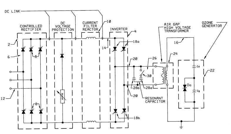
DESCRIPTION OF PREFERRED EMBODIMENTS
2 As shown in FIG. 2, the dc current source 2 for the inverter 4
3 complises a pulse, fully controlled, phase-controlled bridge rectifier 6
4 (converter), prefel~bly formed of thyristors, in this case silicon controlled
rectifiers (SCRs) 8, in conjunction with a large inductive filter reactor 10,
6 which collvell~ the input ac voltage of three phase line 12 to controllable
7 direct current. The magnitude of the constant dc curlelll supplied to the
8 inverter 4 can be conLilluously controlled through phase delay of the firing
g pulses supplied to the rectifier SCR's 8.
The purpose of the controllable dc current source 2 is twofold. First, it
11 provides a means for continuously controlling the inverter output high
12 frequency voltage and power. Secondly, it provides a rapid means for
13 controlling and limiting the input current to the inverter (and hence also the
14 cullelll drawn from the three phase lines). On switching off the system, the ac
bridge rectifier 6 thyristor gate control signals are reversed so that the energy
6 stored in the rectifier current filter reactor is fed back to the ac three phase
17 line 12. Thus, a very rapid means of protection is provided against overload
18 and fault conditions.
19 If an inverter or load short circuit fault should arise, the large dc filter
reactor 10 so limits the rate of rise of the direct ~;ullenl that sufficient time is
21 available for the over current trip to switch off the power supply long before
22 an unacceptable high level of fault ;ullelll is achieved. The magnitude of the
23 conslant ;ullellt that flows, on the dc link 14, through the large inductive
24 reactance 10 establishes the power supplied to the inverter 4.
The inverter changes the dc ~;ullellt to alternating square wave current
26 to the load circuit 16 which altogether forms a parallel resonant circuit. The
27 thyristors 18a & 18b used in the inverter 4 are specially selected to have a fast
28 turn-on time and high di/dt characteristics, fast turn-off time and high dv/dt
29 recovery characteristics. These requirements are necessary to enable the
thyristors to switch at frequencies used.
31 The dc-ac inverter 4 COllSi~lS of a fully controlled single phase bridge.
32 By gating the SCR's 18 of the bridge diagonals in turn, constant current of
33 alternate polarity is supplied to the load circuit 16, which is composed of the
34 air gap high voltage transformer 24 and the ozone generator 22 that form a
parallel resonant circuit. Hence, the inverter is a constant current source. The
2018883
frequency is determined by the load voltage buildup on a parallel resonant
2 circuit. Thus, the dc-ac inverter is carried on load and the frequency of
3 operation will merely follow and track the natural parallel resonant circuit
4 frequency. In this manner the output power factor for a given operating
condition is at all times at a lll~illlUlll value.
6 The basic principle of the current source type inverter is explained by
7 lererellce to the circuit shown in FIG. 2, a constant and essentially smooth
8 cullelll is supplied to the inverter 4 from dc source 2 through the dc filter
g reactor 10. This constant direct current is switched in opposite directions
through the output circuit by alternating firing SCR pairs 18a and 18b. The
resulting output current has an essentially square waverollll and each SCR
12 conducts for a period corresponding to half the total output cycle time. This
13 output voltage at the inverter terminals 20 assumes whatever waveshape is
14 a~lOpliate in response to the rectangular current waveform supplied to the
load.
16 Without an applied load, the inverter 4 itself does not supply any
17 output voltage. It only supplies the output current. Two basic conditions of the
18 output load circuit must be satisfied. First, the phase angle of the load at the
19 fundamental output frequency must appear leading by an amount sufficient to
ensure successful collllllu~ation of the current from one pair of SCR's to the
21 other. Secondly, the impedance of the output circuit to the higher order
22 harmonics of the rectangular current waverollll must be relatively low.
23 For the ozone generator 22, the load is capacitive, of a low power
24 factor and requires higher voltages than an inverter 4 by itself can supply. In
this case, the high voltage transformer 24 is manufactured with an air gap in
2 6 the iron core to correct the load's power factor to near unity without the need
27 of an additional inductor for resonance. This will then ",~xi",i~e the28 reactance loading of the power supply. Finally, since it is desirable for the
29 high voltage output w~verolm to be near sinusoidal in the presence of a
square wave of current from the inverter section, the Q factor of the ~C
31 tuned circuit 26 must be sufficiently high to filter out the higher order
32 harmonics of the cullent square wavefollll supplied by the inverter 4.33 Therefore, additional capacitance in the form of capacitors 28a and 28b are
34 added to the tuned LrC circuit to provide for the necessary Q factor. The
capacitor 28a is connected to the taps of switch 30 to allow for llillllll;l-g the
20 1 ~883
resonant frequency based on the actual amount of capacitance of the ozone
2 generator 22. This capacitance can change based on the amount of dielectric
3 tubes removed from service due to blown fuses. This trim is only necessary to
4 the extent that the operating frequency be held relatively constant.It is necessary only for the combined values of the capacitors 28a and
6 28b to be such as to "overcompensate" the inductive reactance of the air gap
7 high voltage tl~n~rollller 24 at the operating frequency and thereby present an
8 overall leading power factor to the inverter.
g During normal bridge operation, four conditions are to be considered.
During condition 1 (FIG. 3,A) the SCR's 1 and 3 are carrying the constant dc
11 link ~;ullen~, Idc, to the load. During condition 2 (FIG. 3,B), which is the
2 collll~lulation phase for SCR's 1 and 3, SCR's 2 and 4 are fired while the
13 resonant circuit capacitance of ozone generator 22 has the polarity as shown.
14 A rapidly rising coll~lllulation current Ik/2 is generated by the voltage
on the resonant circuit capacitance. The rise time of this colllll~ulation current
16 is only limited by the circuit inductance of the air gap high voltage transformer
17 24. This co,llll,u~ation current Ik/2 is of opposite direction to the ~;ullent flow
18 IDC in SCR's 1 and 3 which are extinguished and the dc link cu~lenl, Idc,
19 therefore changes over from SCR's 1 and 3 to SCR's 2 and 4.
Since the inductance of the dc link current filter reactor LD is very
21 large, during the col,ll"ulation interval, the dc link current cannot change
2 2 magnitude and is therefore constant. The co~ ulation phase must be
2 3 completed in time before the resonant circuit capacitance voltage has reduced
24 to zero and switched voltage polarity. The time interval from the completion
of the coll~ ulation phase until the resonant circuit capacitance voltage has
2 6 reduced to zero must be equal to or greater than the ~llinimulll turn off time
2 7 requirements of the inverter SCR's.
2 8 After the commutation phase of condition 2 is complete, SCR's 2 and 4
29 are carrying the con~lal~t dc link ;ulrel~t, IDC, to the load as shown in
condition 3 (FIG. 3,C). The direction of cullellt is opposite to that of
31 condition 1. During condition 4 (FIG. 3,D), the dc link current IDC is
3 2 collllllulated from SCR's 2 and 4 to SCR's 1 and 3.
33 The process is as described for condition 2. Therefore the cycle is
34 complete and operation during condition 1 is again obtained. As the SCR'S
are fired before each voltage zero, the rectangular current waveform is
201 8883
leading the near sinusoidal voltage wavefollll on the output of the inverter.
2 This gives a leading power factor to the medium frequency circuit which
3 means that the inverter is running at a slightly higher frequency than the
4 natural resonant frequency of the tank circuit. As the resonant frequency of
the tank circuit changes due to changes in the load conditions, the inverter will
6 adjust its frequency to maintain the correct turn off time.
7 The firing pulses for the inverter SCR'S are fed from the electronic
8 controls to gating circuits mounted adjacent to the SCR'S. The basis for the
g protection against overload and faults of the ozone generator is as follows.
The control for the inverter monitors the circuit reverse voltage
11 available for the "turn off time" of the SCR'S. This turn off time is provided by
12 the resonant load on the inverter operating with a leading power factor. That
13 is, the inverter switches polarity of or reverses the output current before the
14 load voltage reverses polarity. During operation, the circuit available turn off
time is monitored for each inverter thyristor. If any interval of turn off time is
16 less than specified, all inverter SCR'S are immediately "gated on", placing a
17 short at the output of the large dc link reactor. This short creates a slow rate
18 of rise of the dc link current which the control for the ac to dc rectifier senses
19 and shuts down the system.
Gating all inverter SCR'S on during faulting conditions is the safest
21 condition for the SCR'S to be in. The SCR'S are "on", hence they cannot be
2 2 overvoltaged. While they are "on" and the current through them limited and
2 3 controlled by the large current filter reactor 10 on the dc bus, they cannot be
2 4 subjected to over current values.
2 5 In constructing equipment in accordance with the invention and
26 carrying out its novel methods for the generation of ozone, one may use
27 commercially available rectifiers and current source inverters as described
28 along with basic designs in such publications as the 6th edition of the SCR
29 MANUAL by General Electric. The present invention with such a current
3 o source inverter utilizes a technique of generator power factor correction with
31 an air gap high voltage transformer to increase reliability and economy of
3 2 operation in ozone generation.
3 3 By way of example of a specific embodiment of the invention, the total
34 capacitance for a small industrial ozone generator 22 would be 0.434 micro
farads. The maximum inverter output voltage (Vp) is 800 volts and the
201 8883
generator ma~ ulll voltage (Vs) is 10,000 volts. The turns ratio of the high
2 voltage ll ~nsr(~ er 24 would be 0.08 through the use of the transformer turns3 ratio equation a = Vp/Vs. In order to calculate the reactance necessary to
4 correct the ozone generator's power factor, the generator capacitance will be
5 referred to the primary side of the air gap high voltage transformer 24. The
6 required transformer impedance is calculated using the transformer
7 impedance referral equation Zp = a2Zs, where Zp is the transformer primary
8 impedance, "a" is the transformer turns ratio and "Zs" is the transfolll-er
g secondary impedance. The equation for the impedance of a capacitive circuit
is Z = 0.1592/fC, where "f" is the frequency measured in hertz and "C" is the
11 capacitance measured in micro farads. By combining these two equations,
12 setting "f" at 600 and solving for the capacitance as referred to the primary of
13 the transformer, the capacitance is calculated to be 68 micro farads.
14 Although a range of frequencies is possible, it is advantageous to
15 achieve a frequency of 600 hz at l~ lum current.
16 Using the standard resonance equation f = 0.1592/(LC)- 5,
17 wherein "L" is the inductance measured in micro henries, "f" & "C" are as
18 stated above and taking into consideration manufacturing limitations, one can19 fabricate a transformer which has a 950 micro henries air gap inductance for
use in the stated ozone generator.
21 To achieve a frequency of 600 hz at m~xil.. u.. ~ ~;u--ent, the power
22 supply is tuned to a frequency of 580 hz using the resonant capacitor 28. Such
23 capacitor permits an increase in the Q factor of the output circuit and thereby
24 provides a near sinusoidal w~vefolm current to be passed to the ozone
2 5 generator 22. The resonant capacitor 28 is sized using the resonance equation
2 6 to be 11.5 micro farads.
27 The protective control arrangements of the invention provide for
2 8 automatic system restart after a fault has occurred by reapplying the SCR gate
29 control signals after a short delay has occurred. In this manner, as an
individual dielectric tube in the ozone generator becomes damaged, the
31 resulting short circuit arc over will cause a rise in current sensed by the SCR
32 "turn off time" monitor circuit as a lllinimulll or zero turn off time interval
33 shutting down the system by turning "on" all inverter SCR'S as described.