Language selection

Search

Patent 2019143 Summary

Third-party information liability

Some of the information on this Web page has been provided by external sources. The Government of Canada is not responsible for the accuracy, reliability or currency of the information supplied by external sources. Users wishing to rely upon this information should consult directly with the source of the information. Content provided by external sources is not subject to official languages, privacy and accessibility requirements.

Claims and Abstract availability

Any discrepancies in the text and image of the Claims and Abstract are due to differing posting times. Text of the Claims and Abstract are posted:

  • At the time the application is open to public inspection;
  • At the time of issue of the patent (grant).
(12) Patent Application: (11) CA 2019143
(54) English Title: COMPRESSION LOAD CELL FOR FARM FEED MIXER SCALE
(54) French Title: DYNAMOMETRE DE COMPRESSION POUR LES BALANCES MELANGEUSES DE MOULEES AGRICOLES
Status: Deemed Abandoned and Beyond the Period of Reinstatement - Pending Response to Notice of Disregarded Communication
Bibliographic Data
Abstracts

English Abstract


ABSTRACT
In a load cell for incorporation into an electronic weigh scale in turnincorporated into a portable or stationary machine for mixing feed for
livestock, it is common to incorporate said electric load cells into
said feed mixer in such a way as to result in said load cells being
loaded in compression while supporting said feed mixer. Said load
cells are generally used in combination with suitable display apparatus
to provide indication of the weight of the feed in said feed mixer. In
this invention, the load cell consists of a load sensing element in the
form of a vertically-oriented cylindrical body comprising a central
sensing beam and two load introducing members immediately above and
below the sensing beam and connected to alternate ends of the sensing
beam in such a way as to allow a compressive load to be applied to said
load introducing members. The sensing beam incorporates a plurality of
electric resistance strain gages which sense shear strain in the beam
which is proportional to the applied load. Such strain gages are
connected in a bridge configuration to develop an electric signal which
is proportional to the applied load but relatively insensitive to
forces applied in any way other than compression between said load
introducing members. The electric signal may be transmitted to a
suitable electronic indicating device.


Claims

Note: Claims are shown in the official language in which they were submitted.

The embodiments of the invention in which an exclusive property orprivilege is claimed are defined as follows:
1. A load cell for measuring weight in a mixing machine comprising: a
vertically oriented cylindrical body adapted to include a central load
measuring beam with two load-introducing members, one located
immediately above and the other immediately below the said load
measuring beam, and connected to alternate ends of the load measuring
beam; a plurality of electric resistance strain gages fastened to the
said load measuring beam and connected in a bridge configuration in
such a way as to sense only load-dependent shear strain in the load
measuring beam and to provide an electric signal proportional to the
applied load.
2. A load cell as defined in claim 1 comprising a vertically oriented
square or rectangular body.
3. A load cell as defined in claim 1 or claim 2, but with one or more
additional load-isolation flexures attached directly above or below or
above and below one or more of said load introducing members.
4. A load cell as defined in claim 1 or claim 2 or claim 3, but with
one or more additional load isolation flexures attached immediately
adjacent to or beside one or more of said load introducing members.
-2-

Description

Note: Descriptions are shown in the official language in which they were submitted.


2 ~
SPECIFICATION
This invention relates to a load cell which measures applied weight in
a farm feed mixer and provides an electric signal which is proportional
to the applied weight which may displayed using a suitable indicating
device.
It is common in devices for measuring weight of ingredients being mixed
in feed mi~ing machines to incorporate a load cell comprising a column~
type load sensing element to which electric resistance strain gages are
fastened and connected in an electric bridge configuration in such a
way that the strain gages respond only to the compressive strains which
are created in said column element and which are proportional to the
amount of load or weight applied to sald column element, and to provide
an electric output signal which may be displayed on a suitable
indicating device. It is normal in column-type load cells to create an
error in the electric measurement slgnal due to misalignments in the
application of the load caused by changes in the load application
point, or angular loads or side loads or torsion loads. Such loading
errors result in an incorrect weight being displayed in the indicating
device, and this is particularly noticeable when incorporated into feed
mixing apparatus because of the vibration associated with the
mechanical operation of the mixer and the fact that it is common for
portable feed mixers to be subjected to travel over rough terrain. It
is also widely accepted that without special forms of compensation the
electric signal in a column-type load cell is inherently non-linear in
relation to the applied load, because of the strain-induced change in
cross sectional area and because of the unequal changes of resistance
within the strain gage bridge. Further, is often difficult to machine
a column element thin enough to provide a cross-sectional area small
enough to provide a strain level which is high enough to result in a
substantial electric signal. It is therefore unsatisfactory to use
coluMn-type load cells in this application because they exhibit a high
sensitivity to the loading errors which are common in this application,
because of inherent non-1inearity, and because of the relatively high
cost of machining thin column elements.
I have found that the disadvantages of the column-type load cell may be
overcome by a load cell utilising a beam-type sensing element, in which
shear strain is developed in a beam rather than compressive strain in a
column, but which may still be loaded in the same manner as the
previously described column load cell. The developed shear strains are
generally higher for a given cross-section than compressive strains,
because the modulus of elasticity in shear is approximately one third
of that in compress-ion. It is easier to manufacture for a given
capacity rating because the web may be of a workable dimension. Also,
-the shear strain occurring in the web of the sensing beam for a given
load is the same regardless of the point of load application. An
additional beneFit is that in the intended embodiment, adverse forces
acting upon the load cell are resisted to a much greater degree in a
beam desiyn t'nan in compression designs. Also, the relationship
between shear strain and applied load is much more linear than other
methods.
. ~_
:i,

2~.91 43
::
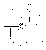
~: In drawings which illustra7te the current embodiment of the inven~tion,
: Figure 1 is a front elevation of the current embodiment,
Figure 2 is a rear elevation of the current embodiment,
Figure 3 is a side elevation of the current embodimént,
Fiyure 4 is a section of the line A-A of figure 1,
:Y Figure 5 is a top view of the current embodiment,
Figure 6 is a diagram of the bridge circuit connect,rlg the ~train
: gayes.
: The load cell illustrated: oomprises a vertical cylindrical solid body 1
: into whioh slots 2 or simllar detail have been cut into opposite sides
: at separate points along the length of the said body, forminy a central
beam 3 and two~:load irltroducing members 4. If desired a pocket may
also be cut i~ito:the beam 3 :in such a way as to provide a thin wab 5.
Strain gages 5:are:then bonded to the side of the beam 3 or if a web is
provided to the side of tha web 5, such strain gayes connect6d
: electrically togetherl to form a bridge circuit 7 which may be excited
with an electric-: current to provide an electrical siynal output
proportional to the comprassive load or force applied to the load
introducing members 2.
, ~
'.,~
;
.
~:~
;~
~ :~
~:
::
:
'~:

Representative Drawing
A single figure which represents the drawing illustrating the invention.
Administrative Status

2024-08-01:As part of the Next Generation Patents (NGP) transition, the Canadian Patents Database (CPD) now contains a more detailed Event History, which replicates the Event Log of our new back-office solution.

Please note that "Inactive:" events refers to events no longer in use in our new back-office solution.

For a clearer understanding of the status of the application/patent presented on this page, the site Disclaimer , as well as the definitions for Patent , Event History , Maintenance Fee  and Payment History  should be consulted.

Event History

Description Date
Inactive: Inventor deleted 2001-01-18
Time Limit for Reversal Expired 1992-12-18
Application Not Reinstated by Deadline 1992-12-18
Deemed Abandoned - Failure to Respond to Maintenance Fee Notice 1992-06-18
Inactive: Adhoc Request Documented 1992-06-18
Application Published (Open to Public Inspection) 1991-12-18

Abandonment History

Abandonment Date Reason Reinstatement Date
1992-06-18
Owners on Record

Note: Records showing the ownership history in alphabetical order.

Current Owners on Record
PAUL A. MCKENNA
Past Owners on Record
None
Past Owners that do not appear in the "Owners on Record" listing will appear in other documentation within the application.
Documents

To view selected files, please enter reCAPTCHA code :


To view images, click a link in the Document Description column. To download the documents, select one or more checkboxes in the first column and then click the "Download Selected in PDF format (Zip Archive)" or the "Download Selected as Single PDF" button.

List of published and non-published patent-specific documents on the CPD .

If you have any difficulty accessing content, you can call the Client Service Centre at 1-866-997-1936 or send them an e-mail at CIPO Client Service Centre.


Document
Description 
Date
(yyyy-mm-dd) 
Number of pages   Size of Image (KB) 
Abstract 1991-12-18 1 82
Cover Page 1991-12-18 1 39
Claims 1991-12-18 1 108
Drawings 1991-12-18 1 70
Descriptions 1991-12-18 2 159
Representative drawing 1999-07-15 1 4