Sélection de la langue

Search

Sommaire du brevet 2019143 

Énoncé de désistement de responsabilité concernant l'information provenant de tiers

Une partie des informations de ce site Web a été fournie par des sources externes. Le gouvernement du Canada n'assume aucune responsabilité concernant la précision, l'actualité ou la fiabilité des informations fournies par les sources externes. Les utilisateurs qui désirent employer cette information devraient consulter directement la source des informations. Le contenu fourni par les sources externes n'est pas assujetti aux exigences sur les langues officielles, la protection des renseignements personnels et l'accessibilité.

Disponibilité de l'Abrégé et des Revendications

L'apparition de différences dans le texte et l'image des Revendications et de l'Abrégé dépend du moment auquel le document est publié. Les textes des Revendications et de l'Abrégé sont affichés :

  • lorsque la demande peut être examinée par le public;
  • lorsque le brevet est émis (délivrance).
(12) Demande de brevet: (11) CA 2019143
(54) Titre français: DYNAMOMETRE DE COMPRESSION POUR LES BALANCES MELANGEUSES DE MOULEES AGRICOLES
(54) Titre anglais: COMPRESSION LOAD CELL FOR FARM FEED MIXER SCALE
Statut: Réputée abandonnée et au-delà du délai pour le rétablissement - en attente de la réponse à l’avis de communication rejetée
Données bibliographiques
Abrégés

Abrégé anglais


ABSTRACT
In a load cell for incorporation into an electronic weigh scale in turnincorporated into a portable or stationary machine for mixing feed for
livestock, it is common to incorporate said electric load cells into
said feed mixer in such a way as to result in said load cells being
loaded in compression while supporting said feed mixer. Said load
cells are generally used in combination with suitable display apparatus
to provide indication of the weight of the feed in said feed mixer. In
this invention, the load cell consists of a load sensing element in the
form of a vertically-oriented cylindrical body comprising a central
sensing beam and two load introducing members immediately above and
below the sensing beam and connected to alternate ends of the sensing
beam in such a way as to allow a compressive load to be applied to said
load introducing members. The sensing beam incorporates a plurality of
electric resistance strain gages which sense shear strain in the beam
which is proportional to the applied load. Such strain gages are
connected in a bridge configuration to develop an electric signal which
is proportional to the applied load but relatively insensitive to
forces applied in any way other than compression between said load
introducing members. The electric signal may be transmitted to a
suitable electronic indicating device.

Revendications

Note : Les revendications sont présentées dans la langue officielle dans laquelle elles ont été soumises.


The embodiments of the invention in which an exclusive property orprivilege is claimed are defined as follows:
1. A load cell for measuring weight in a mixing machine comprising: a
vertically oriented cylindrical body adapted to include a central load
measuring beam with two load-introducing members, one located
immediately above and the other immediately below the said load
measuring beam, and connected to alternate ends of the load measuring
beam; a plurality of electric resistance strain gages fastened to the
said load measuring beam and connected in a bridge configuration in
such a way as to sense only load-dependent shear strain in the load
measuring beam and to provide an electric signal proportional to the
applied load.
2. A load cell as defined in claim 1 comprising a vertically oriented
square or rectangular body.
3. A load cell as defined in claim 1 or claim 2, but with one or more
additional load-isolation flexures attached directly above or below or
above and below one or more of said load introducing members.
4. A load cell as defined in claim 1 or claim 2 or claim 3, but with
one or more additional load isolation flexures attached immediately
adjacent to or beside one or more of said load introducing members.
-2-

Description

Note : Les descriptions sont présentées dans la langue officielle dans laquelle elles ont été soumises.

2 ~
SPECIFICATION
This invention relates to a load cell which measures applied weight in
a farm feed mixer and provides an electric signal which is proportional
to the applied weight which may displayed using a suitable indicating
device.
It is common in devices for measuring weight of ingredients being mixed
in feed mi~ing machines to incorporate a load cell comprising a column~
type load sensing element to which electric resistance strain gages are
fastened and connected in an electric bridge configuration in such a
way that the strain gages respond only to the compressive strains which
are created in said column element and which are proportional to the
amount of load or weight applied to sald column element, and to provide
an electric output signal which may be displayed on a suitable
indicating device. It is normal in column-type load cells to create an
error in the electric measurement slgnal due to misalignments in the
application of the load caused by changes in the load application
point, or angular loads or side loads or torsion loads. Such loading
errors result in an incorrect weight being displayed in the indicating
device, and this is particularly noticeable when incorporated into feed
mixing apparatus because of the vibration associated with the
mechanical operation of the mixer and the fact that it is common for
portable feed mixers to be subjected to travel over rough terrain. It
is also widely accepted that without special forms of compensation the
electric signal in a column-type load cell is inherently non-linear in
relation to the applied load, because of the strain-induced change in
cross sectional area and because of the unequal changes of resistance
within the strain gage bridge. Further, is often difficult to machine
a column element thin enough to provide a cross-sectional area small
enough to provide a strain level which is high enough to result in a
substantial electric signal. It is therefore unsatisfactory to use
coluMn-type load cells in this application because they exhibit a high
sensitivity to the loading errors which are common in this application,
because of inherent non-1inearity, and because of the relatively high
cost of machining thin column elements.
I have found that the disadvantages of the column-type load cell may be
overcome by a load cell utilising a beam-type sensing element, in which
shear strain is developed in a beam rather than compressive strain in a
column, but which may still be loaded in the same manner as the
previously described column load cell. The developed shear strains are
generally higher for a given cross-section than compressive strains,
because the modulus of elasticity in shear is approximately one third
of that in compress-ion. It is easier to manufacture for a given
capacity rating because the web may be of a workable dimension. Also,
-the shear strain occurring in the web of the sensing beam for a given
load is the same regardless of the point of load application. An
additional beneFit is that in the intended embodiment, adverse forces
acting upon the load cell are resisted to a much greater degree in a
beam desiyn t'nan in compression designs. Also, the relationship
between shear strain and applied load is much more linear than other
methods.
. ~_
:i,

2~.91 43
::
~: In drawings which illustra7te the current embodiment of the inven~tion,
: Figure 1 is a front elevation of the current embodiment,
Figure 2 is a rear elevation of the current embodiment,
Figure 3 is a side elevation of the current embodimént,
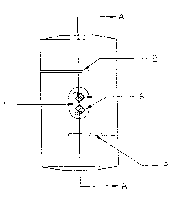
Fiyure 4 is a section of the line A-A of figure 1,
:Y Figure 5 is a top view of the current embodiment,
Figure 6 is a diagram of the bridge circuit connect,rlg the ~train
: gayes.
: The load cell illustrated: oomprises a vertical cylindrical solid body 1
: into whioh slots 2 or simllar detail have been cut into opposite sides
: at separate points along the length of the said body, forminy a central
beam 3 and two~:load irltroducing members 4. If desired a pocket may
also be cut i~ito:the beam 3 :in such a way as to provide a thin wab 5.
Strain gages 5:are:then bonded to the side of the beam 3 or if a web is
provided to the side of tha web 5, such strain gayes connect6d
: electrically togetherl to form a bridge circuit 7 which may be excited
with an electric-: current to provide an electrical siynal output
proportional to the comprassive load or force applied to the load
introducing members 2.
, ~
'.,~
;
.
~:~
;~
~ :~
~:
::
:
'~:

Dessin représentatif
Une figure unique qui représente un dessin illustrant l'invention.
États administratifs

2024-08-01 : Dans le cadre de la transition vers les Brevets de nouvelle génération (BNG), la base de données sur les brevets canadiens (BDBC) contient désormais un Historique d'événement plus détaillé, qui reproduit le Journal des événements de notre nouvelle solution interne.

Veuillez noter que les événements débutant par « Inactive : » se réfèrent à des événements qui ne sont plus utilisés dans notre nouvelle solution interne.

Pour une meilleure compréhension de l'état de la demande ou brevet qui figure sur cette page, la rubrique Mise en garde , et les descriptions de Brevet , Historique d'événement , Taxes périodiques et Historique des paiements devraient être consultées.

Historique d'événement

Description Date
Inactive : Inventeur supprimé 2001-01-18
Le délai pour l'annulation est expiré 1992-12-18
Demande non rétablie avant l'échéance 1992-12-18
Réputée abandonnée - omission de répondre à un avis sur les taxes pour le maintien en état 1992-06-18
Inactive : Demande ad hoc documentée 1992-06-18
Demande publiée (accessible au public) 1991-12-18

Historique d'abandonnement

Date d'abandonnement Raison Date de rétablissement
1992-06-18
Titulaires au dossier

Les titulaires actuels et antérieures au dossier sont affichés en ordre alphabétique.

Titulaires actuels au dossier
PAUL A. MCKENNA
Titulaires antérieures au dossier
S.O.
Les propriétaires antérieurs qui ne figurent pas dans la liste des « Propriétaires au dossier » apparaîtront dans d'autres documents au dossier.
Documents

Pour visionner les fichiers sélectionnés, entrer le code reCAPTCHA :


Pour visualiser une image, cliquer sur un lien dans la colonne description du document. Pour télécharger l'image (les images), cliquer l'une ou plusieurs cases à cocher dans la première colonne et ensuite cliquer sur le bouton "Télécharger sélection en format PDF (archive Zip)" ou le bouton "Télécharger sélection (en un fichier PDF fusionné)".

Liste des documents de brevet publiés et non publiés sur la BDBC .

Si vous avez des difficultés à accéder au contenu, veuillez communiquer avec le Centre de services à la clientèle au 1-866-997-1936, ou envoyer un courriel au Centre de service à la clientèle de l'OPIC.


Description du
Document 
Date
(aaaa-mm-jj) 
Nombre de pages   Taille de l'image (Ko) 
Abrégé 1991-12-18 1 82
Page couverture 1991-12-18 1 39
Revendications 1991-12-18 1 108
Dessins 1991-12-18 1 70
Description 1991-12-18 2 159
Dessin représentatif 1999-07-15 1 4