Note: Descriptions are shown in the official language in which they were submitted.
8~,~
~0-203
BACKGROU~D O~ THE IN~ENTION
This invention relates to thermoplastic containers
for the retention of fluids under pressure, such as
carbonated beverages and the like. These containers may
be prepared from a preform or parison which may be
injection molded, followed by blow molding said parison
into a suitably s~laped container. A typical
thermoplastic material is poly (ethylene terephthalate)
or PET, although others can be used.
The container configuration generally includes a
neck portion with a cap-receiving means, a shoulder
portion depending therefrom, a side wall or main body
portion depending from the shoulder portion and a bottom
wall joined to the side wall. In many of these
containers the bottom wall has a champagne bottle bottom
configuration with an internal, axially inwardly
directed, generally conical part.
The bottom wall of these containers represents a
weak part of the container. It is desirable to provide
a bottom shape capable of serving as a stable bottom
support.
Thus, beverage under pressure within the container
has a tendency to deform the bottom wall, as for example
everting the inwardly directed conical part to render
the bottom wall unstable.
98~
9~-203
Many attempts have been made to overcome these
problems while at the same time providing a construction
which is inexpensive and economical to process. For
example, U.S. Patent Number 3,881,621 provides a ribbed
strengthening at the bottom wall; however, this still
provides insufficient strengthening. U.S. Patent Number
4,134,510 provides a plurality of concentric annular
strengthening ribs and a plurality of additional
intersecting radial ribs in a complex and expensive
procedure. U.S. Patents 4,620,639, 4,261,948,
4,603,831, and 4,334,627 utilize a plurality of inwardly
projecting rigid ribs so that the bottom wall is thicker
at the ribbed portion than the remainder of the bottom
wall; however, this results in a container having
substantial and sharply defined differences in wall
thickness with resultant sharp temperature differences
in processing presenting difficult processing control
problems. U.S. Patent 4,865,206 utilizes a plurality of
wall portions extending downwardly from the bottom wall
forming hollow legs extending below the bottom wall
having planar feet whic~ are inclinea upwardly and
inwardly from the outer edges of the feet. ~ile mos-t
of the above improve the resistance to eversion, they
are limited to configurations resulting in insufficient
stability and insufficient compressive strength of the
bottle.
--3--
X ~ Lt
90-203
U.S. Patent 4,785,948, By Herbert Strassheimer,
teaches the use of an improved plastic preform for
forming blow molded plastic containers and resultant
improved plastic containers w~erein the container has a
tubular body portion adjacent a bottom portion and
extending onto the bottom portion having
circumferentially spaced radially extending continuous
alterations in wall thickness. The preform is
characterized by the bottom structure thereof having a
plurality of faces capable of forming a blow molded
plastic bottle with a bottom portion having said
circumferentially spaced radially extending continuous
alterations in wall thickness with a regularly
undulating cross section across the circumference
thereof, wherein said alterations in wall thickness are
progressive and gradual. While the teaching of U.S.
Patent No. 4,785,948 provides a stable and reinforced
bottom wall configuration which is simple in
construction and inexpensive to prepare and a preform
which is similarly convenient and expeditious to
prepare, such improvements are at times insufficient in
the case of large bottles. Thus, it is desirable to
further improve the characteristics of the resultant
container, especially t~e resultant bottom regions
corresponding to the intersects of the said faces of the
2~9~6':L
90-203
preform. It is llighly desirable to enhance the
pLopertieS at this region and to increase the stability
of the filled and pressurized container.
It is therefore a principal object of the present
lr~v~ ~ ? ~~r~ tir c{ln~iner
having a reinforced bottom wall configuration, that is
stable when filled with a beverage under pressure.
It is a further object of the present invention to
provide an improved container as aforesaid which is
simple in construction and inexpensive to prepare and
which provides a stable base con~iguration.
Further objects and advantages of the present
invention will appear hereinbelow.
SUMMARY OF THE INVENTION
In accordance with the present invention it has now
been found that the foregoing objects and advantages may
be readily obtained. The blow molded, biaxially
oriented plastic container of the present invention
comprises: a neck portion defining an opening; a
tubular body portion depending therefrom; an integral
bottom portion depending from the tubular body portion;
an axially, inwardly directed, generally conical portion
of said bottom portion, wherein said bottom portion
includes a standing section on which the container rests
~ 9~
90-203
in the upright condition; wherein said bottom portion
includes a heel portion joining the standing section and
the body portion and a hinge portion joining the
conical portion and the standing section; said container
having means including a 'ninge portion wall thickness
greater than the heel portion wall thickness, generally
substantially greater, wherein said heel portion moves
outward and downward upon pressurizing the container to
provide a stable bottom portion and wherein the standing
section of the container upon pressurizing is larger
than the standing section in the unpressurized container
so as to form a stable standing section. In accordance
with the present invention both the heel portion and the
conical portion have a radius of curvature with the
ratio of the radius of curvature of the hinge portion to
the radius of curvature of the conical portion varying
from 0.75 to 2, and preferably from 1 to 1.6.
In a preferred embodiment, the hinge portion has a
greater wall thickness than the body portion. Also, the
conical portion includes an upper region and preferably
the wall thickness of the hinge portion is greater than
the wall thickness of the upper region of the conical
portion. The heel portion is preferably thinner than
the upper region of the conical portion.
2~ 9 9l~4
90-203
It is particularly preferred to provide the
container with continuous a]terations in wall thickness
with a regularly undulating cross section across the
entlre circumference of the inside wall face which is
progressive and gradual, wherein said continuous
alterations in wall thickness are provided on the
tubular body portion adjacent the bottom portion and
extending onto the botto~ portion. The preform from
which the container is prepared preferably has an
outside wall face and an inside wall face, with the
inside wall Eace of the tubular body portion adjacent
the bottom structure and extending onto the bottom
structure having a plurality of faces with terminal
portions thereof and with scallop-shaped segments
connecting the terminal portions of each face adapted to
deform upon exposure to stresses prior to deformation of
the faces and thereby become subject to an increased
rate and degree of orientation. The thinner portions of
the continuous alterations in wall thickness are
preferably extended and thereby bi-axially orlented due
to the aforesaid provision of the scallops in the
preform. The foregoing features are described in U.S.
Patent 4,885,197.
In accordance with the provisions of the present
inVentioll, the foregoing container has enhanced
--7--
90-203
stahilit~, good strength characteristics and is simple,
convenient and expeditious to prepare.
Further features and advantages of the container of
the present invention will be discussed hereinbelow.
BRIEF DESCRIPTION OF THE DRAWINGS
-
The foregoing will be more readily apparent when
considered in connection with the following illustrative
examples wherein:
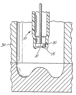
Figure 1 is a sectional view of a preform for
preparing the container of the present invention;
Figure 2 is an enlarged sectional view along lines
2-2 of Figure l;
Figure 3 is a partial sectional view taken through
a mold for molding the container of the present
invention and having associated therewith a preform
similar to the preform of Figure 1 which is to be
stretched and blown therein to form a container of the
present invention;
Figure 4 is an elevational view of a container of
the present invention formed in Figure 3;
Figure 5 is an enlarged sectional view taken along
lines 5-5 of Figure 4, with the corresponding sectional
view of Figure 2 superimposed therein in phantom;
~98~
90-203
Figure 6A is a partly schematic, enlarged sectional
view of the bottom portion and adjacent tubular body
portion of the container of Figure 4 in the empty
condition;
Figure 6B is a view similar to Figure 6A with the
container in the pressurized condition; and
Figure 7 is a schematic illustration of the bottom
portion and adjacent tubular body portion of the
container of Figure 4 in the empty condition
illustrating the radius of curvature of the hinge
portion and the radius of curvature of the conical
portion.
DETAILED DESCRIPTI _
Referring now to the drawings in detail, a plastic
parison or preform 10 is formed by injection molding
from a synthetic resin which can be biaxially oriented,
as for example poly (ethylene terephthalate). Tha
preform 10 has a neck portion 11 defining an opening 12
and it may be provided with external threads 13 to serve
as the site for attachment of a cap on the finished,
blow molded plastic container. The preform ]0 has a
tubular body portion 14 depending from the neck portion
11 and an integral bottom structure 15 depending from
the tubular body portion. The preform 10 has an outside
~9~
90-203
wall face 16 and an inside wall face 17. The inside
wall face 17 of the tubular body portion 14 is provided
with a thic]cened portion 18 which extends on-to bottom
structure 15 and is characterized by a plurality of
faces 19, which may be ~lat as shown or curved, with
terminal portions thereof l9a. Scallop-shaped segments
20 connect the terminal portions of each face 19. Three
or more of said flat or curved faces 19 may be used,
althou~h the hexagonal configuration of Figure 2 is
preferred. Alternately, for example, an octagonal
configuration may readily be employed. The bottom
structure 15 as shown in Figure 1 may be flat or may be
provided with an axially inwardly directed conical part
21 as shown in Figure 3.
Compared to the preform typically used according to
the known art, e.g. U.S. Patent 4,785,948, the length
"L" of thickened portion 18 is shortened and the depth
of the scallop-shaped segments 20 may be decreased as
well. The greater the length "L", the more does the
thickened portion of the base of the bottle blown from
the preform extend outward, to the side wall and thus,
the less the same portion will be oriented, meaning
undue brittleness. Similarly, the deeper the scallop
20, i.e., the thinner the wall at said scallops, the
~ore orientation will be obtained at the bottle regions
corresponding to the scallops.
--10--
2~ 8~i~
90-203
Thus, in order to obtain a high degree of
orientation at the heel 50 of the bottle, the length "L"
is red~ced so as to limit the corresponding thick
portions of the base to a region well inward of the
heel, see Figure 6 and the discussion hereinbelow.
As shown in Figure 1, thickened portion 18 includes
a lower portion 18a adjacent the bottom structure having
a wall thickness less than the wall thickness of the
adjacent thickened portion 18. It has been found that
this may be employed in order to save material costs
without loss of necessary properties in view of the
significant advantages obtained in accordance with the
present invention. Alternately, if desired, external
ribs may be provided on the preform as disclosed in the
aforesaid U.S. Patent No . 4,785,948.
The thus formed preform is brought to a temperature
at which blow molding can be accomplished which may be
done by heating a previously formed parison or forming
the hot parison in line with the blow molding operation
and suitably adjusting the temperature thereof. The
heated preform is then placed in a blow mold having the
configuration of the desired container, to be described
in greater detail below, as blow mold 30 shown in Figure
3 and w'nile blowing compressed air thereinto, the
interior side of bottom portion 15 is pushed down by
3~
90-203
movable means 31 to effect biaxial orientation. The
blow mold 30 shown in Figure 3 has an internal
configuration which allows the formation of a plastic
container 40 of the present lnvention (see Figure 4)
having a desired configuration as set forth herein.
Thus, blow molded plastic container 40 is formed
having a neck portion 41 defining an opening 42, a
bottom portion 43, a tubular body portion 44
interconnecting the neck portion 41 and the bottom
portion 43. ~eck portion 41 is provided with external
threads 45 to serve as the site for attachment of a cap
on the container, as with preform 10. The bottom
portion 43 has an internal, axially inwardly directed
generally conical part 46.
Figure 5 shows a preferred embodiment of the
present invention wherein the flat or curved faces form
a hexagonal configuration. Scallop-shaped segments 20
form the thinner portions 49a of the regularly
undulating cross-sectional configuration of the bottom
portion of the container with 49 representing the
thicker portions. Said segments may constitute parts of
circles, to facilitate manufacture.
Figures 6A and 6B represent partly schematic,
enlarged sectional views of the bottom portion 43 and
adjacent tubular body portion 44 of the container 40,
-12-
g8~
~0-203
wherein Figure 6A shows the container in the empty
condition and Figure 6B shows the container in the
pressurized condition. The heel portion 50 of bottom
portion 43 joins the bottom portion to the body portion
44. The bottom portion also includes a standing section
51 on which the container rests in the upright
condition, and a hinge portion 52 joining the conical
portion 46 to the standing section.
In accordance with the present invention, the wall
thickness of the hinge portion 52 is greater than the
wall thickness of the heel portion 50. Also, the wall
thickness of the heel portion 50 is greater than the
wall thickness of the body portion 44. Conical portion
46 includes an upper region 53, with the wall thickness
of the hinge portion 52 being greater than the wall
thickness of the upper region 53. The wall thickness of
the heel 50 may be thinner than the wall thickness of
the upper region. These relationships are shown
schematically in Figure 6A and are maintained in the
pressurized container of Figure 6B. Illustrative wall
tllickness ranges in the container of Figure 6A are:
heel - 0.35 mm, hinge - 3.2 mm; upper region of conical
portion - 2.2 mm; and body portion - 0.25 mm.
Thus, as clearly shown in Figure 6, the hinge
portion shows substantial thickening over the heel
-13-
2~9~4
90-203
portion. In accordance with the configuration of the
aforesaid U.S. Patent No. 4,785,948, eversion is
prevented by rendering the heel thic~er and rigid so
that in attempting to bulge axially outward under
pressure the base will be kept from doing so by the
rigidity of the heel. This means that the entire heel
region is rigid and any bulging of the heel plus conical
part 46 is prevented.
However, compared to the known art, in the
configuration of the present invention, the rigid
thickened portion is placed inwards to the hinge
portion, leaving the heel and adjoining side wall
flexible, even while preventing eversion. As a result,
upon pressurizing the bottle, the heel and side wall
will move outward and down forming an increased and more
stable standing section while eversion is still
prevented. The result is limited stability of the
bottle in the empty, unpressurized state and
substantially enhanced stability when pressurized due to
rolling out of the heel, all without eversion of the
base, which is precluded by the thickened hinge.
A thickened region will have reduced orientation,
even with the improved design represented by U.S. Patent
No. 4,785,948. This in turn means reduced impact
resistance, i.e., brittleness. Fortuitous impact loads
-14-
ç~
90-203
occur usually near the heel and hardly ever near the
center. Thus, brittleness near the center is tolerable,
while hrittleness near the heel is not. In accordance
with the present invention orientation at the heel and
therefore ductility are increased due to the placement
of the thickened portion well inward.
As schematically illustrated ln Figure 7 for the
container in the empty condition, conical portion 46
includes a radius of curvature X between upper region 53
and standing section 51, and heel portion 50 also has a
radius of curvature Y. A representative embodiment for
a two liter container in the empty condition is radius X
varying from 24 to 27 mm and radius Y varying from 17 to
20 mm. In accordance with the present invention the
ratio of radius X to radius Y should be from 0.75 to 2
and preferably from 1 to 1.6. It has been found -that
maintaining this ratio will enhance the stability of the
bottom portion of the container.
It is to be understood that the invention is not
limited to the illustrations described and shown herein,
which are deemed to be merely illustrative of the best
modes of carrying out the invention, and which are
susceptible of modification of form, size, arrangement
of parts and details of operation. The invention rather
is intended to encompass all such modifications w~ich
are within its spirit and scope as defined by the claims.
-15-