Note: Descriptions are shown in the official language in which they were submitted.
~9~
MOBILE WORK STATION FOR PAINTER
BACKGROUND OF THE INVENTION
In the process of painting, the painter placès the
container of paint on a surface and dips the brush or
paint roller into the container. The container may be
a paint can whenever a brush is used, and a pan
whenever a roller is used by the painter.
Since the container is bulky and prone to
spilling, thereby causing damage and requiring much
time wasted in clean up, the paint container is moved
infrequently. This necessitates constant travel by the
painter from the work area to the paint container,
which is tiring and inefficient. Also, the paint
container is usually placed on the floor increasing the
possibility oE spillage and other accidents. This
location is inconvenient for the painter who must bend
over to apply paint to the roller.
When brushing, the painter holds a paint can in
one hand and paints with the brush in the other hand.
This has the obvious disadvantages of restricting the
painter's movement besides being tiring and
inefficient, since a relatively small amount of paint
may be held in the paint can.
Furthermore, the painter's accessory tools and
equipment Isandpaper, wipes, tape, spackle, etc.) and
personal items (beverage, cigarettes, ash tray, etc.)
are not located near the work area; and thus the
painter must leave the work area to get these items.
Again, this is time consuming and inefficient.
Accordingly, it will be appreciated that painting
is often an unpleasant task for a "do-it yourself"
homeowner (and even for a professional palnter) because
the overall arrangement is inefficient; and thus a need
exists for a mobile work station to improve efficiency
-2- 2 ~ ~ 9
and make painting more convenient and less tiring and
time consuming.
The only prior art of which the applicant is aware
--- which is directed to a movable paint stand --~ is
United States Letters Patent No. 2,580,623 issued to
Wahl on January 1, 1952 in which there is disclosed a
stand to support a paint pail, the stand beinq mounted
on a carriage having rollers. The paint stand may not
be folded for ease of transport or storage, it does not
accomodate a paint pan for use with a paint rollPr and
it has no provisions to accomodate tools, accessories
or personal items.
Additionally, United States Letters Patent No.
2,290,450 issued to Renschin on July Z1, 1942 discloses
a telescoping tube to support a horizontal rod. The
rod takes the place of a man in holding paper to be
applied to a ceiling so that a single person can
perform the papering. The horizontal rod can be
replaced by a pan to hold a bucket of paint to
facilitate dipping a brush in the paint when painting a
ceiling. The device is not mobile and may not be
folded for use of transport or storage.
The applicant is also aware of the following prior
pate~nts:
Inventor(s) U.S. Patent No.
Clark 1,901,732
Conger 2,284,801
Hotton 2,981,549
Shackel 3,170,709
~eVitt et al 3,131,483
Burns 3,220,773
Swick., Jr. 3,759,599 ~ 37 ` `
Hines 4,119,044 ~ 6Z~
Schxeiner 4,363,496
Remington et al 4,535,897
Teachout 4,537,421
Cunningham 4,679,805~
Betts et al 4,690,417 ,1
Liegel 4,715,573 -~ ¦
Coote 4,728,065-
Kirkendall 4,796,909
2~9~
--3--
Grow D 183,425
Corini D 230,257
Salsgiver D 232,166
Daventry D 271,733
Luyk et al D 289,459
Bettress D 296,143.
As would be expected, these patents di.sclose a
wide variety of movable carts and tool stands for
various purposes. However, there is no disclosure nor
teaching that these carts may be used for, nor readily
adapted to, the unique requirements of a painter. A
painter should have ready and convenient access to the
paint, to the brushes, roller and other painting
accessories, and to the personal items of the painter.
To the best of our knowledge and belief, there is
no commercial product on the market, which provides a
mobile, versatile, articulatable, portable work station
for a painter.
Accordingly, it will be readily appreciated that
there exists a longstanding and cr.itical need for a
mobile work station for use specifically by painters,
wherein the mobile worlc station has the following
features and advantages: it may be moved easily and
conveniently to t.he immediate work area; it holds the
paint container (such as a pan) so that the paint is
less liable to be spilled; it holds the paint pan at a
convenient height, so that the painter does less
bending; it holds the necessary tools, accessories and
personal items; and it may be folded for ease of
storage and transport.
SUMMARY OF TE~E INVENTION
Accordingly, it is a principal object of the
present invention to alleviate the deficiencies and
disadvantages of the prior art by providing a painter's
mobile work station which holds a paint container (such
as a pan) as well as tools, accessories and personal
,
a
~4--
items, and which may be conveniently moved about on the
job.
It is another object of the present invention to
provide a painter's mobile work station which improves
efficiency, reduces travel of the painter between the
work area and the paint container, and is less time
consuming and tiring for the painter.
It is yet another object of the present invention
to provide a mobile work station which holds the paint
at a convenient height, so as to be less tiring to the
painter.
It is a further object of the present invention to
provide a mobile work station which is compact and
relatively lightweight, may be easily stored, and may
be carried to the job site.
It is still a further object of the present
invention to eliminate the placement of the paint
container on the floor, thereby decreasing the
possibility of spillage and accidents such as kicking
or stepping into the paint container.
It is additional object of the present invention
to enable the painter to use a larger, deeper paint pan
which holds a greater quantity of paint thereby
reducing the number of times the painter must interrupt
his work to refill the paint pan.
It is still a further object of the present
invention to provide a paint pan havin~ two shallower
ends and a deeper center portion thereby permitting the
painter to use a paint roIler when the painter is
positioned at either end of the paint pan~
Yet a further object of the present invention is
to enable the painter to place a five qallon bucket of
paint into an open well on the device which facilitates
using a paint roller with a larger bucket as opposed to
a paint pan.
; In accordance with the teachings of the present
-5_
invention, there is disclosed a mobile work station for
a painter or the like, wherein the mobile work station
is relatively lightweight and collapsible to facilitate
transport and storage. The mobile work station
includes a substantially rectangular ~rame having four
side walls~ The side walls form an open well
substantially in the center of the frame. A tray
having side walls and a bottom is provided; and the
tray is mounted in the open well in the rame; such
that a paint roller, paint pan, brushes and the like
may be disposed in the tray, and such that the work
station may be moved about by the painter on the job.
The mobile wor~ station further has four legs, each of
which has a first end and a second end, The first end
of each leg is mounted on the frame and is capable of
beinq pivoted, such that each leg has a first position
in which the leg is adjacent to (or nested within) the
frame, and such that each leg has a second position in
wh~ch the leg depends downwardly to support the frame.
Means are provided for securing each leg in both the
first and second positions; and casters are carried by
the second end of each leq, thereby facilitating the
convenient movement of the mobile work station on the
job. A cover is removably attached to the frame and,
when so attached, encloses the open well in the frame.
In this manner, the tray and the contents of the tray
are contained in the frame during storage and transport
of the mobile work station. When the cover is detached
from the frame, the cover may be disposed between the
legs (when the legs are in their second
downwardly-depending position) thereby further
supporting the legs and providing additional structural
integrity for the mobile work station. Additionally,
the cover may serve as a shelf during use of the mobile
work station. The work station is further provided
with a suitable handle means connected to the frame to
~ ~ ~ 9 ~ ~ ~
--6--
facilitate movement o~ the mobile work station by the
painter on the job.
~ iewe~ in another aspect, the present invention
provides a mobile work station for a pain-ter, wherein
the mobile work station is compact, lightweight and
readily portable, and wherein the mobile work station
may be quic~ly set up on the job and, thereafter, may
be quickly folded up for convenient storage. The
mobile work station includes a frame having a plurality
of legs and, preferably, the legs have respective wheel
means thereon. Means are provided for folding the legs
into a compact storage position on the frame, and means
are further provided for extending the leqs into a
downwardly-depending operative position relative to the
frame. The frame has an open well formed thereon, and
means provided for supporting a removable paint pan on
the frame suring use of the mobile work station When
~he mobile work station is not in use, a removable
cover is provided for the open well in the frame. When
the mobile work station is in use, however, the cover
may be disposed between the downwardly~depending legs
and removabl~ secure thereto, thereby providing
additional structural integrity for the mobile work
station during use thereof. In this position, the
cover also forms a shield, and (with the paint pan
removed from the frame) a relatively large paint can may
be received down through the open well in the frame and
supported by the shelf~
Preferably, the means to support the paint pan on
the frame comprises a tray removably received in the
open well in the frame. The tray has a plurality of
laterally-extending flanges supported on the frame; and
the tray is segmented to provide at least a first
recess for the paint pan and at least a first recess
for the paint pan and at least a second recess for
tools, accessories, and/or the painter's personal
7 ~ 3
items.
A handle is carried on the frame to facilitate
movement of the mobile work station by the painter.
The paint can has a shallow end and a deeper end,
respectively; and preferably, the first recess in the
tray is configured to assure that the shallow end of
the paint pan is disposed towards the handle, whenever
the paint pan is in the first recess in the tray.
Still other objects of the present invention will
become readily apparent to those skilled in this art
from the following description, wherein there is shown
and described a preferred embodiment of this invention.
Simply by way of illustration, the invention will be
set forth in part in the description that follows and
in part will become apparent to those skilled in the
art upon examination of the following or may be learned
with the practice of the invention. Accordingly, the
drawings and descriptions will be regarded as
illustrative in nature and not as restrictive.
BRIEF DESCRIPTION OF THE DRAWINGS
Fig. 1 is a perspective view of a first embodiment
of the mobile work station of the present invention.
Fig. 2 is a top plan view thereof.
Fig. 3 is an end view thereof.
Fig. 4 is a side view thereof.
Fig. 5 is a cross-sectional view taken along the
lines 5-5 of Fig. 2 (the thickness being exaggerated
for ease of illustration).
Fig. 6A is a perspective view of the mobile work
station of Fig. 1, showing the legs in a depending
position, and further showing he pivotal movement of
the legs through 270 to a stored position.
Fig. 6B is a perspective view of the mobile work
station of Fig. 1, showing the legs in the stored
2 0 1 9 9 6 ~
position in the open top of their tray.
Fig. 7 is a perspective view showing a person
holding the mobile work station of Fig. 1, wherein the
legs have been folded to their stored position.
Fig. 8 is a perspective view of the mobile work
station of Fig. 1, with the carrying strap disposed
thereon.
Fig. 9 is a perspective view of a second
embodiment of the mobile work station of the present
invention.
Fig~ 10 is a top plan view of the mobile work
station of Fig. 9.
Fig. 11 is a side view thereof.
Fig. 12 is an end view thereof.
Fig. 13 i5 an end view thereof, wherein a
transverse bar connects two legs.
Fig. 14A is a perspective view of the mobile work
station of Fig. 9, showing the legs in a depending
position, and further showing the pivotal movement of
the legs through 270~ to a stored position.
E'ig. 14B is a perspective view of the mobile work
station of Fig. 9, showing the legs in the stored
position in the open top of the tray.
Fig. 15 is a perspective view of a third
embodiment of the mobile work station of the present
invention.
Fig. 15A is a perspective view of the embodiment
of Fig. 15 mounted on a wall for storage.
Fig. 15B is a perspective view of the embodiment
of Fig. 15 being carried by a userO
Fig. 16 is a perspective view of the underside of
the embodiment of Fig. 15.
Fig. 16A is a cross section view along the lines
16A-16A of Fig. 16.
Fig. 16B is a side elevation view of the
embodiment of Fig. 15l showing the legs placed in the
9 2 ~
downward depending position.
FigsO 17A-17C are perspective views of the
embodiment of Fig. 15 showing one leg ~in broken lines)
pivotally mounted in the frame. The other legs have
been omitted for ease and illustration.
Fig. 18 is a perspective view of the embodiment of
Fig. 15 showing the work station supported on its legs.
Fig. 19 is a perspective view of the embodiment of
Fig. 15 showing the cover removed.
Fig. 20 is a perspective view of the embodiment of
Fig. 15 showing the cover disposed between the legs,
thereby forming a shelf, and thereby providing
additional structural rigidity for the mobile work
station.
Fig. 21 is a perspective view of the embodiment of
Fig. 15 showing the device available for use.
Fig. 22 is a perspective view of the embodimenl of
Fig. 15 in a typical use.
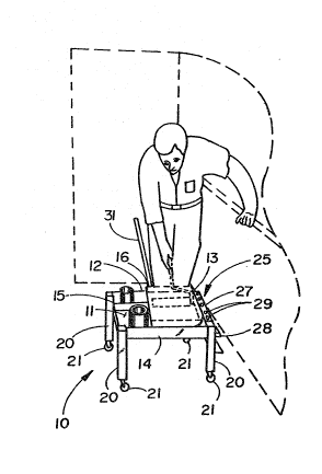
Fig. 22A is a cross sectional view taken along the
lines 22A-22A of Fiq. 22.
Fig. 22B is a cross sectional view of an al~ernate
embodiment of the paint pan.
Fig. 23 is a perspective view of the embodiment of
Fig. 15 showing large containers stored on the shelf.
Fig. 24 is an exploded perspective view of the
embodiment of Fig. 15.
Fig. 25 is a cross sectional view taken across the
lines 25-25 of Fig. 24,
Fig. 25A is a cross sectional view taken across
the lines 25A-25A of Fig. 23.
Fig. 26 is a perspective view of the embodiment of
Fig. 15 showing a removable receptacle attached to the
frame of the work station.
FigsO 27A-27D are perspective views of the
embodiment of Fig. 15 showing the removal of the tray
and the placement of a large container on the cover
-10~
which is serving as a shelf.
DESCRIPTION OF THE PREFERRED EMBODIMENTS
With reference to Figs. 1-5, there is illustrated
a mobile work station 10 for a painter or the like.
The device has a rectangular tray 11 with side walls
12, 13, 14, 15 to form an open top receptacle. One or
more dividers 16 are disposed within the tray to form
compartments therein. The compartments are of
dimensions such that equipment, such as a painter's pan
for use with a paint roller applicator or a one (1)
gallon can of paint, can be easily and securely placed
in the compartment. Also, the compartment may be used
for access~ry equipment (such as sandpaper, wipes,
paint brushes, tape, etc.) or for personal items
(beverage, cigarettes, ash tray, etc.). As shown in
E'ig. 2, the tray may have a continuous surface, it may
be a mesh-like surface or it may be continuous in one
compartment and mesh-like 19 in another. For example,
the compartment in which the pan for use with a roller
applicator is preferably mesh-like 19 because there is
a greater probability of paint spilling in this
compartment and the mesh-like structure is less
difficult to clean. Furthermore, the mesh~like
structure reduces the total weight of the work station.
The work station has four legs 20, each leg having
a first end and a second end. The first end of each
leg is pivotally mounted on the tray 11. As shown in
Fig. 6A, the legs may pivot through 270 to a first
position in which the leg 20 is ad~acent to the tray 11
and is stored in the open top of the tray 11. The legs
in the stored position are shown in Fig. 6B. The legs
20 also have a second position in which the legs 20
depend downwardly from the tray 11 to support the tray
11. Means are provided to secure the legs 20 in both
11- 2~9~
first and second pOSitiOIIS SO the legs may be secure in
the collapsed or working position respectively.
Preferably, the leg height is approximately 13 in.
to 18 in. as being most convenient with respect to
reducing bending by the painter and obtaining a stable
work station 10.
Casters 21 are carried by the second end of each
leg 20 to enable the work station 10 to be easily
rolled over a surface to facilitate movement of the
work station and reduce movement and travel by the
painter.
A handle 31 is also provided which may be
removable or may otherwise be foldable to allow easy
transport and storage. The handle 31 may be a
painter's "shorty pole" whlch may be threadably
connected with a complementary threaded fitting on the
work station 10. The handle allows the painter to
easily pull or push the work station 10 safely as the
painter progresses from one work area to another work
area. In addition, a deeper paint pan capable of
holding more paint may be used without the risk of back
injury to the painter or spillage of the paint.
A removable shelf 25 may also be provided as a
receptacle for painter's tools and sundry items. The
shelf has a back 26, at least one shelf 27, sides 28
and means for removably attaching the shelf 25 to the
work station 10. If desired, the shelf may have a
hinged or removable cover.
As shown in Fig. 7, the work station 10 is
relatively lightweight and is easily carried by a
person in the collapsed position. The handle 31 may be
conveniently placed across one of the compartments of
the tray 11. A carrying strap 32 may be removably
disposed about the tray 11 with the legs 20 in the
first position adjacent to the inside of the tray 11,
as in Fig. 8.
-12~
Figs. 9-14R show a second embodiment (constituting
a first alternate embodiment) of the work station 10 in
which one leg 36 is pivotally mounted on the second
side wall 13 substantially at the corner of the second
side wall 13 and the first side wall 12. A second leg
37 is pivotally mounted on the fourth side wall 15 near
the first side wall 12. The third leq 38 and fourth
leg 39 are pivotally mounted on the third side wall 14;
the third leg 38 is near the second side wall 13 and
the fourth leg 39 is near the fourth side wall ~5. The
legs 36-39 are capable of pivoting substantially 270
(Fig. 14A) such that the legs 36-39 have a first
position in which the legs 36-39 are stored in the open
top of the tray 11 and such that the legs 36-39 have a
second position in which each leg 36-39 depends
downwardly from the tray 11 and supports the tray 11.
In the stored position, the first leg 36 is disposed
adjacent to the second leg 37 as shown in Fig. 14B.
As shown in Figs. 13, 14A and 14B, leg 38 and leg
39 may be connected by a transverse bar 40 therebetween
so that both legs 3~, 39 are moved simultaneously
between the first stored position and the second
supporting position.
The first alternate embodiment may also have
compartmen~s and removable shelves.
With reference to Figs. 15-25, there is disclosed
a third embodiment (constituting a second alternate
embodiment) of the present invention, which is
preferred for commercial painters and painting
contractors. This third embodiment comprises a mobile
work station 10' which is somewhat larger than the
previously described embodiments. The mobile work
station 10l is capable of handling larger paint pans
and larger containers of paint, plaster, spackling
material and the like --- all of which are more likely
to be used by a professional or commercial painter or
2 ~ 5
-13-
painting contractor. The work station 10' is compact,
may be folded into a relatively small size, and is
relatively lightweight. Accordingly, the mobile work
station 10' may be easily stored in the shop or in a
van, may be easily carried to the job site, and may be
easily set up ~or use on the job.
The work station 10' has a frame 50 which has side
walls 51 to form an open well 52 substantially in the
center of the frame 50. A tray 53, having side walls
and a bottom, is mounted in the well 52. The side
walls of the tray have sufficient height (i.e. the tray
in deep enough~ for the disposition of a paint roller,
a paint pan, brushes and the like within the tray.
Since this embodiment is adaptable for commercial
applications, the tray can accomodate large paint pans,
large rollers and five gallon containers of paint.
A plurality of legs 54 (preferably four) are
provided, each leg 54 having a first end 54A and a
second end 54B. The first end 54A of each leg 54 is
mounted on the frame 50; and each leg 54 is capable of
being pivoted, such that each leg 54 has a firsk
position in which the leg 54 is adjacent to the frame
50, and further has a second position in which each leg
54 depends downwardly to support the frame 50. (Figs.
17A-17C).
Means are provided to secure each leg 54 in the
first position and in the second position,
respectively. The securing means may be detent, a bolt
and nut, a brace or other means known to persons
skilled in the art. The second end 54B of each leg 54
may have a caster 55 thereon to improve the mobility of
the work station 10'.
A cover 56 is removably attached to the frame 50
such that, when attached, the cover 55 encloses the
open well 52 i.n the frame 50. Thus, the tray 53 and
any contents of the tray 53 are contained within the
-14- 2~
frame 50, and the mobile work station 10' may be
transported conveniently. (Figs. 18~19).
When the cover 55 is detached from the frame 50,
the cover 55 may be disposed between the depending legs
54 (when the legs are in their secondl dep~nding
position) and the cover 55 may be removably secured to
the legs 54. (Figs. 20-21). In such a manner, the
cover 55 further supports the legs 54 in their
downwardly-depending second position and provides
additional structural integrity for the mobile work
station l0'. Moreover, in this disposition between the
legs 54, the cover 55 also serves as a shelf for
carrying articles thereon.
As shown in Fig. 23, the tray 53 may be removed;
and the mobile work station 10' may be used with large
containers of supplies and materials, such as a
five-gallon paint can, which is supported by the cover
55 in its role as a shelf disposed between the legs S4.
Also provided is a means for moving the mobile
work station 10'. This may be a rigid handle 57 which
is connected to the frame 50. Alternately, the handle
may be a flexible means attached to the frame 50. The
means ~or moving the mobile work station 10' is
positioned in a manner so that it may be easily grasped
by the painter. The rigid handle permits the painter
to either push or pull the mobile work station 10' more
easily than the flexible means, but the flexible means
contributes to compactness. The handle 57 may also
serve to carry and transport the device 10' when the
device has been collapsed after use.
The ~ray 53 has a bottom 58 and side walls 59.
The top of each side wall 59 has a flange 60 formed
~hereon (Fig. 24 and; 25). The flange 60 may be
supported by the frame 50 so that the tray 53 may be
disposed in the well 52 in the frame 50. In this
manner, the tray 53 may be easily placed in the frame
-15-
50 and removed from the frame 50 when desired. This
permits ease of cleaninq of the tray 53 and also
permits removal of the tray 53 when the cover 56 is
being used as a shelf to support large containers (as
previously described). The tray 53 may be fabricated
of metal or plastic.
The dimensions of the tray 53 permit the placemenk
of a standard painter's pan 61 ~ithin the tray 53 ~Fig.
22). Preferably, the tray 53 is configured such that
the positioning of the painter's pan 61 in the tray 53
is limited, and such that the pan 61 must be oriented
towards the handle 570
The paint pan 61 has a deeper end 62 and a
shallower end 63, and a paint roller, may be dipped in
the paint at the deeper end 62 and rolled towards the
shallower end 63 to remove excess paint. This is more
properly accomplished when the painter is positioned
towards the shallower end 63 of the pan 61. Since the
painter should be positioned near the handle 57 on the
mobile work station 10', the orientation of the paint
pan 61 is such that the shallower end 63 of the paint
pan 61 is towards the handle 57, and the deeper end of
the pan 61 is away from the handle 57. The dimensions
of the tray 53, preferably, do not permit the paint pan
61 to be disposed in the tray 53 in any oth~r
orientation.
A metal mesh grid 70 may also be placed on the
shallow end 63 of the pan 61 to improve the removal of
excess paint from the roller before applying paint to a
surface. The grid 70 is more efficient in removing the
excess paint and the disposition of the grid 70 permits
the excess paint to drain into the pan 61. The grid 70
usually has legs at both ends such that one end maybe
clipped to the pan 61 or to the tray 53 and the other
end may rest on the pan 61. A pair of slots may be
disposed in the tray 53 or the frame 51 to receive the
-1~- 2~
legs on the grid 70 and to secure the grid 70 in a
desired position. Alternately, ~Fig. 27C) the grid 70
may be disposed inside the five gallon bucket 71 with
the legs on one end of the grid 70 attached to the
upper lip of the bucket 71 and the other end extending
into the bucket 71. In this manner, the painter may
immerse the roller into the paint in the bucket, remove
the excess paint on the grid 70 and apply the roller to
the surface to be painted. This permits the painter to
paint more rapidly without transferring the paint to a
paint pan 61.
Referring to Fig. 22B, in an alternate embodiment,
the paint pan 75 has two shallower ends 76 and a deeper
center portion 77. Thus, the painter may use the paint
roller efficiently with the paint pan 75 when the
painter is positioned at either end of the paint pan
75. It is unnecessary for the painter either to move
around the work station 10' or to turn the work station
10' so that the paint roller may be rolled on the
shallower end 76 to remove excess paint. The work
station may be provided with a handle 57 at both
opposite sides so that the work station may be easily
moved by the painter when using the paint pan 75 with
two shallower ends 76.
The tray 53 also may have a removable compartment
64 which may be disposed adjacent to the painter's pan
61. This compartment 64 may be used for painting
accessories such as brushes, sandpaper, etc. and also
for personal items of the painter.
The mobile work s-ta~ion 10' may also be provided
with one or more removable receptacles 65 with means
for attachment to the work station 10'. The means for
attachment may be posts extending upwardly from the
frame 50 which engage openings in the receptacle 65.
Other means known to persons skilled in the art may
also be used. As shown in Fig. 26 the receptacle 65
2~9~
-17
has a back 66, two sides 67, and at least one shelf 68.
The receptacle 65 may be used to store the painter's
tools, brushes, and similar items and may also be used
for storage of the painter's personal articles.
Accordingly, it will be appreciated that the
present invention readily achieves its objectives. The
work station is mobile; provides a convenient means for
holding paint, accessory equipment, tools and personal
items; is relatively lightweight; and is easily
transported and stored. It will be appreciated that,
althouqh use by painters has been identified, other
workmen and homeowners will find the mobile work
station of the present invention of great utility for
general movement of e~uipment, tools and other
materials. Also, it will be appreciated that the
mobile work station may be rectangular or have other
configurations adaptable to specific purposes; and,
although the drawings show a work station having four
leys, other confi~urations may be stably supported with
other than four legs.
Obviously, many modifications may be made without
departing from the basic spirit of the present
invention. Accordingly, it will be appreciated by
those skilled in the art that within the scope of the
appended claims, the invention may be practiced other
than has been specifically described herein.