Note: Descriptions are shown in the official language in which they were submitted.
202001
FIELD OF THE INVENTION
This invention relates to self-propelled mechanical
street sweepers utilizing brushes and a mechanical elevator for
conveying debris into a hopper.
BACKGROUND OF THE INVENTION
A typical self-propelled mechanical street sweeper
comprises a cab and a chassis having a sweeper mechanism mounted
thereon. The sweeper mechanism generally comprises a pick-up
brush mounted at the rear of the chassis, a pair of gutter brooms
suspended from the sides o~ the chassis for sweeping debris into
a windrow for pick up by the pick-up brush, a conveyor or
elevator for conveying the debris up and away from the pick-up ,
brush, a hopper ~or storing the debris, and a mechanism for
dumping the hopper.
It has been found that unless the pick-up brush is
mounted reasonably close to the rear wheels of 'the sweeper
chassis, some of the debris swept towards the pick-up brush by
the gutter brushes i.s 1e~t behind on the road as 'the sweeper
turns corners. The reason for this problem is that the swath of
the rear pick-up brush is not in complete conformity with the
path of the vehicle, as the vehicle negotiates corners. This
problem can be overcome by mounting the elevator between the rear
wheels of the sweeper, and the pick-up brush right behind the
rear wheels. However, standard production truck chassis tend to
have a through rear axle. Therefore, in order to provide
sufficient clearance for the elevator, most prior art sweepers
are mounted on a custom-made chassis having a pair of stub rear
axles. Custom chassis are, however, expensive to build in small
volumes. Additionally, most custom chassis sweepers are built
for slow speed use only, because of the difficulties associated
with certifying a custom chassis for highway speed. As a result,
driving such sweepers long distances between jobs tends to be a
slow and uncomfortable process.
Attempts have been made in the past to create a sweeper
which can be mounted on an OEM or production truck chassis, so as
to avoid the need to design and manufacture a custom chassis.
One such prior art design includes a 'trailer for housing the rear
pick-up brush which is pulled on casters behind the truck
chassis, a reduced-width elevator which fits in between the frame
of the chassis, and an auger mechanism for channelling the dirt
swept up by the rear brush into the reduced-width elevator.
However, because the pick-up brush of this prior art design
protrudes too far to the rear, there exists a di.scon.formity
- 2 -
20~~2fli
between the swath of the sweeper and the path of the vehicle as
it turns a corner, resulting in less effective sweeping action
than sweepers utilizing custom truck chassis. Also, in the case
of this prior art design, there exists the risk that its pick-up
brush trailer could be damaged by impact against a curb as the
sweeper turns a corner.
SUMMARY OF THE INVENTION
The present invention provides a mechanical sweeper
design, utilizing a modified production truck chassis, which
overcomes the disadvantages of the prior art. The street sweeper
made in accordance with present invention produces sweeping
action comparable to that of a sweeper utilizing a custom
chassis. However, because the subject sweeper utilizes a
production truck chassis,~it is less costly to build yet is
capable of crui.si.ng comfortably at highway speeds.
The street sweeper of the subject l.nvention utilizes a
production truck cab and chassis having a pair of longitudinally
extending frame beams, a through rear axle extending transversely
thereto, and a pair of rear wheels mounted to the ends of the
rear axle, wherein the frame beams have been modified by removing
rear portions thereof extending behind the rear axle. The
sweeper includes side brush means mounted to the chassis forward
of the rear wheels and rotatable about a near vertical axis for
- 3 -
CA 02020201 1999-09-22
Gathering debris from the sides of the path of travel of
the sweeper and directing it inwardly to create a windrow
of debris underneath the sweeper along the longitudinal
axis thereof, pick-up brush means mounted behind the rear
wheels and rotatable about a horizontal axis for picking
up the windrow of debris, conveying means mounted
forwardly of the pick-up brush means adjacent the rear
axle for conveying upwardly the debris picked up by the
pick-up brush means, hopper means mounted forward of the
conveyor means for receiving and storing the debris
conveyed thereby, dumping means for dumping the hopper,
and rear suspension means. The conveying means has a
uniform width throughout its length, and is approximately
the same width as the pick-up brush. The rear suspension
means is mounted above and forwardly but not rearwardly
of the rear axle. The rear suspension means comprises
bias means mounted between the frame and the rear axle
for biasing the rear axle away from the frame of chassis,
and connecting arm means pivotally mounted to the frame
at a location in front of the rear axle for connecting
the rear axle to the frame beams.
The bias means is preferably a rubber pad mounted between
the rear axle and the frame, which acts as both a spring
and a shock absorber. The connecting arm preferably
functions as both a trailing arm and a torsion bar. In a
preferred embodiment, the connecting arm consists of the
forward portion of the leaf spring supplied with the
production truck chassis.
- 4 -
2~2~~Q~
In the presently preferred embodiment of the invention,
the street sweeper is further provided with a vacuum pick-up
means having a vacuum head mounted behind the pick-up brush means
for picking up any debris left by the pick-up brush means. The
vacuum pick-up means comprises a vacuum pump connected to the
vacuum head via a conduit.
The dumping means of the presently preferred embodiment
is a high lift dumping means having telescoping arms for lifting
the hopper means and dumping it from an elevated position. The
high lift dumping means of the subject invention preferably dumps
the hopper means to the side o.f the sweeper.
BRIEF DESCRIPTION OF THE DRAWINGS
The invention will now be described, by way example
only, with reference to the accompanying drawings, i.n which like
numerals refer to like parts, and i.n which:
Figure 1 is a side elevational view of a street sweeper
embodying the subject invention;
Figure 2 is a side elevational view of the rear
suspension means of the present invention;
- 5 -
~0~0~01
Figure 3 is a partial elevational rear view
illustrating the frame, rear suspension means, and rear axle of a
street sweeper embodying the subject invention;
Figure 4 is a schematic cross-sectional view of the
presently preferred embodiment of the invention comprising the
vacuum pick-up means;
Figure 5 is a partial rear view illustrating the high
lift dumping means of the presently preferred embodiment of the
invention in its fully lowered position;
Figure 6 is a partial rear view illustrating the high
lift dumping means of the presently preferred embodiment of the
invention in a position between its fully lowered position and
its fully elevated position;
Figure 7 is a partial rear view illustrating the high
lift dumping means of the presently preferred embodiment of the
invention in its fully elevated dumping position;
Figure 8 is a detailed view of a portion A-1 of Figure.
7; and
Figure 9 is a sectional view taken along line Z-Z of
Figure 8.
- 6 -
~~~fl2'Q~.
DETAILED DESCRIPTION OF THE PREFERRED EMBODIMENTS
Figure 1 illustrates a street sweeper 10 embodying the
subject invention. Street sweeper 10 utilizes a production truck
chassis comprising a cab 12, chassis frame 14, front wheels 16,
front suspension 18, engine and drive train (not shown), rear
axle 19 and rear wheels 20. Those portions of the chassis frame
14 extending rearwardly of the rear axle 19 have been removed.
Mounted unto production truck frame 14 is a custom
sweeper mechanism shown generally as 22 which consists of a
number of components mounted unto a sweeper frame which is
welded, bolted or otherwise fastened to chassis frame 14. The
sweeper frame comprises longitudinal frame members 24, cross bar
26, angular frame member 28 and rear upright member 30.
Dirt hopper 32 is pivotally coupled to frame upright 30
by means of a pair of spaced lift arrns 34. Pick-up brush 36 is
mounted behind rear wheels 20 by mounting means 38. Gutter
brushes 40 are suspended from chassis frame 14 or sweeper
longitudinal frame members 24 by brush suspension means 42.
Elevator 44 is mounted between pick-up brush 36 and
rear axle 19 and extends at an angle between the front of pick-up ,
brush 36 and the back of dirt hopper 32. The rear panel of dirt
hopper 32 is provided with an opening which permits the elevator
CA 02020201 1999-09-22
44 to direct dirt and other debris into dirt hopper 32.
Elevator 44 has a uniform width throughout its length,
which width is substantially the same as the width of
pick-up brush 36. Elevator 44 comprises a chute or pan
against which squeegees mounted on a pair of squeegee
carriers or straps slide so as to move the debris
upwardly in the chute as the squeegees are moved
upwardly.
Means (not shown) are provided for lowering gutter
brushes 40, pick-up brush 36 and elevator 44 into
sweeping mode and for raising such components into
transport mode. Hydraulic pump (not shown), powered by
auxiliary engine 50, drives hydraulic motors (not shown)
which turn gutter brushes 40, pick-up brush 36, and
elevator 44. Hydraulic oil tank 52 supplies hydraulic
oil to the hydraulic pump. Water tank 54 is located at
the rear above pick-up brush 36.
Dirt hopper 32 is dumped rearwardly by operation of a
pair of hydraulic cylinders 56, which extend between the
sweeper frame and lift arms 34. The solid lines
illustrate dirt hopper 32 and lift arms 34 in their rest
position, and the broken lines illustrate dirt hopper 32
and lift arms 34 in their dump position. As dirt hopper
32 is dumped, a gate mechanism comprising hopper gate 58,
hydraulic cylinders 60 and linkage 62 function to close
gate 58 over the opening in the rear of dirt hopper 32 as
it is elevated upwardly and rearwardly. As dirt
- g -
~o~o~o~
hopper 32 swings past top dead center, hopper cover 64 slides
open, allowing the debris in dirt hopper 32 to slide out into a
suitable waste receptacle.
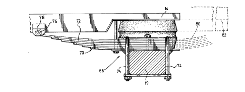
The sweeper of the present invention also comprises
rear suspension means shown generally as 66, compri.si.ng bias
means for biasing the rear axle away from the chassis, preferably
in the form of a pair of rubber pads 68 which are mounted above
rear axle 19 directly below longitudinal chassis frame members
14, and connecting means 70 for connecting the rear axle to the
chassis.
Referring now to Figures 2 and 3, depicting a preferred
embodiment of rear suspension means 66, connecting means 70 may
comprise the forward portion of a conventional leaf spring 72
coupled to rear axle 19 by means of U-bolts 74 and pivotally
coupled to a forward portion of longitudinal frame member 14 by
pins 76 surrounded by grommet 78. Modified leaf spring 72 no
longer functions as a spring, but rather, it functions as both a
trailing arm and a torsion bar. Rubber pads 68 preferably take
the form of Timbren (trade mark) or other suitable commercially
available rubber suspension cushions. As shown in the dotted
lines, the rear portion 80 of leaf spring 72 and rear portion 82
of chassis frame 14 have been removed, in order to provide
clearance for full-width elevator 44.
_ g _
~0~020~
The modifications made to 'the production -truck chassis
in accordance with the present invention produce a sweeper
chassis having both a frame and a rear suspension which no longer
extends appreciably rearwardly of the rear axle 19. These
modifications enable full width elevator 44 to be mounted
immediately to the rear of rear axle 19, and pick-up brush 36 to
be mounted not too far behind rear axle 19, resulting in
reasonably close conformity between the swath of the pick-up
brush 36 and the path of the vehicle.
In operation, the sweeper 10 is placed in sweeping mode
by lowering the elevator 44, pick-up brush 36 and gutter brushes
40, and activating their hydraulic motors. As the sweeper 10
travels down the road in sweeping mode, the gutter brushes gather
dirt and debris from the sides of the path of travel of the
vehicle, and direct the dirt inwardly so as to form a row or
windrow of dirt in the path of the pick-up brush 36. Pick-up
brush 36 sweeps the debris forwardly onto elevator 44. The
elevator 44 carries the debris upwardly and discharges it at its
uppermost end into dirt hopper 32. When dirt hopper 32 becomes
full, it may be dumped rearwardly by activating hydraulic
cylinders 56, which elevate lift arms 34 upwardly and rearwardly.
As lift arms 34 are elevated, hydraulic cyl9.nders 60 activate
hopper gate 58 so as to close the opening in the rear of dirt
hopper 32 and thus prevent premature discharge of the hopper
contents. As dirt hopper 32 is elevated past top dead center, '
- 10 -
CA 02020201 1999-09-22
hopper cover 64 opens, allowing the debris to slide out
of dirt hopper 32 into a suitable waste receptacle.
Because pick-up brush 36 is mounted only a short distance
behind rear axle 14, the swath of rear brush 36 is in
close conformity with the path of vehicle, as the sweeper
turns corners. As a result, pick-up brush 36 picks up
the entire windrow of debris formed by gutter brushes 40,
at all times. In order to convert the sweeper 10 into
transport mode, gutter brushes 40, elevator 44 and rear
brush 36 are elevated into their transport position.
Because of the operation of rubber pads 68 of rear
suspension means 66, the sweeper of the present invention
is capable of cruising comfortably at high speeds.
In the preferred embodiment of the invention, the
production truck chassis is an Isuzu TM chassis suitable
for carrying a three cubic yard dirt hopper, but other
standard OEM production truck chassis may be used,
provided that the above-described modifications to the
frame and rear suspension are made.
While in the preferred embodiment of the invention the
rear suspension means comprises a modified leaf spring
and a rubber pad, it should be apparent that the
production leaf spring could be removed altogether and
replaced by a trailing arm or torsion bar which extends
forwardly of but not appreciably behind the rear axle.
As well, a coil spring or air bag suspension
- 11 -
system could be used instead of a rubber pad, provided that such
system does not extend rearwardly of the rear axle.
It should also be understood that while the sweeper
illustrated and described above includes a hopper dump mechanism
which dumps to the rear, other types of hopper dump systems, such
as a side dump system, could be used. Additionally, while Figure
1 depicts a sweeper having an auxiliary engine which powers the
hydraulic pump, it is possible to eliminate the auxiliary engine
by coupling the hydraulic pump to a power-take off connected to
the camshaft or crankshaft of the vehicle's engine.
Figures 4 to 9 illustrate the presently preferred
embodiment of the invention. Referring first to Figure 4, street
sweeper shown generally as 100 comprises dirt hopper 110, pick-up
brush 115, elevator 120, and vacuum pick-up means shown generally
as 125. Dirt hopper 110, pick-up brush 115 and elevator 120 are
similar to dirt hopper 32, pick-up brush 36 and elevator 44,
respectively.
Vacuum pick-up means 125 comprises vacuum head 130 ,'
which is mounted directly behind pick-up brush 115. Vacuum head
130 is evacuated by vacuum pump 135 via conduit 140. Vacuum pump
135 preferably comprises a centrifugal fan having an intake port
145 and an exhaust port 150. Conduit 140 is attached at one end
to intake port 145 and vacuum head 130 at its other end. Exhaust
- 12 -
202fl2fli
port 150 preferably empties into dirt hopper 110. Alternatively,
exhaust port 150 could empty onto elevator 120 or in front of
brush 115.
In operation, pick-up brush 115 sweeps most of the dirt
to elevator 120 which then transports it to dirt hopper 110.
However, in most cases pick-up brush 115 is not 100% efficient,
and some dirt remains on the ground after pick-up brush 115
passes. This remaining dirt is sucked up into vacuum head 130
and is carried in a stream of air through conduit 140 and vacuum
pump 135 to be deposited into dirt hopper 110. Because head 130
is located behind pick-up brush 115, only a small amount of dirt
remains to be gathered by the vacuum pick-up means. Thus, the
power requirements for vacuum pump 135 are far less than in the
case of vacuum street sweepers which rely solely on vacuum power
for picking up refuse.
Referring now to Figures 5, 6 and 7, the presently
preferred embodiment of the subject street sweeper is preferably
provided with high lift side dumping means shown generally as
200. High lift dumping means 200 comprises a pair of telescoping
arms shown generally as 210, which are formed from hollow tubular t
post 214 and I-beam 216 configured to be slidingly received
within tubular post 214. Tubular post 214 is attached at its
bottom end to frame members 220. Dirt hopper 212 is pivotally
attached to I-beam 216 at hopper pivot point 222.
- 13 -
CA 02020201 1999-09-22
Dirt hopper 212 is elevated by hydraulic lift cylinder
218 which is attached at one end to frame member 224 and
at its other end to hopper flange 226. Roller 230 is
attached to the bottom of hopper 212 and bears against
ramp 228 attached to the side of tubular post 214. When
hydraulic lift cylinder 218 is extended, dirt hopper 212
is elevated, thereby extending I-beam 216 out of tubular
post 214. Roller 230 and ramp 228 ensure that hopper 212
does not hit cylinder 218 while telescoping arms 210 are
being extended. Ramp 228 is also shaped to pivot hopper
212 slightly in the direction in which it will be dumped.
To aid the smooth extension and retraction of telescoping
arms 210, low friction lining 244 is interposed between
I-beam 216 and tubular member 214 as shown in Figure 8.
This lining permits I-beam 216 to slide freely within
tubular member 214.
Stop members 240 and 242, attached to the inside of
tubular post 214 and to I-beam 216, respectively, as
shown in Figures 8 and 9, stop the extension of
telescoping arms 210 at a reselected height, chosen to be
higher than the height of a standard dump truck or
receptacle into which the hopper is to be dumped. The
height of ramp 228 is selected to ensure that the
extension of telescoping arms 210 is stopped before
roller 230 reaches the top edge thereof.
Hydraulic cylinder 218 is mounted to flange 226, which
-14-
2D~~~~~
is located between hopper pivot point 222 and the centre of
gravity of hopper 212. The stroke of hydraulic lift cylinder 218
is selected to ensure that it has a sufficient amount of stroke
remaining when the extension of telescoping arm 210 is stopped,
to rotate hopper 212 about hopper pivot point 222.
To prevent the street sweeper from tipping over when
the hopper is dumped, it is important to keep the centre of
gravity of dirt hopper 212 from rotating past hopper pivot point
222. The stroke of cylinder 218 is selected to prevent
over-rotation of the centre of gravity of hopper 212, assuming
that telescoping arms 210 have been extended fully. However,
should telescoping arms 210 stick, over-rotation i.s prevented by
an over-rotation linkage comprising steel bar 232, and loop
member 236. Steel bar 232 is welded on top of I-beam 216 and
loop member 236 is pivotally attached to steel bar 232 at point
234 and is attached to dirt hopper 212. on pin 238.
In operation, dirt hopper 212 is elevated by extending
hydraulic cylinder 218, which causes t-beam 216 to extend out of
tubular post 214. Roller 230 and ramp 228 keep hopper 212 from
contacting 218, and ramp 228 pivots hopper 212 slightly as i.t is
being elevated. When the extension of telescoping arm 210 is
stopped by stop members 242 and 240, hopper pivot point 222
cannot be raised further; however, hydraulic lift cylinder 218
still has some stroke left and pushes up on flange 226 to pivot
hopper 212 about hopper pivot point 222. Over-rotation of hopper
- 15 -
212 is prevented by loop member 236, and hopper 212 is held in
this dumping position as shown i.n Figure 7. Retracting hydraulic
cylinder 218 causes hopper 212 to pivot back to its level
position. A spring may also be interposed between point 234 and
pin 238 to assist the return of hopper 212 into its level
position. Hopper 212 then slowly returns to its lowered position
as shown in Figure 5.
By dumping from an elevated position, high lift dumping ;
means 210 permits the contents of dirt hopper 212 to be dumped
directly into a high-sided dump truck.
In a variant of the presently preferred embodiment, the
structure of the high lift dumping means may be varied to dump
the dirt hopper to the rear of the street sweeper. The
telescoping arms and the hydraulic lift cylinder would in this
case have to be mounted to the rear of the street sweeper.
It should therefore be apparent to persons skilled in
the art that various modifications and adoptions of the structure
described above are possible without departing from 'the spirit of
the invention, the scope which is defined in the appended claims.
- 16 -