Note: Descriptions are shown in the official language in which they were submitted.
: '
SUREACE-PATTERNED POLYBUTYLENE TEREP~T~ALATE
RESIN MOLDED ARTICLES AND PROCESS FOR PREPARING
SUC~ MOLDED ARTICLES
EIELD OF INVENTION ~ ;
The present invention relates to polybutylene
terephthalate resin molded articles having a graphic
and/or indiria pattern (including letters, figures,
symbols and the like) ormed on a surface thereof, -~
and to processes for preparing such molded articles.
BACKGROUND AND SUMMARY OE TUE INVENTION
Molded resin articles have been decorated in
the past with graphic and/or indicia patterns (such
as letters, igures, symbols and the Like) using
known foil-decorating techniques. According to the
foil-decorating technique, a molded
surface-patterned article is prepared by placing in
a~mold cavity a resin film bearing a selected
graphic and/or indicia pattern, filling the mold
cavity with a molten resin (or a resin prepolymer)
and then compressing the thus obtained molded ~ -~
article under heat and pressure to integrate the ~-
film onto a surface of the molded article. In the
caselof therimosetting resins, this heat and pressure'
treatment serves to cause the resin to react further.
The foil-decorating~technique has been used
extensively to decorate the surfaces of molded
artlcles formed of thermosetting resins (e.g.
` 2~
melamine resin) with pictorial patterns. However,
when thermosetting resins are used to form
surface-patterned articles, the steps employed in ~`
oil-decorating become relatively complex thereby
increasing the costs associated with manufacturing
such articles. Accordingly, the use of ~ `~
foil-decorating techniques using thermoplastic
resins has recently gained more attention because
molded articles of thermoplastic resins are more
easily obtained by injection molding techniques, ;~
resulting in lower production costs. In this
regard, foil-decorated injection-molded articles r
using polyolefins, such as polypropylene have been
commercialized.
The thermoplastic polyolefin resins that have
typically been u~ed in foil-decorating technigues
generally exhibit poor heat resistance, strength and
rigidity. Thus, although these typical resins can
be used to form injection-molded articles that may
be employed in some end-use applications, they
cannot usually be employed in end-use applications
where severe conditions may be encountered. In the
case of injection-molded tableware, food vessels or
trays, for example, a number of additional
performance requirements must be met. Specifically, ~`
the odor and/or color of food must not migrate into
the~resin. Conversely the odor and/or "taste" of
the resin should not migrate into the food.
Molded articles satisfying all of the foregoing
requirements have not been developed to date. It is
: ~
2 ~
therefore towards fulfilling such a need that the
present invention is directed. ~ ;~
The present invention broadly resides in
foil-decorated surface-patterned articles formed of
polybutylene terephthalate (PBT) resin. In this
regard, PBT resins have not been used previously as ` ~ ~
a substrate body for foil-decorations. -`
More specifically, in accordance with the
present invention, a process for preparing a
surface-tecorated polybutylene terephthalate resin
molded article (i.e., having a graphic and/or
indicia pattern formed on a surface of the article) ~ ~`
is especially characterized by placing a film
composed mainly of a polybutylene terephthalate ~ ;~
resin, and back-printed with the desired pattern, in
a cavity of a mold so that the printed surface of
the film will be in contact with the subsequently
injected resin. Molten resin composed mainly of
polybutylene terephthalate is then injected into the
mold cavity to fill the same and to integrally bond
the pattern-printed film onto the surface of the
resulting molded resin article. The resulting
equally novel molded article prepared according to `~
this process will thereby have a surface which
corresponds to the film, and will exhibit the
pattern associatied wiith that film. ~ `
BRIEF VESCRIPTION OF T~E ACCOMPANYING DRAWINGS
;~ Reference will hereinafter be made to the
: ~ :
4 2~ 7~
accompanying drawings wherein like reference
numerals throughout the various Figures denote like
structural elements, and wherein~
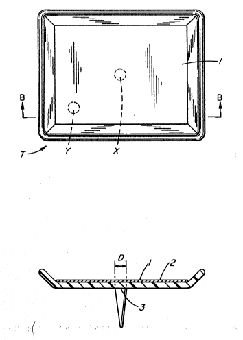
Figure lA is a top plan view of a
surface-patterned article (tray) employed in the
Examples to be discussed below; and ~-
Figure lB is a cross-sectional side elevation
view of the surface-patterned vessel (tray) shown in
Figure lA as taken along line B-B therein. ~ ~
, , ~:
DETAILED DESCRIPTION OF T~E PREFERRED
EXEMPLARY EMBODIMENTS
According to the present invention, a film
consisting essentially of a polybutylene
terephthalate resin and having a pictorial pattern
formed thereon is first placed in a cavity of a ~ -
mold. As is well-known, polybutylene terephthalate
resin is typically obtained by condensing
1,4-butanediol with terephthalic acid or an
ester-forming derivative thereof. Other resins
which are formed mainly of polybutylene
terephthalate units may also be used to form the
printed film used in accordance with the present
inver.tion. For example, copolymers comprised of
butyl!ene terephthalate units as their main
structural units, or modified products obtained by
grafting or crosslinking can be used as the base
resin of the film used in the present invention. ;
.
, ... ..
2 ~
Known additives typically employed in
thermoplastic resins, for example, stabilizers such
as antioxidants and ultraviolet absorbers,
plasticizers, antistatic agents, surface active ;~
agents, crystallization promoters, inorganic
fillers, and other thermoplastic resins, can be `~
biended with the PBT resin depending upon the
properties that are desired. When these additives
are used, consideration must be given to the ;
additive types and amounts so that the intended
effect of the present invention is not diminished.
Incorporation of an additive that either degrades
the transparency of the film (i.e., colors) and/or -
inhibits the film's adhesion to the substrate body
of injection-molded resin must especially be avoided.
The film used in the present invention is
preferably a so-called "back-printed" transparent
film. That is, the film used is one where the
desired pattern is reverse-printed on the film's
back surface so that the intended pattern is visibly
perceptible when the film is observed from the
film's front surface (i.e., through the film's
thickness).
:~ '
The pattern-printed film may be placed in the
mold cavity using electrostatic charging or vacuum
technigues. In the ormer technique, the film is
electrostatically charged opposite to the mold so
that strong electrostatic attraction forces will
assist in the placement of the film in the mold
cavity. In the latter technique, a vacuum is drawn
between the film and the mold to cause the film to
:: .
`
2a~
be drawn into conformance with the mold surface. By
these techniques, reliable placement of the film
within the mold cavity is assured.
'~ :
The thickness of the film is not particularly~ -
critical. However, if the thickness of the film is
too small, there is a risk that the film will break ;
or wrinkle when the molten resin is injected into
the mold cavity. On the other hand, if the
, .:
thickness of the film is too large, the film loses
its transparency thereby degrading the sharpness of
the back-printed pattern. Accordingly, it is ~ '
preferred that the thickness of the film be between
30 to 150 ~m, especially between 50 to lOO ~m.
The temperature of the mold at which the film
is placed is likewise not particularly critical.
However, in order to produce excellent adhesion
between the film and the injected resin, it is
preerred that the mold temperature be between 50 to
150C, especially between 50 to 100C.
,:
With the film properly placed in the mold
cavity (i.e., at a position corresponding to that
portion of the resulting injection-molded article's
surface intended to bear the pattern film), the
molten PBT resin is then injected into the mold
cavity so as to fill~ the same. The patterned film~ !
is thus bonded and integrated to the injected resin
by the heat energy and pressure of the injection
molding process. As noted above, the injection - --;
molded resin is composed mainly of polybutylene ; ~
20~27~
terephthalate and preferably is similar to the resin
that forms the back-printed film.
Materials typically added to ordinary ~
thermoplastic resins can also be incorporated into ~ - -
the PBT resin forming the substrate body. Examples ~ .
of such additives include those mentioned above with ~ ~;
respect to the patterned film, as well as flame
retardants, flame retardant assistants, pigments and
ibrous, plate-shaped or powdery fillers ~uch as
glass fibers, carbon fibers, glass flakes, mica
powder, glass beads or talc powder.
Conditions ordinarily adopted for the injection
molding of polybutylene terephthalate resins, such
as the temperatures of the mold and resin, the
injection pressure, and/or the injection speed can
be adopted as the the conditions used for
injection-molding the molten PBT resin into the
film-lined mold cavity according to the present
invention. It has been found that, in order to
improve the adhesion between the printed film and
the substrate body, it is preferred that the resin
temperature be elevated, and that the injection
speed be lowered. However, if the resin temperature
is too high, resin decomposition and/or film
deterioration ensues. In view of the foregoing, it
is prefèrred thait the rèsin temperature be between ! '
20-60C (preferably between 25-SO~C) greater than
the melting point of the base resin constituting the -i
film. In this way, the greater temperature of the
injection molded PBT resin will cause the film in `;~
the mold cavity to at least partially plasticize ~
.
' ':
, ~
.2~
8 ~
~.
(melt) thereby forming an integral bond with the
injection-molded PBT substitute body. If the
injection speed i5 too low, the resin's moldability
is drastically degraded. In view of the balance
between the adhesion and moldability, it is thus
preferred that the injection speed be between O.S to
3:0 m/min, especially between 1.0 to 2.0 m/min.
It has also been found that the size and
position of the gate influences the finished state
(e.g. film tearing and/or wrinkling~ of the
surface-patterned molded article having a pictorial
pattern formed thereon. From this viewpoint, it is
preferred that a single-point gate be used and that
the gate be disposed on a side of the mold opposite
to the film and in confronting relationship
generally at the film's center. -
The size of the gate depends on the size of the ~-
molded article and the size of the film that forms
the pattern. In this regard, it is preferred that
the cross-sectional area of the gate be between 1.5
to 300 mm2, especially between 7 to 200 mm2. The
geometric shape of the gate is not particularly
critical. Thus, circular, ellipsoidal, square and -
rectangular gate shapes can be appropriately adopted
according to the shape of the molded article and/or
the shape ofithe pattern-printed film. ,If the
pattern-printed film is relatively long and narrow,
a special gate such as a film gate can be adopted.
Furthermore, in the case where a number of films are
used to impart desired patterns to a single molded ~;
. - -
~: ,
2 7 5 ::
article, it is preferred that a respective gate beprovided for each printed film used.
The surface-patterned injection-molded
polybutylene terephthalate resin article which is
prepared according to the above-mentioned process
exhibits good adhesion between the film and the PBT
resin substrate body as well as a good surface
appearance.
Moreover, the surface-printed injection-molded
article of polybutylene terephthalate of the
invention exhibits excellent resistance to heat and
hot water, as well as improved strength and rigidity
properties not possessed by conventional
foil-decorated molded articles. Accordingly, new
end uses of foil-decorated molded articles can be
developed due to the present invention. The molded
articles of the present invention are further
characterized in that no odor migration between the
food and the molded article occurs. Therefore, the
molded articles of the present invention may be
suitably used as tableware, food vessels, or food
trays.
,.
EXA~LES ' ;~: '
,The present inventi`on will`now be described in
detail with reference to the following non-limiting
~ Examples. ; ~-
: :
In the following Examples, film adhesion was
evaluated by the following square-cut peeling test ~
~' .
' 2 ~ 7 6
(according to JIS K-5400). In this regard, square
cuts were formed at intervals of 2 mm between a
region close to the gate (i.e., region X in Figure
lA) and a region distant from the gate (i.e., region
Y in Figure lA). A tape was then applied to the
film and peeled away. Film a&esion was evaluated
based on the number of film squares that were
removed, with the result being expressed by the
number of removed squares per 100 squares).
~ .
ExamPles 1 throuah 7
Molded articles in the form of a tray T (250 mm
x 200 mm x 3 mm) having a pictorial pattern film 1
integrally bonded on an inner surface of the tray's
flat portion 2 as shown in Figures lA and lB were
prepared under various molding conditions specified -
in Table 1. A polybutylene terephthalate film
(having a thickness of 70 or 40 ~m and a melting
point of 228C) back-printed with a pictorial
pattern was used as the pattern film 1 for imparting ~
a pictorial pattern to tray T, while a polybutylene ~ -
terephthalate resin was used as the resin to be
injection molded to form the tray T. The results of
evaluations for these molded articles are shown in
Table 1. ;~
'''~ ' "
'
11 202~7~ ~
~ ,,, . I -- IC ~:
O I O I u~ O I :J Q ~ Q I` I O O ~
~ ~` 1`D 1- 3~ ` 1 ~ o _ I o~ l ~ ~
. . _ 5 _ -O O :
U7 1 o I U7 1 ~ O ~J o O O C~ o o
. ~n I ~ I ~ I ~ t~ O _ O _ _ _ . . :
i 3 e __ _ o
~ ~ o o-lo ~ o lo c ~ ~
~ ~ j _ ~ _ lo o '' ~;;
. O I o I ~ I ~ o O ~ O ~ r- O
x j 1~. 1 ~I I c IJI ~ . ~O j
~1 o i o l ~ 3 1tl O ~J Q O Q ~ O--00
. l~ l u7 l l ~ o o - -
:~ i~ i~ i c ;;~ ~ o~ ~ ~:
l;; - - - - -
~ O I o I u~ ~ ~'1 I 1 1 5 1 1 1 1 . ~ ~ .
~ ~ l ~ 1 ' 1 ~ 1 1` 1` ~ ~l l l j ~ I
~~ 1~0 jO jU jQ 1 1 1 I~ 10 10 1 1
~1 r~- I e
; !5
, j ' ! ~ I e - C ~ c ¦ a
' I o I ~ c j ~ 1 0 1 ~ I c 1 ~ I ~ I c I
I c I ~, I ~.
1 ~ 1 ,
1 '~ I v
2~2~7~
12
Notes For Table 1:
*1: sharpness of the pictorial
pattern and warping or wrinkling of
the film were collectively checked
and appearance was qualitatively
evaluated by a 10-point method where ~ ,
10 is the best and 1 is the worst.
*2: appearance after heating at
100C for 1 hour (the surface state ;
and adhesion of the film) was checked
and gualitatively evaluated by the
10-point method noted above.
*3: appearance after hot water
treatment at 95C for 1 hour (i.e.
surface state and adhesion of the -
film) was checked and qualitatively
evaluated by the 10-point method
noted above.
: '
*4: size at the intersection of the
- tray ~i.e., the location identified ~ `
by reference numeral 3 in Figure 1).
In each Example, a single-point gate
having a circular cross-sectional ~;~
shape and diameter D was disposed at ; ia
a point confronting the center of the
film.
;~ -
, ~ :
E~am~le 8 and ComDarative ExamDle 1 '~
In order to examine odor migration that may ~;
occur in the case of tableware, food vessels or the
like, a cylindrical vessel having a diameter of 100
mm, a depth of 50 mmi and a thickness of 2 mm wlas
molded using either a polybutylene terephthalate -~
resin (Example 8) or a polypropylene resin
(Comparative Example 1). The vessels were filled
with water or oil and heated at 95C. In the case
of the vessel composed of the polybutylene
terephthalate resin, odor migration was not
~ v
~ r~
~2~27B
13 : :
terephthalate resin, odor migration was not
detected. In the case of the vessel composed o~ the
polypropylene resin, an olefin odor was recognized
in the vessel's contents.
While the invention has been described in
connection with what i8 presently considered to be
the most practical and preferrëd embodiment, it is
to be understood that the invention is not to be
limited to the disclosed embodiment, but on the
contrary, is intended to cover various modifications
and equivalent arrangements included within the ;~
spirit and scope of the appended claims.
.~
, . .
.
~ ~ .
: