Note: Descriptions are shown in the official language in which they were submitted.
2020421
HOUSING SEAL CHAMBER BODY
This invention relates to a seal chamber housing
for a pump shaft and including structure for
substantially closing the inner end of the seal chamber
against the movement of pumped fluid thereinto. The seal
chamber additionally includes structure which provides
for additional cha~ber volume about co-actinq stationary
and rotating seal components in the outer end o~ the
chamber, venting and draining of the seal chamber,
flushing of the seal chamber as required, air cooling of
the seal chamber body and/or liquid cooling (or heating)
of the seal chamber body about the seal chamber, and
provisions for monitoring operating temperatures of the
cha~ber housing, all of which features are provided to
extend the operating life of the stationary and rotary
seal components in the outer portion of the seal chamber
under various operating conditions.
Various different forms of cooling arrangements,
labyrinth fluid seals and forced air cooling of seal
chamber bodies heretofore have been provided such as
those disclosed in U.SilPatent Nos. 1,873,267, 2,824,759,
2,846,245, 4,471,963 ~ 4,531,746.~ 1~ However, these
fl~S 15~ l5l~2
previously known st~uctures do not include the
combination of structural and operational features of the
instant invention.
The seal chamber housing of the instant
invention includes a central opening therethrough for
receiving a rotary pump shaft and the opening includes an
inner end portion, an outer end portion and an optional
intermediate length mid-portion disposed between the
.. ~ ~ . - . - .
202~421
inner and outer end portions. The inner portion tapers
outwardly and terminates outwardly in an optional
radially, inwardly projecting annular shoulder and the
mid-portion also tapers outwardly from adjacent the inner
periphery of the shoulder and the outer end portion
tapers outwardly from the termination of the mid-portion
and at a greater angle than the taper of the mid-portion
and/or the inner end portion.
An optional tapered annular bushing may be
seated within the inner end portion of the opening and
the inner periphery thereof may define a labyrinth seal.
The more greatly tapered outer end portion of the opening
and the adjacent end of the mid-portion of the opening
are adapted to receive co-acting stationary and rotary
seals therein and the chamber has vent and drain ports
opening thereinto at the major diameter end of the
mid-portion of the opening and flushing ports opening
thereinto at the minor diameter end of the mid-portion of
the opening in outwardly inclined directions. Also, a
liquid cooling channel extends about outer side of the
chamber body about the inner end portion and mid-portion
of the opening and air cooli~g structure i8 provided on
the outer side of the chamber body outwardly of the
aforementioned channel.
The main object of this invention is to provide
a seal chamber for containing co-acting stationary and
rotary seal components and designed to greatly extend the
operation life of the stationary and rotary seal
components.
A further object of this invention is to provide
a seal chamber designed specifically to provide
appreciably greater chamber volume about the stationary
and rotary seal components therein for more effective
cooling and cleaning of the seal components.
' ' .. '
,
'~
,
. :
2020421
Another object of this invention is to provide
a seal chamber housing including external air cooling
structure for atmospheric cooling of the chamber housing
for applications not requiring the more intensive cooling
provided by an external fluid cooling system.
Still another important object of this invention
is to provide a seal chamber housing incorporating an
external fluid cooling (or heating) channel therein for
external fluid cooling (or heating) of the chamber body
for applications requiring enhanced cooling or
applications requiring heating of the housing and
enclosed chamber contents.
Yet another ob;ect of this invention is to
provide a seal chamber including structure designed to
greatly facilitate flushing of the seal chamber in an
area thereof disposed about the stationary and rotary
seal components.
Another object of this invention is to provide
an optional bushing for substantially closing the inner
end of the tapered seal chamber against the entrance of
a pumped fluid therein and/or against the loss of seal
flush liguid from within the chamber volume.
Another important object of this invention is to
provide a seal chamber which may be readily vented and
drained when the optional bushing is utilized.
A final object of this invention to be
specifically enumerated herein is to provide a seal
chamber housing in accordance with the preceding objects
and ~which will conform to co m entional forms of
manufacture, be of simple construction and dependable in
operation 80 as to provide a device that will be
economically feasible, long-lasting and relatively
trouble free.
.. . .
, . ~ . . - .
.; . . - .. - .
- . ~ ..
- , .~- . . ..
2020~21
These, together with other ob;ects and
advantages which will become subsequently apparent,
reside in the details of construction and operation as
more fully hereinafter described and claimed, reference
being had to the accompanying drawings forming a part
hereof, wherein like numerals refer to like parts
throughout.
Figure 1 is a front elevational view of the
preferred form of the seal chamber housing of the instant
invention as seen from the outer side thereof;
Figure 2 is an enlarged fragmentary vertical
sectional view taking substantially upon the plane
indicated by the section line 2-2 of Figure 1: and
Figure 3 is a further enlarged fragmentary
horizontal sectional view taking substantially upon the
plane indicated by the section line 3-3 of Figure 1.
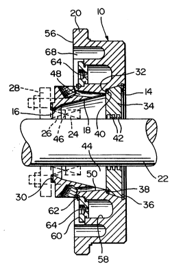
Referring now more specifically to the drawings
the numeral 10 generally designates the seal chamber
housing of the instant invention.
The body 10 is annular in configuration and
defines a central opening 12 extending therethrough
including inner and outer end portions 14 and 16 and an
intermediate length mid-portion 18.
The outer periphery of the body 10 defines an
abutment flange 20 for abutting against and sealed
engagement with a pump body casing and the opening 12
receives an associated pump shaft 22 therethrough.
Co-acting rotating and stationary ~eal components 24 and
26 are to be used in forming a seal between the shaft 22
and a gland 28 removable secured to the outer side of the
body 10 against an annular gasket 30 disposed between the
gland 28 and the body 10.
.- :
.. ... . .
'` :- '' . ,
2020421
The inner end portion 14 is outwardly tapered and
terminates outwardly at a radially, inwardly projecting
abutment shoulder 32 and the mid-length portion 18 also
outwardly tapers at substantially the same angle as the
inner end portion 14.
An optional tapered bushing 34 may be removably
seated within the inner end portion 14 through the
utilization of a snap ring 36 and the outer periphery of
the minor diameter end of the bushing 34 includes a
rabbet 38 in which an O-ring 40 is received forming a
fluid tight seal between the bushing 34 and the inner end
portion 14 of the opening 10. The seating of the bushing
34 within the outer end portion 14 of the opening 12
enables the O-ring seal 40 to form a proper seal without
any chance of the O-ring seal 40 being over compressed.
The inner periphery of the annular bushing 34 may
be provided with labyrinth grooves 42 which are operative
to substantially block the seal chamber 44 defined by the
outer end portion and the mid-portion of the opening 12
; against the entrance of pumped fluid therein and/or
against logs of geal flush liquid from within.
The greater taper of the outer end portion 16 of
the opening 12 provides for considerably greater chamber
volume extending about the interface 46 between the seal
components 24 and 26 thereby enabling greater cooling
thereof by fluid within the chamber 44.
Upper and lower vent and drain ports 48 and 50
open into the major diameter end portion of the
mid-portion 44 of the opening 16 at the upper and lower
peripheries, respectively, thereof and may be utilized to
drain and/or vent fluids from the chamber 44. The outer
portions of the ports 48 and 50 include pipe thread
equipped counterbores whereby the ports 48 and 50 may be
plugged or have threaded pipe fittings operatively
- . . -. :
".
' - ' . : ~ ' . :
2020421
engaged therein.
In addition, circulation ports 52 and 54 open
into the minor diameter end portion of the mid-portion 18
of the opening 12 in a direction inclined toward the
outer end`portion 16 of the opening 12 to provide a
spiral flow of flush liquid around interface 46 for
optimum cooling, cleaning, and lubricating of seal
components 24 and 26. The ports 52 and 54 also include
pipe thread equipped outer end large counterbores.
Suitable flushing liquids may be pumped into the chamber
44 via either (or both~ of the ports 52 and 54.
It will be noted from Fig. 1 of the drawings
that the pipe-threaded counterbores of ports 52 and 54
are disposed upon a chord of the opening 12. Further,
the body 10 may also be mounted in a 180 angularly
displaced position such that the ports so and 48 are
disposed uppermost and lowermost, respectively, and the
ports 52 and 54 will be disposed above the center axis of
the opening 12 as opposed to below the center axis of the
opening 12. This unique placement of ports 48, 50, 52,
and 54 provides for improved accessibility to ports 52
and 54 when required.
The outer side 56 of the body 10 includes an
annular outwardly opening cooling channel 58 formed
therein and the outer extrememity of the cooling channel
58 is removably closed by a double 0-ring equipped
annular closure plate 60 removably secured over the open
outer side of the cooling channel 58 by the utilization
of a snap ring 62. The closure plate 60 includes fluid
circulation ports 64 formed therethrough by which cooling
(or heating) fluid may be caused to flow through the
chamber 58. Further, from a comparison of Figs. 1 and 2,
it may be seen that the outer side 56 of the body 10 is
provided with circumferentially spaced outer periphery
..~ .. - .. ...
. .; .
2020421
air cooling recesses 68.
Because the mid-portion 18 of the opening 12 is
tapered outwardly at a shallow angle and the outer end
portion 16 is tapered outwardly at a sharper angle than
the taper of the mid-portion or inner end portion,
appreciably more volume of the chamber 44 is disposed
about the plane of the interface 46 between the seal
components 24 and 26. Thus, a greater flushing action of
the seal interface area and cooling action thereon is
enabled.
The diametrically opposite ports 48 and 50 may
be used for venting and draining the chamber 44, when
desired and the ports 52 and 54 may be used for flushing
the chamber 44 and, in particular, the area of the
chamber 44 which is disposed in the plane of the
interface 46 between the seal components 24 and 26.
Still further, fluid cooling of the body 10 immediately
about the chamber 44 may be effected by passing cooling
fluid through the ports 64 and the chamber 58, or such
fluid may be used for heating purposes, if desired.
Also, the recesses 68 provide for ambient air cooling of
the outer periphery of the body 10.
: It is also pointed out that the stepped conical
opening 12, and particularly the mid-portion 18 and outer
end portion 16 thereof, supports a discontinuous
vortexing action of the liquid within the chamber 44 to
promote cooling and to provide for removal or reduction
of solids or debris from around the plane of the
interface 46 of the seal components 24 and 26. These
solids may then be drained via port 50 (or 48) when the
optional bushing 34 is in place. When optional bushing
34 i~ not inserted, this said vortexing action is
continued and completed along the inner end portion 14
thus removing solids or debris into the pumping mechanism
: .:
2020421
for removal from the pump via the pump dischar~e.
A chamber having a single surface with, for
example, a constant taper would generally form a
continuous vortex resulting in higher fluid velocities
causing abrasive particles in the fluid to spin at these
higher velocities against the OD wall of the chamber
causing premature wear. In addition, one continuous
vortex would generally create a higher vacuum situation
at the vortex center resulting in poor lubrication and
dry running of the seal faces because of the naturally
occurring pressure depression at the center.
The present invention with stepped surfaces and
changing tapers, on the other hand, results in a
discontinuous vortex or multiple vortices which force the
entrained particles away from the seal faces to the outer
wall of the chamber, but at lower velocities resulting in
less wear.
In addition, a discontinuous vortex or multiple
vortices result in a less intense vacuum situation in the
vicinity of the seal faces reducing the possibility of
dry running.
Also, as previously herein before set forth, the
stepped conical opening 12 insures maximum liquid volume
around the mating faces of the seal components 24 and 26,
thus providing a proper heat sink for cooling of the
mechanical seal faces and the provision of the chamber 58
and the cover plate 60 enable positive and precisely
controlled cooling (or heating) of the area of the body
10 defining chamber 44.
The foregoing is considered as illustrative only
of the principles of the invention. Further, since
numerous modifications and changes will readily occur to
those skilled in the art, it is not desired to limit the
invention to the exact construction and operation shown
- . . -. .
.
:' ~`' . .
,
2020~21
and described, and accordingly, all suitable
modifications and equivalents may be resorted to, falling
within the scope of the invention.
.
:.
- : -
- ~ .
.
- , ~ . . -