Note: Descriptions are shown in the official language in which they were submitted.
2~2~626
- The present invention relates to a radio tele-
communication apparatus mounted on a mobile body such as an
automobile.
An automobile radio communication apparatus is available
as one of means for constituting a communication network
including a mobile body.
Recently, such a radio communication apparatus has been
rapidly spread and has become popular. However, the charge
rate of this apparatus is considerably higher than that of a
normal wire telephone. For this reason, a demand has arisen
for means for managing the call charge of a radio telephone
during speech communication and preventing wasteful, long
speech communication.
The present invention provides a radio telecommunication
apparatus which can inform a user that a call charge for one
call exceeds a preset call charge.
The present invention also provides a radio
telecommunication apparatus which can stop speech
communication when a call charge for one call exceeds a
preset call charge.
Further, the present invention provides a radio
telecommunication apparatus which can inform a user that
accumulated call charges exceed a preset call charge.
Still further, the present invention provides a radio
telecommunication apparatus which can stop speech
communication when accumulated call charges exceed a preset
call ch~rge.
-- 1 --
A
,
.
-
,. ~ .
. .
- . ,.
2~20626
According to one aspect, the invention provides a radio
telecommunication apparatus, comprising:
means for making a telecommunication link between the
user of said apparatus and a second party to make a call for
S speech communication therebetween; means for obtaining a
charge rate from s~stem data from a base station coupled to
said apparatus; means coupled to said obtaining means for
storing the charge rate; means for setting a first allowable
call charge for one call; means, coupled to said setting
means, for storing the first allowable call charge; means,
coupled to said making means, for counting the time used for
speech communication time in the call and providing a count
value corresponding thereto; means, coupled to said charge
rate storing means and said counting means, for calculating a
current call charge based on said charge rate and said count
value; means, coupled to said calculating means and said
first allowable call charge storing means, for comparing said
current call charge with the first allowable call charge to
determine whether the current call charge exceeds the first
allowable call charge; and means, coupled to said comparing
means, for informing both the user of the apparatus and the
second party when the current call charge exceeds the first
allowable call charge.
According to a further aspect, the invention provides a
radio telecommunication apparatus, comprising:
means for making a telecommunication link between the
u~er o~ said apparatus and a second party to make a call for
speech communication therebetween; means for setting a charge
xate and a first allowable call charge for each call; means
coupled to said setting means, for storing the charge rate;
means coupled to said setting means for storing the first
allowable call charge; means, coupled to said making means,
-- 2 --
'
,
.. . . .
.
' . .;
~2~6~6
for counting the time used for speech communication for the
call and providing a count value corresponding thereto;
means, coupled to said charge rate storing means and said
counting means, for calculating a current call charge based
on said charge rate and said count value;
means, coupled to said calculating means and said first
allowable call charge storing means, for comparing said
current call charge with the first allowable call charge to
determined whether the current call charge exceeds the first
allowable call charge; and means, coupled to said comparing
means, for informing both the user of the apparatus and the
second party when the current call charge exceeds the first
allowable call charge.
lS In a preferred embodiment of the above aspects, the
invention provides:
The above apparatus, wherein said setting means includes
means for setting a second allowable call charge for a
plurality of calls, said first allowable call charge storing
means includes means for storing the second allowable call
charge and means, coupled to said calculating means, for
sequentially storing an accumulated call charge calculated by
said calculating means for previously made calls, said
comparing means is further coupled to the accumulated call
charge storing means, and includes means for comparing said
accumulated call charge with the second allowable call charge
to determine whether the accumulated call charge exceeds the
second allowable call charge, and said informing means
informs both the user of the apparatus and the second party
when the accumulated call charge exceeds the second allowable
call charge.
- 3 -
..
', : "
. . .
.
2~2~6~6
According to a still further aspect, the invention
provides a radio telecommunication apparatus, comprising:
means for detecting a signal representing a charge rate
transmitted over a radio channel; means coupled to said
detecting means for storing said signal representing a charge
rate; means for making a telecoD unication link between the
user of said apparatus and a second party over one or more
radio channels; means coupled to said making means for
measuring an elapsed time from the time of making the
telecommunication link; means, coupled to said signal storing
means and said time measuring means, for calculating a
telecommunication charge based on said charge rate and said
elapsed time; and means, coupled to said calculating means,
for alarming both the user of the apparatus and the second
party when said telecommunication charge exceeds a first
predetermined criterion.
In preferred embodiments of this aspect, the invention
provides:
The above apparatus, further comprising means, coupled
to said calculating means, for breaking said
telecommunication link when the telecommunication charge
exceeds a second predetermined criterion.
The immediately above apparatus, further comprising
mean~ for setting the apparatus in a registration mode, and
input means, coupled to said alarming means and said
telecommunication link breaking means, for inputting the
fir~t and ~econd predetermined criteria when the apparatus is
in the registration mode, wherein the first and second
criteria repre~ent allowable call charges.
- 4 -
,~ .
.. ..
, ~: .
2~20626
The above apparatus, wherein said making means includes
means for making the telecommunication link in response to a
call request from the user of the apparatus.
The above apparatus, wherein said calculating means
includes means for multiplying the elapsed time with the
charge rate.
The above apparatus, further comprising means, coupled
to said calculating means, for storing data representative of
an accumulated telecommunication charge which is updated each
time the telecommunication link is broken; and wherein said
data storing means includes a non-volatile memory.
The immediateIy above apparatus, wherein said alarming
means includes means for alarming both the user of the
apparatus and the second party when said data exceeds a third
predetermined criterion.
The invention also provides a radio telecommunication
apparatu~, comprising:
means for detecting a signal representing a charge rate
transmitted over a radio channel; means coupled to said
detecting means for storing said signal representing a charge
rate; means for making a telecommunication link between the
user of said apparatus and a second party over one or more
radio channels; means coupled to said making means for
measuring an elapsed time from the time of making the
telecommunication link; means coupled to said signal storing
means and said time measuring means for calculating a
telecommunication charge based on said charge rate and said
elap~ed tlmes means coupled to said calculating means for
- 4a -
- '
2~2~62~
indicating the telecommunication charge to the user of the
apparatus; and means coupled to said calculating means for
alarming both the user of the apparatus and the second party
when the telecommunication charge exceeds a first
predetermined criterion.
This invention can be more fully understood from the
following detailed description when taken in conjunction with
the accompanying drawings, in which:
Fig. 1 is a block diagram for explaining an arrangement
of an overall radio telecommunication apparatus according to
the present invention;
Fig. 2 is a block diagram showing a radio unit in the
radio telecommunication apparatus in Fig. 1;
~, ,
.. . .....
. : ": . '
~ "~
2~2~7~
-- 5 --
Fig. 3 is a flow chart showing an operation
sequence of a radio telecommunication apparatus accord-
ing to the first embodiment of the present invention;
Fig. 4 is a flow chart showing an operation
sequence of a radio telecommunication apparatus accord-
ing to the second embodiment of the present invention;
Fig. 5 is a flow chart showing an operation
sequence of a radio telecommunication apparatus accord-
lng to the third embodiment of the present invention;
and
Fig. 6 is a flow chart showing an operation
sequence of a radio telecommunication apparatus accord-
ing to the fourth embodiment of the present invention.
A preferred embodiment of the present invention
lS applied in a mobile telephone will be described with
reference to the accompanying drawings.
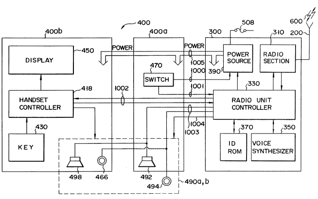
Fig. 1 is a block diagram showing an arrangement of
a moblle telephone apparatus according to an embodiment
of the present invention. Referring to Fig. 1, mobile
telephone apparatus 100 comprlses antenna 200, radio
unit 300 and telephone unit 400. Antenna 200 is mounted
on an outer body surface of an automobile. Telephone
unit 400 is mounted near the drlver's seat lnside the
automoblle.
Radio unit 300 includes radlo section 310 for
establlshlng radlo channels 600 wlth a base station (not
shown) through antenna 200 and for exchanglng signals
. .
2~2~ 6
therewith, radio unit controller 330 for controlling the
overall operations of the apparatus, voice synthesis
circuit 350 for synthesizing voices, ID ROM 370 for
storing ID numbers with the corresponding system iden-
tification numbers and power source 390 for supplying
power from the battery mounted in the automobile to the
above components through fuse 508.
Telephone unit 400 includes handset controller 418
for controlling the overall operations of telephone unit
400 in response to instructions or the like from radio
unit controller 330, key unlt 430 for entering key
inputs, display unit 450 for displaying numerical or
alphabetical characters in response to control signals
from handset controller 418, switches 470 including a
hook switch and a power switch, and selectable audio
input/output units 490a and 490b for inputting or
outputting an audible sound. Telephone unit 400 may
be divided into main unit 400a and handset 400b. Micro-
phone 494 may be a hands-free microphone 494 mounted on
a sun visor or the like near the driver's seat and is
connected to maln unlt 400a. Loudspeaker 492 may be
mounted ln main unit 400a. Handset controller 418, key
unit 430, and dlsplay unit 450 are mounted ln handset
400b. Handset mlcrophone 466 and handset recelver 498
constltute audlo lnput/output unlt 490b of handset 400b.
Each sectlon of radlo unlt 300, maln unlt 400a and
handset 400b are supplled wlth power by way of a power
' :
.
.~
' ', ,.
2~2~
-- 7 --
line 1005 extending from power source 390 in radio unit
300. The opened or closed status of switches 470 is
transmitted to power source 390 or radio unit controller
330 by way of line 1000 or line 1001, respectively.
Control and/or command signals are transmitted between
handset controller 418 and radio unit controller 330 by
way of line 1002. Audio signals are transmitted by way
of lines 1003. Radio unit controller 330 sends control
signals to audio input/output unit 490a, 490b by way of
lines 1004.
Fig. 2 is a block diagram showing a detailed
arrangement of the radio unit of Fig. 1. Referring
to Fig. 2, radio section 310 comprises demodulator
312, modulator 314, duplexer 318 and synthesizer 320.
Demodulator 312 demodulates a radio signal received
from the base station through radio channels 600,
antenna 200 and duplexer 318. It should be noted that
this signal includes audible sound signals and control
signals. Modulator 314 modulates the audio and control
signals received from audio controller 300 and generates
the requlred transmi~sion slgnals.
Power ampllfler 316 ampllfles the transmlssion
slgnals received from modulator 314. The ampllfication
of power ampllfler 316 may be continuous or variable in
a step-wlse fashlon, e.g., 8-step varlable. Duplexer
318 sends the signals received through radio channel 600
to demodulator 312 and the signals from modulator 314
,
.
2~2a~ ~ ~
-- 8 --
and power amplifier 316 to antenna 200. Synthesizer 320
is formed of a channel selection local oscillator and
specifies a frequency from which signals are demodulated
by demodulator 312 and a frequency to which signals are
modulated by modulator 314.
Radio unit controller 330 is formed at central
processing unit (CPU) 331, oscillator/frequency divider
332, address decoder 333, ROM 334, RAM 335, radio
controller 336, audio circuit 337, control slgnal
processor 338, audio circuit controller 339, digital
interface 340, power controller 341 and interrupt
controller 342. Reference numerals 343, 344 and 345
denote a data bus, an address bus and a control bus,
respectively. CPU 331 controls the operatlon of radio
unlt controller 330. Osclllator/frequency dlvider 332
supplles clock slgnals to CPU 331 and dlvldes the clock
slgnals to supply approprlate frequency-dlvlded pulses
as tlmlng pulses to each sectlon of the moblle telephone
apparatus requlrlng them. Address decoder 333 outputs
predetermlned operation slgnals to the components ln
response to instruction slgnals from CPU 331. ROM 334
stores varlous programs requlred for operation of CPU
331. RAM 335 stores varlous types of data durlng
processing for use by CPU 331. Radio controller 336
controls radio section 310 in response to lnstructions
from CPU 331. For example, radlo controller 336
sends signals lndlcatlve of avallable frequencles to
;
2 ~ 2 ~
synthesizer 320, sl gnals indicative of an amplificatlon
level to power amplifier 316, and signals indicative
of modulation parameters to modulator 314. Radio
controller 336 receives a step-out signal from synthe-
sizer 320 and output power detection signals from poweramplifier 316 and forwards these signals to CPU 331,
thereby preventing operational errors.
Audio circuit 337 extracts control signals and
audio signals from the received signals demodulated by
demodulator 312 and supplies the control signals to
control signal processor 338 and the audio signals to
telephone unit 400. Audio circuit 337 also supplies
a control signal from control signal processor 338 and
audio signals from telephone set 400 to modulator 314.
It should be noted that audio circult 337 also arranges
the waveform of the control signal to be sent to control
slgnal processor 338 in a particular slgnal format and
filters the control signal to be supplied to modulator
314. Control signal processor 338 acquires bit and
frame synchronization with the control signal from audio
circult 337. Malntainlng the requlred synchronlzation,
control signal processor 338 converts the serial control
slgnals, lncludlng control data recelved from a base
statlon, lnto parallel slgnals and converts the parallel
control data slgnals to be transmltted to a base station
lnto serlal signals. The control signals are set to and
from the base statlon vla audlo clrcuit 337.
202~2i'3
-- 10 --
Audio circuit controller 339 controls audio circuit
337. Under the control of audio circuit controller 339,
for example, audio circuit 337 applies the received
signals from demodulator 312 to control signal processor
338 or telephone unit 400 and selectively receives the
signals from control signal processor 338 or telephone
unit 400. Digital interface 340 interfaces the data
communication between radio unit 300 and telephone unit
400. Power controller 341 controls power source 390
and sets a voltage supplied from battery 506 to power
source 390 to a predetermined level. The voltage having
the predetermined level is supplied to the respective
clrcult components.
An operation of the radlo telecommunlcatlon appa-
ratus havlng the above-described arrangement accordlng
to the flrst embodlment of the present lnventlon wlll be
descrlbed below.
Prlor to speech communlcatlon processing in the
apparatus of thls embodlment, the apparatus may be
swltched from a standby state to an allowable call
charge reglstratlon mode by a predetermlned key opera-
tlons, e.g., depresslng keys oflFCN 1, ~ , ~ ,
continuously. After that, an allowable call charge may
be reglstered into the apparatus by operatlng ten-keys.
For example, keys of m ~ ln the key sectlon 430
are operated to enter $10 as the allowable call charge,
and thls lnput value ls stored ln the ID ROM 370
. ........ . . .
, ~' ' ' ,
2~ ,3
-- 11 --
constituted by an E2PROM.
The flow of operation shifts to an outgoing call
operation in response to the input of a destination
telephone number and the send key. Upon this outgoing
call operation, over a control channel established
between the apparatus and the base station, system data
is received from the base station. Information repre-
sentative of a charge rate is then extracted from this
system data and is stored in the RAM 335.
The base station designates a speech channel for
the mobile unit. In accordance with this designation,
the mobile unit is tuned to the speech channel, and the
base statlon ls also tuned to the speech channel.
Speech communication ls then started through the
deslgnated speech channel.
In synchronlsm wlth an establishment of a speech
communlcation llnk, the CPU 331 starts to count a speech
communlcatlon tlme by uslng an lnternal clock pulse,
and sequentlally calculates call charges on the basis of
the charge rate stored in the RAM 335 and the count
values. The CPU 331 fetches the allowable call charge
data from the ROM 370 and compares it with the calcula-
tlon results. If it is determined that a call charge
exceeds the allowable call charge, the CPU 331 sends a
control slgnal for generatlng an alarm slgnal to the
audio clrcuit 337. The audlo clrcult 337 sends the
alarm slgnal to the loudspeaker 492 or the handset
292~52s5
- 12 -
receiver 498 so as to cause the loudspeaker 492 or the
handset receiver 498 to generate an alarm.
The user can confirm from this alarm that the
current call charge exceeds the allowable call charge.
Therefore, the speech communication time can be managed
in accordance with this alarm.
The above-described operation will be described in
more detail below with reference to the flow chart in
Fig. 3.
When it ls determined in step 30 that the
operatlonal state of the apparatus transits from a
standby state to a speech communication state in which
a speech communication link is established, the radio
section 310 of the apparatus receives signals trans-
mitted from the base station over the established speech
communicatlon link. The received signals are applied
to the control signal processor 338 through the audio
clrcult 337. The control slgnal processor 338 detects a
synchronization slgnal, an address data addresslng the
apparatus, and the followlng system data in the received
slgnals. The detected system data are applied to CPU
331 vla bus lines. The system data include lnformation
concernlng a charge rate, whlch ls extracted by CPU 331.
CPU 331 stores the extracted charge rate informatlon
lnto the ~AM 335 ln step 31. The charge rate infor-
matlon, for example, conslsts of ten (10) blts. In step
32, the CPU 331 starts call charge count by startlng to
., . ,: ,
,
202~626
- 13 -
count a speech communication time, thus starting to
calculate a call charge on the basis of the counted time
and the charge rate obtained from the data received from
the base station. More specifically, CPU 331 calculates
a call charge by multiplexing the counted time by the
charge rate. In addition, the calculated call charge
may be displayed on display unit 450 under the control
of CPU 331. Thus, the user may be always informed of
the call charge.
In step 33, the CPU 331 compares the calculated
call charge with a preset allowable call charge which
was stored in the allowable call charge registration
mode so as to check whether the current call charge
exceeds the allowable call charge. If NO in step 33,
the flow advances to step 34, and the CPU 331 calculates
the next call charge corresponding to an incremented
count time. After it is determined in step 35 that the
speech communication link is still established, the flow
returns to step 33 in which the current call charge is
compared with the allowable call charge.
If the CPU 331 determines that the current call
charge exceeds the preset allowable call charge, it
starts, for example, the following processing in step
36:
~1) generatlng an alarm from the loudspeaker 492
or the handset recelver 498 in the mobile unit by
superposing it on speech;
.
20~626
(2) transmitting an alarm signal to the destina-
tion by superposing it on speech signals to be trans-
mitted;
(3) displaying an alarm message on the display
unit 450;
(4) causing a backlight for the display unit 450
to blink.
Note that these operations may be independently or
simultaneously performed.
This lndication processing may be continued until
a speech communication link using the speech channel is
broken down owing to user's on-hook operations and so on
(steps 37 and 38). After that, the apparatus is set
in a standby state again.
According to the radio telecommunication apparatus
of this embodiment, therefore, long speech communication
is determined on the basis of a call charge, and this
lengthy talk can be informed to the user.
In the above-mentioned embodiment, while the charge
rate is obtained through the speech communication llnk
after it ls established, the charge rate may be obtained
in advance through a control channel before the speech
communlcatlon link ls established.
The second embodlment of the present lnventlon will
be descrlbed below wlth reference to the flow chart in
Flg. 4.
When lt ls determlned ln ætep 20 that the apparatus
: ' .
2~2~526
is set from a standby state to a speech communication
state, the CPU 331 receives system data from the base
station, reads a charge rate from the system data, and
stores it in the RAM 335 in step 21. In step 22, the
CPU 331 starts to count a speech communication time so
as to start call charge count, and starts to calculate a
call charge on the basis of the speech communication
time and the charge rate.
In step 23, the CPU 331 compares the calculated
call charge with a preset allowable call charge so as
to check whether the current call charge exceeds the
allowable call charge. If NO in step 23, the flow
advances to step 24 to calculate the next call charge
by uslng the call charge call count. When the CPU 331
determlnes that the speech communlcatlon llnk ls stlll
establlshed, the flow returns to step 23 to compare the
current call charge with the allowable call charge.
If the CPU 331 determines in step 23 that the
current call charge exceeds the preset allowable call
charge, it controls synthesizer 320 so as to supply
demodulator 312 wlth signals having frequencies for
scannlng the control channel and modulator 314 to be
turned off. Consequently, the established speech
communlcatlon llnk ls termlnated ln response to the
excess of the call charge (step 26). After that, the
operatlon returns to the standby state.
Accordlng to the radio telecommunlcatlon apparatus
202~2~
- 16 -
of this embodiment, long speech communication is deter-
mined on the basis of a call charge, and the speech
communication can be forcibly ended. Therefore, a good
economical effect can be expected.
The third embodiment of the present invention will
be described below.
Fig. 5 is a flow chart showing an operation
sequence of the apparatus of the third embodiment.
In this apparatus, indlcation processing is exe-
cuted when an accumulated call charge for a plurality of
calls exceeds a second preset allowable call charge.
The second allowable call charge is stored in the ROM
370 by a key-operation in the same manner as in the
above-descrlbed embodiments. The accumulated call
charge up to the last call is also stored in the ROM
370.
When the apparatus is set from a standby state to
a speech communlcation state, the CPU 331 checks in
step 40 whether the accumulated call charge exceeds the
second preset allowable call charge. If YES in step 40,
predetermlned processing indlcatlon and communlcatlon
control operatlons of, e.g., lnhlbltlng speech communl-
catlon or generatlng an alarm, and lnformlng the user
of thls state is performed ln the slmllar manner as
descrlbed ln the above-mentloned embodlments (step 42).
If NO in step 40, the flow advances to step 41.
After outgolng call processlng, the CPU 331 recelves
202~626
- 17 -
system data from the base station, reads a charge rate
from the system data, and stores it in the RAM 335 in
step 43. In step 44, call charge count is started. A
call charge based on this count result is added to the
previous accumulated call charge stored in the ROM
370, and the updated accumulated call charge is stored
in the RAM 335. In step 45, the CPU 331 compares the
accumulated call charge with the second allowable call
charge. If the accumulated call charge exceeds the
second allowable call charge, the above-described
indlcation and communication control operations is
performed ln step 42.
If the accumulated call charge does not exceed the
second allowable call charge, call charge count is con-
tlnued ln step 46. If it ls determined that the speechradlo llnk ls still establlshed ln step 47, the flow
returns to step 45 to perform the same declslon proc-
esslng as described above.
After the speech communlcatlon llnk ls broken down,
the current accumulated call charge ls wrltten ln the
ROM 370.
Note that the above~descrlbed indlcatlon and
communlcatlon control operatlons can be canceled by
clearlng the accumulated call charge stored ln the ROM
370.
Accordlng to the radlo telecommunlcatlon apparatus
of thls embodlment, whether the accumulated call charge
.,.,, .: ;
. .. .
2~2o626~
exceeds the second allowable call charge can be informed to
the user.
The accumulated call charge may be stored in a
detachable memory device, e.g. an IC card.
The fourth embodiment of the present invention will be
described below with reference to Figs. 1, 2, and 6. In this
embodiment, while the apparatus is in a standby state before
speech communication, a unit time and a charge rate as call
charge units are entered by the key unit 430 and are stored
in the ROM 370 in step 50.
Upon operation of the key unit 430, an allowable call
charge is entered as a call charge limit allowed for one
call, and is stored in the RAM 335 while each input value is
checked on the display unit 450.
When outgoing call processing is performed by enter-
ing a destination telephone number from the key unit 430
in ~tep 51, the radio unit controller 330 performs out-
going call connection processing with respect to the
base station through the mobile antenna 200. Upon
completion of the connection processing, the apparatus is
set in a speech communication state. In this speech
communication state, an audible sound signal received
through the mobile antenna 200 and the radio section
310 is sent to the loudspeaker 492 through the
- 18 -
.~
2020fi~6
-- 19 --
audio circuit 337. The audible sound signal input from
the microphone 466 is sent to the radio section 310
through the audio circuit 337.
In this radio telecommunication apparatus, count of
a speech communication time is started at the same time
when a speech communication state is set, and calcula-
tion of a call charge is started by using the counted
time and the preset charge rate in step 52. In step 53,
the call charges are sequentially compared with the
present allowable call charge with the lapse of a speech
communicatlon time. If it is determined in step 53 that
the current call charge exceeds the allowable call
charge, the flow advances to step 54 to inform this
state to the user. Subsequently, on-hook processing is
performed (step 55), and information processing is ended
~step 56).
If the current call charge does not exceed the
allowable call charge, the flow advances to step 57 to
contlnue call charge count. When it ls determined in
step 58 that the line is still connected, the flow
returns to step 53. This processing is repeated until
the current call charge exceeds the allowable call
charge.
The thlrd embodiment may be comblned wlth the
flrst, second, or fourth embodlment. Wlth such a
combinatlon, an accumulated call charge based on a
plurallty of calls can be slmultaneously managed wlth
,. . . ..
2020~
- 20 -
a call charge based on one call.
Still, any other combinations of the above-
mentioned embodiments fall into the scope of the present
invention. For example, the speech communication link
may be terminated after the user is alarmed. In this
event, a criterion for a disconnection of the speech
communication link is greater than a criterion for an
alarm.