Note: Descriptions are shown in the official language in which they were submitted.
I~lETHOD AND DEVICE FOR ELIPRINATIPJG
THE EFFECT OF PERIODTC DISTURBANCE
VARIABLES HAVING A KNOWN VARIABLE FREQUENCY
BACKGROUND OF THE INVENTION
This invention relates to a method and device for
eliminating the effect of periodic disturbance variables
having a known, variable frequency in general and more
particularly, to a method and device for eliminating the
effect of periodic disturbance variables having a known,
variable frequency affecting control loops between the
controlled system and the final controlling element.
These types of frequency-variable disturbances
l0 originate in the case of driving mechanisms, for
example, from torque ripple factors proportional to
rotational speed and result from design-dependent flux
asymmetries in the machine, or periodic bearing load
content caused by a rotating out-of-balance force in
electromagnetically supported rotors.
German Patent 26 58 692 discloses compensating for
the effect of such an out-of-balance force, in the case
~f a magnetic rotor bearing arrangement, by means of a
_~_
control loop in a transformed coordinate system, which
is fixed relative to the rotor. With this method the
effect of the out-of-balance force in the effective
circuit across the controlled system is eliminated by
the controller. This means that the changes in position
produced by the periodic out-of-balance force must first
pass through the closed loop before they can be
eliminated by the position controller. Only moderately
fast frequency variations in the disturbance variable
can be effectively dealt with using this method.
In view of the prior art, there is a need for a
method and device to eliminate disturbance variables
occurring in control loops with a wider range of
frequency variation.
SUMMARY OF TIE INVENTION
according to the present invention, this task is
accomplished by a method of parallel elimination of
disturbance variables, which is operative without a
feedback-control-effective circ~:it across the controlled
system and with which one is able to react faster,
particularly in the case of frequency variations in the
disturbance variable. More specifically
this method and device eliminate the effects of periodic
disturbance variables having a known, variable
3 -
frequency, affecting control loops between a final
controlling element and a controlled system. This
method consists of obtaining a first signal from a first
splitoff point before a point of application of the
disturbance variable and then obtaining a second signal
at a second splitoff point after the point of_
application of the disturbance variable. Next one feeds
the first and second signals to a mixing element and
then selects a selected signal from the mixing element
which depends solely upon the disturbance variable.
Then using frequency function generators to generate
real and imaginary frequency dependent parts of a
dimensioned complex correction frequency operation in a
correcting element, one amplitude-weights at least a
fundamental wave component of the selected signal and a
signal that is 90° phase leading the selected signal in
the correcting element. Next one sums the amplitude-
weighted fundamental wave component and the phase-
leading signal in the correcting element to obtain a
summed signal and then applies the summed signal either
to compensate for disturbance variables before the first
splitoff point, or to blank out disturbance variables
after the second splitoff point.
In the present invention a signal is selected
which is solely dependent on the disturbance variable
and then the correction signal required for disturbance
feedforward control is formed from the selected signal,
_~_
by means of a complex phaser calculation. An important
advantage which results with the invention is that it
functions completely independently of the control loop
used at the time; that is it can easily be added to
already existing control loops, such that a feedback
control can be dimensioned and established independently
of the disturbance variable elimination according to the
invention.
DRIFF DESC~2TPTION OF Z'HE DRA~d'INGS
Figure 1 is a block diagram of the method
according to the invention.
Figure 2 illustrates the application of the
invention in the case of a closed--loop speed control
with the use of an disturbance-variable detector.
Figure 3 shows an disturbance-variable detector,
with which, apart from the fundamental component, an
additional harmonic component of any order can also be
simulated.
Figure 4 shows the application of the invention in
the case of. an electromagnetically supported rotor.
Figure 5 is a diagram for depicting orthogonal,
out-of-balance components in the case of an
electromagnetically supported rotor.
Figure 6 depicts the application of the invention
in the case of the positioning control for starting up a
roll stand.
~~~~~3 ~~
- 5 -
DETF~ILED DESCRIPTIUP1
Tn 'the block diagram of Figure 1, which clarifies
the general principle of the method according to the
invention, a periodic disturbance variable z = z(rv)
with a known angular frequency ~,,~ occurs between two
transfer elements, which should have the general
transfer functions F~ and Fb. In the following, the
transfer functions (i.e, functions of the Laplace
operator s) axe uniformly denoted by F, and values and
1.0 signals, indicated under a n~~o are understood to be
those with which originally existing variables, and
signals respectively, are best simulated. To select the
disturbance variable z, the input variable of the
transfer element with transfer function F~ and the
output variab:Le of the txansfer element with transfer
function Fb are supplied via two further transfer
elements with transfer functions Fl arid F~ to a mixing
element M. The transfer function F2 can be any
realizable transfer function required for the particular
~0 application. To ensure that only a signal which is
solely dependent open the disturbance variable z appears
at the output of the mixing element M, one must
compensate for the component of the signal resulting
from passing the signal a through transfer elements with
transfer functions F~, F~, and Fa. This is achieved by
using the transfer element with transfer function F1,
- 6 m
which is calculated to be the product of the transrer
functions F~, Fb and Fa. The output signal of the
transfer element with the transfer function Fi is
supplied to the mixing element fit, resulting in the
difference between the output of the transfer element
with transfer function F~ and the output of the transfer
element with transfer function Fa. Fa and F~ thereby
signify simulations resulting from modelling of the
actual existing transfer functions F~ and F~. In this
manner, the output signal of the mixing element M is
possibly passed through another transfer element with
transfer function F~, resulting in a signal z' which is
solely dependent upon the disturbance variable z. with
the assumption that Fa = F~ and Fb ~ F~, the equation
applies for z' becomes
z' - Fb . Fa . FC . z.
For the case that transfer functions Fa and Fb have
unstable poles or poles which are too slow in their
response, it is advantageous to realize these unwanted
poles as zeros in the transfer function F2, so that they
cancel out the unwanted poles, which then need not be
realized in F1. Incidentally, the transfer functions FZ
and FC are to be selected so that, on the one hand, the
selected variable z' will build up as quickly as
possible, even in the case of possible parameter
7 -
inaccuracies and, on the other hand, s9 that measurement
disturbances of z° will toe avoided.
To acquire a signal from the selected signal z',
which after its addition in the summing point
compensates for the disturbance variable z, a further
transfer element must be provided for the selected
variable z°. This transfer element should have the
transfer function:
F~ _ 1 _ 1
F1 . Fc F~ . F~ . F~ . F~
Considering the fact that each of the individual
transfer functions indicated in the denominator of F~
can be realized, that is that the power of their
numerator is at least one degree lower than the power of
their denominator, such a desired transfer function
(F~), however, would not be realizable with customary
components, since the power of its numerator polynomial
would be greater than the power of its denominator
polynomial.
In view of the fact that both the disturbance
variable z as well the selected signal z' are periodic,
sinusoidal variables, whose frequency is known and is
thus available, it was recognized that it is
nevertheless possible to realize the desired response
characteristic for the actual frequency. This is
possible because the real and imaginary parts of the
desired transfer function are made available as a
.~8_
function of the frequency ~. This means that they are
either calculated or stored, readily retrievable in a
memory, and at least one signal corresponding to the
fundamental component of the selected signal z', and
another signal phase-leading by 90° the selected signal
z' are consequently amplitude-weighted, and these 'two
amplitude-weighted signals are then added. The complex
frequency operation results thereby in a well known way
out of the transfer function, when, in the latter, one
replaces the Laplace operator s by the complex frequency
jU>> The selected signal z' is then subjected
accordingly to these operations in the transfer block
denoted by K, that is from the sinusoidally proceeding
signal z', a signal jz', which is phase-leading by 90°,
is formed. If the signal z', for example, were of the
form z° = z'~~ . sinW t, then according to the rules of
the complex phasor calculation, a signal leading signal
z' by 90° would have the form
z ° . e~ . ~o ~ j . z' - z' ~ , cos tw t .
The real and imaginary part of the complex correction
frequency operation
Fy~ ( j~a!) - 1
Fg(jw) ~ F~(J~) ~ Fa(jd°h ~ F°(j~)
are determined according to the actual value of the
frequency and multiplied by the signals z' and j . z',
respectively. The result lies in the output variable z'"
M3 ~
J
...
of the correction device K, with which the active
disturbance variable z((,~o) can be exactly compensated
for at its point of application through subtraction at
the summing point
If the selected signal z' is to be subtracted at
the summing point 2, not in a manner to compensate for
disturbance variables, but rather an a manner to blank
out disturbance variables - for example to gain a
feedback control actual value that is free of
disturbance variables - then this selected signal z' is
fed to a correction device designated by IC', which,
analogously to the way described above, realizes the
complex correction frequency operation
Fx~ (7t.~J)
F2(7W) ~ FC(7W )
in a frequency-selective manner.
Of considerable importance for the accuracy of the
disturbance variable compensation is that in the signal
loop, which is for the actual frequency of the
disturbance to be compensated for and which contains the
summing point 1, the transfer elements with the transfer
functions Fa and F~, as well as 'the correction device K,
there exists a closed-loop gain from value 1 and a phase
rotation (i.e disp:~acement) from 0. By this means, one
is able to offset parameter inaccuracies (e. g.
simulation errors of the transfer functions Fa and
1~ _
Figure 2 depicts the application of the method
according to the invention based on the example of a
closed-loop speed contral. The output variable of the
speed controlling device 3 designed as a proportional
amplifier with the gain v acts on the final controlling
element 4, which features the transfer func~tian
F~ = 1 / (1 + sT~) of a time-delay element of the first
order with the time constant T~, the time°delay element
in turn loads a driving motor, which is designated by 5
and has the response characteristic Fb = 1 / s . T~. The
controlled variable y, which consists of.the rotational
frequency of the motor 5 and which is fed bacJc to the
input of the speed controlling device 3, shall still be
superimposed by a measured-value disturbance designated
by MST. The disturbance variable z occurs between the
final controlling element 4 and the driving orator 5. As
indicated in Figure 2, the disturbance variable z is
composed of a steady component z~ and of a periodic
component zl, which is frequency dependent upon the
driving speed y at the time. The disturbance variable z
can therefore be generally described as follows
z = z0 + Z1 = Z~ + A'sin((~t +~ )
whereby A signifies the amplitude and ~ t + ~ the phase
of the periodic disturbance ((~,~= cyclic frequency).
The first step of the method according to the
invention requires selecting a signal z~, which is
dependent solely on the disturbance variable z.
Therefore, 'the input variable a of the final controlling
element 4 is supplied in a subtractive process via a
first filter FI1 to a mixing element, and the output
variable of the controlled system consisting of the
driving motor 5 is supplied in an additive process to
this mixing element M via a second filter FI2. As
already mentioned in connection with the principal mode
of operation according to Figure 1, both filters FI1 and
5.0 FI2 must be dimensioned so that the input variable a of
the final controlling element 4 at the output of the
mixing element M is not able to produce an effect, so
that only a signal z° dependent upon the disturbance
variable z appears there. Therefore, the transfer
Z5 function F~ of the first filter FI1 must be calculated
to be equal to the product of the transfer function F~
of the second filter FI2 and of the transfer function
F~. Fb from the input variable a up to the output
variable of the controlled system 5. One can thereby
20 freely select the transfer function F2 of the filter FI1
and can adapt this function to the specific
requirements.
As already mentioned, it is advantageous to
compensate for the denominator of the transfer function
25 of the controlled system 5 by using the numerator of the
transfer function Fa. Therefore, the numerator of the
transfer function FZ retains the form s . T~, whereby the
motor time constant T~ of the driving motor 5 is
_ 12 _
supposed to be simulated with the coefficient T~. In
order to realize the transfer function F2, it is
necessary for the power of its denominator polynomial
NgZ(s) to be at least one degree higher than the power of
its numerator. In the depicted example, therefore,
PTgr~ (s) = as + a~g + sa s
can be applied as the denominator polynomial 3J~,3(s) of
the transfer function F2, whereby the coefficients ao
and al can be calculated in such a way as to ensure that
the measured value disturbance MST is sufficiently
suppressed in the frequency range of interest. The
transfer function F1 of the filter FI1 for
F1 = 1 / ( (1 + sTn) .N~,a (s) )
results when the response characteristic
F2 = s °T~/IdgZ (s)
of the filter FI2 is determined. Also, the transfer
function z°/z = 1JN~,2(s) exists when there is an adequate
simulation of the motor time constant Ty~ between 'the
disturbance variable z and the signal z' selected at the
output of the mixing element M.
~~~~~~y ~~
- 13 -
when the transfer function
FR = 1 - (1 -I- sT0) °rT~a (s)
Fa
is provided between the signal z' selected at 'the output
of the mixing element M and the signal z" supplied at
the summing point 1, then the disturbance variable z
occurring at any time can be exactly compensated for at
its point of application. For this purpose, the
correcting element K is used. It makes available the
necessary complex correction frequency operation FR(j~j.
In the depicted example, the correcting element K
is comprised of a disturbance detector containing three
integrators 6, 7 and 8 and two function generators
designated with FG1 and FG2, with which one can
undertake an amplitude weighing of the sine-shaped, and
cosine-shaped output signals of the disturbance detector
to realize the correction frequency operation F~ in a
frequency-selective manner. The selective variable z'
supplied to the correcting element K is to be completely
simulated, in other words both with respect to its
steady component z~, as well as with respect to its
alternating component zl, by means of the disturbance
detector comprised of the integrators 6 to 8. This
simulated signal is designated with z'. The integrator
6 simulating the steady component of the selected signal
G c ~ fa ,~>, .~
~~~~r_:..
z' as well as the two other integrators 7 and 8, which
are arranged in series and are fad back to an
oscillation element, are compensated for by the error
signal a in a generally standard way, that is the
difference between the supplied signal z' and the
simulated signal z' is corrected according to the
GoefflGlentS h~, hl and h~, so that there is agreement
between the signal z' and its simulation e' and so that
the error signal a becomes zero. The frequency of the
11J oscillation element consisting of the integrators 7 and
8 is determined by the variable ~J supplied
multiplicatively to the integrators 7 and 8. This
variable W can be selected to be either proportional to
the actual value of the controlled variable, namely the
rotational frequency y of the motor 5, or proportional
to the rotatianal frequency nominal value y~. The
correcting coefficient hl acts in a frequency-weighted
scanner on the input of the second integrator 7. When,
with reference to calculating the correcting
coefficients h~, h~ and h~, the relation h2 = h1 ' ho is
maintained, then with hn, an detector pale is able to be
established at s = -hn. The feedback coefficient hl
determines the attenuation D = hl/2 of the detector.
This is constant for all frequencies in the case of the
variant of the disturbance detector depicted in Figure
2, as a result of the frequency weighing of the feedback
coefficient h~ for all frequencies, whereby this variant
also offers the advantage that the feedback coefficients
~s .~
s~ ~ ~~,~ ~~ t,~.
- 15 -
ho and hl can be established as cons~tcant values which are
able to be selected arbitrarily, independently of the
disturbance frequency W .
A sine-shaped signal A' sin (~ t -t- ~ ), which
simulates the alternating component of the selected
variable z', develops at the output of the integrator 7.
then added to the steady component of the selected
signal z° simulated by the integrator 6, this sine-
shaped signal A° sin (W t + ~ ) results in the variable
z' simulating this signal. At the output of the
integrator 8 arranged in front of the integrator 7, a
signal of the form A°cos (1,J t + ~ ) develops, which is
phase-leading with the alternating component of the
selected variable z' by 90°. To realize the correction
frequency operation F~(al~,~), the output signals of the
integrators 7 and 8 are then amplitude-weighted with the
output signals from the function generators FG1 and FG2
controlled with the frequency (~ao , This is achieved
with the application of two multipliers 11 and 12. 3n
the example of Figure 2, the function generator FG1
realizes, in the case of the underlying denominator
polynomial of N~,a (s) = ao + al ' s + s2, whereby s = j d~ ,
its real part, that is the function
Re F~(7(ov ) = a0 ° (1 + al'~CO) ' ~
and the function generator FG2 realizes its imaginary
part, that is the function
.,
- 1S
m F~(j~) = (a~'T~ '~- a~) " Tn' ~~~
In the case of the function generators FG1 and FG2, it
can be a question of analog computing circuits; in the
current state of the art, these can be realized with
commercial digital-signal processors, for example the
signal processor TMS320xx manufactured by Texas
Instruments. The output signals of the multipliers 11
and 12 are added; then a corresponding steady component
z~" derived from the output signal of the integrator ~
is also added to the thus developing composite signal
zg", which corresponds to the alternating component of
the selected signal z' corrected in the frequency
operation. In this manner then, one obtains the signal
z" required for the disturbance feedforward control.
The factor Fx(0), with which the output variable of the
integrator 6 is weighted, results then from 'the value of
the correction frequency operation F~(j~) for t.~ = 0
and, in the case of the selected example, would have the
value a~.
Figure 3 depicts a development of the correcting
element K, with which in addition to the fundamental
component of the selected variable z', another higher
harmonic component can also be simulated out of its
frequency spectrum and be made available, corrected
accordingly. The disturbance detector is expanded
accordingly by an additional integrator pair 7', 8',
which, in the same way as the original integrator pair
- 17 -
7, 8, is compensated for by the error signal a and,
instead of with the frequency ~ , is pre-controlled
with the n-'times frequency n '/~!. The correcting
caefficients are calculated in a similar fashion; that
is had = h~l ' ho and hen = h1~ ' ha, whereby the
attenuation D of the fundamental component can be
established with the value hla = 2D, and the attenuation
D~ provided for the (n-1) harmonic component can be
established with the value hlm = 2D~. Now, an additional
compensating signal, which is proportional to tine error
signal a by the factor hue, acts on the inputs of all
integrators, whereby this signal becomes effective in a
frequency-weighted manner in the case of the two
integrators 8, 8° simulating the phase-leading signal
and, in the case of the two remaining integrators 7, 7°
becomes effective in a frequency-weighted manner with
the correcting coefficient h~ of the integrator 6
simulating the steady component. This factor h~ is
calculated for the (n--1) harmonic component at
2~ h~ ~ n . hyl . hlmm whereby n = 2, 3 . . .
~1
The functioning and mode of operation of the two
function generators FGln and FG2~ are in accordance with
the function generators FG1 and FG2. The difference
lies only in that in the case of the functions to be
a p ~b
., ~ i~. ~~ ~ ~_
- 18 -
formed by them, the variable n ' ~ occurs instead of
the variables (~J , since of course now the real and
imaginary part of the complex frequency operation FR(jn°~.')
are to be made available.
Figure 4 illustrates an application of the method
according to the invention for the control loop of an
out-of-balance encumbered, electromagnetically supported
rotor in two axes x and y, which are perpendicular to
each other. For the feedback control, a control loop
consisting of the position controllers 3x and 3y, the
final controlling elements 4x and 4y, and the controlled
systems 5x, and 5y, is provided along each axis. Thus,
in principle, each axis is provided with the same
configuration as Figure 2 and, accordingly, the periodic
disturbance can be selected at zl$ and zl~ in two axes
situated at right angles to each other in the mixing
elements M$ and P~i~. The dimensioning of the filters FI1~
and FI2x and FT1~ and FI2~ takes place in the manner
described previously. Particularly in the case of the
configuration according to Figure 4, the denominator
polynomial N~(s) of the prevailing controlled systems 5x
and 5y, are compensated for with the numerator
polynomial of the transfer functions of the filters FI2~
and FT2~. Tn addition to this, the denominators of
these transfer functions with the term Z~(s) contain a
component, with which the steady component of the
disturbance component zOx and z0y~ occurring in the x-
~ ~L ~,
~r' ~a a_
_ ~,tj ~..
and in the y-direction respectively, is suppressed.
These steady components can either be corrected with the
position controllers Sac and 3y, developed as PI°
controllers in the example of Figure 9~, or they can be
compensated for in the case of a state cantrol by 'the
detector and, from there, be applied in a compensating
manner.
As Figure 5 should clarify, the cause of the
interfering variable is an imbalance rotating with the
cyclic frequency f~ and, in the two axes x and y, which
are perpendicular to each other, their components zl$ and
zl~ respectively (which are perpendicular to each other)
are determined using measuring technology, and these
components are selected at the signals z'1~ and z°ly,
respectively. Thus the fundamental components required
for the frequency operation correction according to the
invention, together with the signals which are phase
leading by 90~ these fundamental components, are already
available, then the mixing element M~, and MX, assigned
to the other axis supplies the oscillation component
which, in addition, is phase leading by 90~, the
fundamental component at the output of the one mixing
element M~, and M$ respectively. Therefore, the
disturbance detector used in Figure 2 is not required,
and the output signals of the mixing elements Mx and M~
can be received directly by the two function generators
FG1 and FG2 respectively, in the manner indicated in
Figure 4 and, when added accordingly, can form the added
9
~~ ~ ~ $,~ _~.
-- 20 -
signals z~ and z~~ respectively. In the case of the
example depicted in Figure 4, the real and the imaginary
part of the complex correction frequency operation
F~(a~ ) =NO(~~> °N,~(~c~ ) / (Zo(W ) °~~t~~ ) °Z~(~~
)
is to be made available by the function generators FGA
and FG2.
If, in the configuration according to Figure 4,
one would like to dispense with keeping the periodic
disturbance variable away from the controlled system by
periodically activating the final controlling element
and, instead, would like to limit oneself -provided that
the bearing air gap fluctuations remain within their
tolerance - to preventing the reaction of final
contralling elements to the disturbance variable, then,
deviating from the exemplified embodiment of Figure 4,
the selected signals za$ and zl~, would not be made
effective in a manner to compensate for disturbance
variables in front of the place of application of the
disturbance variable, but wo~zld rather be made effective
in a manner to blank out disturbance variables in the
output variable Y~ and Y~, respectively, of the
controlled system 5x and 5y, respectively, as
corresponds to the version drawn in a dotted line in the
block diagram of Figure 1. The function generators FG1
and FG2 of the correction element K would then have to
6 ~ , 6x ~ r,~ ~r .~
~~~~ C ,~ ~ zt .
- 21 -
form the real and imaginary part of the correction
frequency operation
F~cj~ ~ _ ~~cj~> a ~~~c~ ~ w,~c» > >
6~Tith this variant, a so-called "soft support"
would be re2dlized in the range of the rotor's rotational
frequency, while the version depicted in Figure
represents a "rigid support" for an electromagnetically
supported rotor.
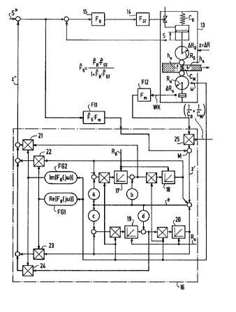
Figure 6 depicts a position control for the
positioning of a schematically depicted roll stand 13.
This roll stand 13 is comprised of an upper backing roll
with the radius RQ, a lower backing roll with the radius
Ru, two working rolls of smaller diameter, a hydraulic
piston which effects the adjustment of the upper backing
roll and, belonging to the piston, a hydraulic cylinder,
which is supported on the supporting framework. The
flexible supporting framework is represented
symbolically by a spring with the spring constant Co.
The rolled stock, which in the roll nip is assigned an
equivalent material spring with the spring constant Cy~,
is rolled by means of the two working rolls from the
inflow thickness h~ down to the outflaw thickness h~.
The eccentricity of the upper and the lower backing roll
is caused by the rolls wearing unevenly, by deformations
due to thermal stresses and by deviations of the
geometric cylinder axes of the rolls from the axes of
~1~~~~~.~~
- 22 -
rotation which arise during operation. They are denoted
by ~ RO and ~ R~i respectively ( i . a as deviations from the
ideal banking roll radii R~ and Ru, respectively), The
sum of the influences of these deviations can be
designated by a total roll eccentricity ~ R and
represents a periodically acting disturbance variable z.
Measurement 'transducers are provided for the backing
roll rotational frequency (~ , usually in the form of a
tachodynamo coupled to the driving motor, for the roll
force Wf~ exerted by the hydraulic piston and for the
roll starting position, which corresponds to the
relative position S of the hydraulic piston moving the
upper backing roll. 14 denotes a trigger element, by
means of which the hydraulic piston is pressurized with
pressure oil through a valve. The actuating signal for
the trigger element 14 consists in the output signal of
a position controller 15, whose nominal value is the
signal S*. In the case of such a position control, the
European Patent EP 170 016 B1 proposes, inter alia,
feeding the measured-value signal S, the measured-value
signal corresponding to the roll force Wit, and the
rotational-frequency measuring signal tsJ to a roll-
eccentricity compensator, denoted therein by RECO, and
to subtract the output signal of this compensator from
the measured value signal S. The effect of roll
eccentricities can only be adequately compensated for
when one can assume that measured values are smoothed to
a degree which is small enough and when a dynamic,
d a 2,,i._
-- 2 3 -
exceptionally first-rate starting hydraulics is
provided.
Figure 6 depia~ts the improvement, according to the
invention, of the known roll-eccentricity compensator,
which lies in precisely eliminating the influence of
roll eccentricities for cases where these conditions are
not given. Apart from another instance of signals being
applied to the input side of the roll-eccentricity
compensator, this improvement lies in that the output
signals of the integrator pairs 17, 18, and 19, 20,
simulating the roll eccentricity ~ R as a model, are fed
respectively to the multipliers 21, 22, 23, 24, and the
second inputs of these multipliers are acted upon by
frequency-controlled function generators FG1, FG2 for
Z5 the real and imaginary part of the correction frequency
operation. The sum of the output signals of the
multipliers is then added to the nominal value S* of the
position controller 15.
On the input side, the output signals of two
filters FI1 and FI2 are applied to the roll-eccentricity
compensator 16. The filter.Fl2..is a smoothing filter:
for the measured value of the roll force WK with the
transfer function F~. The input variable of the
position control loop is carried over the filter FI1
with the transfer function FB . F~, whereby ~"B = F~ '
FsTJ(1 + ~~ ° Fs~) is the simulated transfer function of
the position control loop, where F~ and Fs~ are the
simulated transfer functions of the position controller
~~,~~,.~'~x~~
2~
15, and of the final controlling element 7.4,
respectively. Since the output signal of the filter F12
is weighted by means of the multiplier 25 with the sum
of the inverse values of vhe supporting-framework spring
constant Co and of the material spring constant C~ and
thus the response characteristic of the roll. nip is
compensated for, the variable z' appears at the output
of the mixing element, which variable is dependent
solely upon the respective, acting disturbance variable,
that is of the eccentricity R. This variable z' is
then simulated in a well known manner by the disturbance
variable detector consisting of the integrators 17, 18,
and 19, 20, and, by means of the function generators FG1
and FG2, as well as of the multipliers 20 to 23,
subjected in a frequency-selective manner to the
correction frequency operation
F~~jW ) = 1
Fs(jW )'F~fj~)
The output variable z" is then added to the nominal
value S* of the position control loop in the manner
'thereby compensating for the disturbance variable z.