Note: Descriptions are shown in the official language in which they were submitted.
BALANCE PISTON AND SEAL ARRANGEMENT
This invention relates generally to centrifugal compressors and,
more particularly, to a method and apparatus for providing a seal
between an oil-fed transmission chamber and the relatively low
pressure area in a balance piston adjacent the impeller.
In order to counteract the aerodynamic thrust that is developed
by the impeller of a centrifugal compressor, it is well known to
employ a balance piston consisting of a low pressure cavity
behind the impeller wheel. Because of thè tendency for
lubricating oil to leak from the transmission into this low
pressure area, it is also common practice to install a seal
device between the balance piston and the transmission. A
mechanical seal, such as a carbon face seal, is typically used
for this purpose. However, besides being very intricate,
delicate and expensive, these mechanical seals introduce
substantial mechanical losses due to viscous drag from relative
motion between mating surfaces.
An alternative is a labyrinth seal which is simple, rugged,
inexpensive and, since it is noncontacting, there is virtually no
mechanical losses due to rubbing. The disadvantage, however, is
that in order to be entirely effective, it is necessary to
pressurize the labyrinth seal. One known way to do so in a
centrifugal compressor is to fluidly connect a source of high
pressure gas from the discharge line to the center of the
labyrinth. In this way, oil leakage from the transmission is
substantially eliminated.
A disadvantage of such a pressurized labyrinth seal as recognized
by the Applicants is that the high pressure gas at the labyrinth
will tend to flow into the balance piston and the transmission
chamber, and if the flow becomes excessive, the overall
~'J~
efficiency of the compressor will suffer. Further, the flow into
the balance piston will tend to degrade its performance.
In particular, with regard to efficiency losses in higher
pressure systems, such as a centrifugal compressor designed for
an operation with a high density refrigerant such as R-22, the
pressure differential between the compressor discharge line and
the transmission, and even more so, the pressure differential
between the discharge line and the balance piston, can be
sufficiently high that there will be a substantial flow of
refrigerant gas to the balance piston and into the transmission.
The transmission is vented by means of a pipe back to compressor
suction. Also, the balance piston is ported to compressor
suction. Thus, any high pressure gas leaking in either direction
ends up being re-compressed and is therefore cause for a loss in
efficiency.
It is therefore an object of the present invention to provide an
improved labyrinth seal arrangement for a centrifugal compressor.
Another object of the present invention is the provision in a
centrifugal compressor for the effective and efficient use of a
balance piston.
Yet another object of the present invention is the provision in a
centrifugal compressor for maintaining an effective and efficient
seal between the transmission and a low pressure cavity of a
balance piston structure.
Still another object of the present invention is the provision in
a centrifugal compressor for reducing the leakage of high
pressure labyrinth seal gas to a balance piston cavity.
Yet anothex object of the present invention is the provision in a
centrifugal compressor for a labyrinth seal arrangement which is
economical to manufacture and reliable and effective in use.
These objects and other features and advantages become more
readily apparent upon reference to the following description when
taken in conjunction with the appended drawings. These objects
are achieved in an apparatus and method according to the
preambles of the claims and by the features of the characterizing
parts thereof.
Briefly, in accordance with one aspect of the invention, a
labyrinth seal, between the transmission and balance piston of a
centrifugal compressor, is pressurized by a source of pressurized
gas which is maintained at a pressure slightly above the pressure
in the transmission. This slight pressure differential is
sufficient to prevent oil from migrating out of the transmission
and yet is not so great as to cause excessive amounts of gas to
flow into the balance piston and transmission.
By another aspect of the invention, the gas which is supplied to
pressurize the labyrinth is taken from a motor chamber which is
vented to the cooler. Refrigerant gas, generated in the motor
chamber during the motor cooling process, is allowed to flow to
the cooler in a manner controlled by a back-pressure valve. This
valve acts to maintain a fixed pressure differential between the
motor shell and the cooler and to thus provide a source of
pressurized gas to the labyrinth seal at a pressure that is
slightly above that in the transmission and not significantly
higher than that in the balance piston.
In the drawings as hereinafter described, a preferred embodiment
is depicted; however, various other modifications and alternate
; 3 ~
constructions can be made thereto without departing from the true
spirit and scope of the i~vention.
Figure 1 is a longitudinal cross-sectional view of a centrifugal
compressor having the ba~ance piston and seal arrangement of the
pre~ent invention incorporated therein.
Figure 2 is an enlarged view of a portion thereof showing details
of the labyrinth seal portion of the invention.
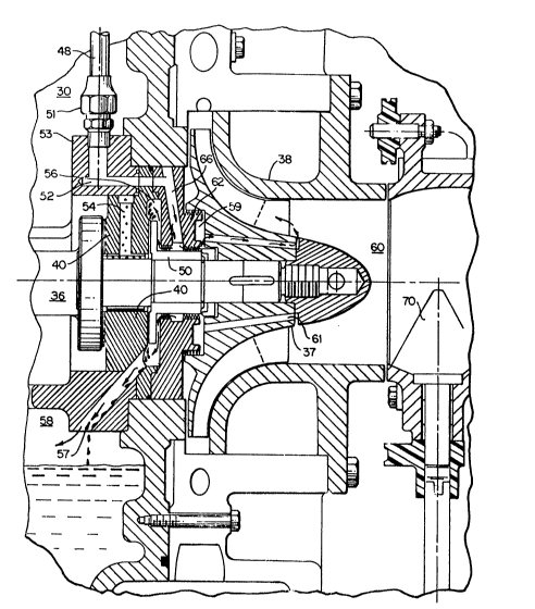
Referring now to Figure l, the ~nvention is shown ~enerally at 10
as embodied in a centr~fugal ccmpressor system 11 having an
electric motor 12 at its one end and a centrifugal compressor 13
at its other end, with the two being interconnected by a
transmission 14.
The motor 12 includes an outer casing 16 with a stator coil 17
disposed around its inner circumference. The rotor 18 is then
rotatably d~sposed within the stator winding 17 by way o~ a rotor
shaft 19 which is overhung from, and supported by, the
transmission 14. The transmission 14 includes a transmission
case 21 having a radially extending annular flange 22 which is
secured between the motor casing i6 and the compressor casing 23
by a plurality of bolts 24, with the transmission case 21 and the
compressor casing partially defining a transmission chamber 30.
Rotatably mounted within the transmission case 21, by way of a
pair o~ axially spaced bearings 26 and 27 is a transmission shaft
28 which is pre~erably integrally formed as an extension of the
motor shaft l9. The collar 29, which is an integral part of the
shaft or attached by shrink ~itting, is provided to transmit the
thrust forces from the ~haft 28 to the thrust bearing portion of
the bearing 26. 'rhe end of shaft 28 extends beyond the
transmission case 21 where a drive gear 31 is attached thereto by
way of a retaining plate 32 and a bolt 33. The drive gear 31
2 'v ~
engages a driven gear 34 which in turn drives a high speed shaft
36 for directly driving the compressor impeller 37. The high
speed shaft 3G is supported by journal bearings 39 and 40.
In order to reduce windage losses in '_he transmission 14 and to
prevent oil losses from the transmission chamber 30, the
transmission chamber 30 is vented to the lowest pressure in the
system (i.e., compressor suction pressure) by way of passage 55,
tube 65, and compressor suction pipe 75. As will be explained
hereinafter, this flow path can be a cause of lost efficiency
unless provision is made in accordance with the present
invention.
In order to cool the motor 12, liquid refrigerant is introduced
from the condenser (not shown) into one end 41 of the motor 12 by
way of an injection port 42. Liquid refrigerant, which is
represented by the numeral 43, enters the motor chamber 45 and
boils to cool the motor 12, with the refrigerant gas then
returning to the cooler by way of a conduit 44. A back pressure
valve 46 is included in the conduit 44 in order to maintain a
predetermined pressure differential (i.e., about 5-6 psi) between
the motor chamber 45 and the cooler, which typically operates at
about 80 psia. Compressor suction pipe 75, at the point where
transmission vent tube 65 is connected, is typically at a
pressure 1-2 psi less than the cooler. This establishes a
transmission pressure of about 78-79 psia. Thus, the pressure in
the motor chamber is maintained at 85-86 psia, which is about 6-8
psia or 7.6-10.3% above that in the transmission chamber 30.
Also, fluidly communicating with the motor chamber 45 is an
opening 47 in the annular flange 22 of the transmission case 21.
A line 48 is attached at its one end to the opening 47 by way of
a standard coupling member 49. At the other end of the line 48
is a coupling member 51 which fluidly connects the line 48 to a
passage 52 formed in flange member 53 as shown in figure 1 and as
can be better seen in figure 2. The bearing 40 functions as both
a journal bearing to maintain the radial position of the shaft 36
and as a thrust bearing to maintain the axial position thereof.
An oil feed passage 54 is provided as a conduit for oil flowing
radially inwardly to the bearing surfaces, and an oil slinger 50
is provided to sling the oil radially outward from the shaft 36.
An annular cavity 56 then functions to receive the oil which is
slung off from the bearing 40 and to facilitate the drainage of
oil through a passage 57 and back to the sump 58. It is this
path which, together with the flowpath mentioned above, can be a
cause of loss in efficiency unless corrective provisions are made
as will be described hereinafter.
In order to provide a counteraction to the aerodynamic thrust
that is developed by the impeller 37, a "balance piston" is
provided by way of a low pressure cavity 59 behind the impeller
wheel 37. A passage 61 is provided in the impeller 37 in order
to maintain the pressure in the cavity 59 at the same low
pressure as the compressor suction indicated generally by the
numeral 60. This pressure (downstream of the guide vanes 70)
typically varies from around 77 psia at full load, down to 40
psia at 10% load. Since the pressure in the transmission casing
is higher (i.e., equal to the compressor suction pressure
upstream of the inlet guide vanes 70, or about 78-79 psia) than
that in the cavity 59, and especially at part load operation, a
labyrinth seal 62 with its associated teeth 63 is provided
between the bearing 40 and the impeller 37 to seal that area
against the flow of oil from the transmission into the balance
piston 59. This concept is well known as is the further concept
of pressurizing the labyrinth seal by exerting a high pressure
gas thereon. If, as is customary, high pressure gas from the
discharge line is used to pressurize the labyrinth seal 62, then
the substantial pressure differential will cause the high
pressure vapor, (i.e. around 200 psia) to flow from the labyrinth
seal 62 to the low pressure sections of the system to thereby
reduce the efficiency thereof. This flow can occur in two
directions as indicated by the arrows in figures 1 and 2. It can
flow along passage 61 to the compression suction 60 or it can
flow along passage 57 to the sump 58, from where it can flow as
indicated by the arrows in figure 1, through the vent opening 55,
the tube 65, the suction pipe 75 and finally to the compressor
suction 60.
In order to prevent these losses, the labyrinth seal 62 has
instead, been pressurized with the refrigerant vapor in the motor
chamber 45, which vapor passes through the line 48, the passage
52, and a passage 66 in the labyrinth seal 62. Thus, the
labyrinth seal 62 is pressurized at the motor casing pressure of
85-86 psia, which is 6-8 psi above the transmission pressure.
With this pressure differential being so minimized, the losses
that would result from the labyrinth pressurization gas leaking
back into the transmission and eventually into the compressor
suction 60 is therefore also minimized. Similarly, with the
pressure differential between the labyrinth seal 62 and the
compressor suction 60 being minimized, the losses that result
from the leakage of labyrinth pressurization gas leaking directly
into the compressor suction 60 by way of the passage 61 is also
minimized.
It will therefore be seen that the present invention not only
provides the advantages of using a labyrinth seal for isolating
the transmission chamber 30 from a balance piston in a
centrifugal compressor, but also provides a novel and practical
means of pressurizing the labyrinth seal in a manner which
optimizes the efficiency of the system.