Note: Descriptions are shown in the official language in which they were submitted.
2 ~ ~ a ~
VIDEo TRANSMISSION AND CONTROL SYSTEM UTILIzING - - -
INTERNAL TELEPHONE LINES -~
BACKGROUND OF THE INvENTIoN ~ ~ -
The pre8ent invention relates to a system for
transmitting gignals between components of a video sy~
tem over the telephone wiring of a residence.
Until the late 1970 8, it was very unu8ual for
ordinary consumer8 to own electronlc devices that
generated or 8upplied video signals. Virtually all ~- -
video programs viewed on television sets were received
"over the air". Thi8 situation changed over the past -
decade as VCR8, video cameras, cable converters, and
home satellite systems became popular.
Currently, many consumers are able to watch video
programs at different locations because they own more ;~
than one television set. When viewing programs from one
of the sources mentioned above rather than those picked ~ ;
up "over the air", however, lt is necessary to convey
the signal from the video source to the television set. -~
When source and receiver are located in the same room,
connecting the two with a coaxial cable is usually the ~ -
easiest method. VCRs and cable converters are nearly
always connected to nearby television sets in this
manner.
When the source and receiver are not located in the 1~ `
same area, a network of coaxial cabling extending
through the residence is a fine solution. Most residen~
ce~, however, are not wired this way, or have networks
that do not allow access at all desired locations.
Furthermore, most consumer~ insist that the wiring be
neatly installed or kept entirely out of sight, making
lnstallation of a network very difficult and unwieldy.
This presents a problem when connection between a video
source and a television requires wiring that extends ` ~-`
., ,. ~.. .
, . , - ,
"":'~r:
2 ~ 2 ~
between rooms, e~pecially rooms located far from each
other, or on different levels. ~ -
Today, it is very common for a residence to include
a VCR and a television located in a "sitting room", and
a Recond television located in a bedroom. This has
generated an enormous demand for technology that trans~
mits video acro8s a residence wlthout requiring instal- `~ :~
lation of new wires. Possible solutions are to broad-
cast the signal at low power, or to use power lines or
telephone wiring, which are always available, as a
conductive path.
Broadcasting i8 currently not feasible in the U.S.
because of FCC regulations, and i~ not feasible in most
other countries for similar reasons. (Several consumer
devices that broadcast video at low power have been
marketed, however, despite their clear violation of FCC
regulations. Thi# testifies to the existence of a large
demand for transmission of vldeo over short distances.)
In addition to legal obstacles, the possibility of
unintended reception of broadcast signals outside
residences, and the possibility of interference from
other sources broadcasting at the same frequency also
present problems.
Regulations covering transmission between source
and receiver over conductive paths are much less res-
trictlve, and signals transmitted by this method are
much le~8 likely to encounter interference from other ;` ~ -~
~ignals or be open to interception. Transmission across ~
power wiring i8 very difficult, however, because ap- ~-
pliances typically attached to those networks often ;~
impart electrical noise at many different radio frequen-
cies, creating a high potential for interference.
Furthermore, a reliable conductive path is not always
available acros~ "use boxes", causing problems when
2 ~
~- ,~,,.
2 ~ 2 ~ ~ 4 ~
source and receiver derive power from different cir~
cuits.
The difficulties in transmitting video by broad-
casting or by conduction over power lines leave conduc-
tion over telephone wiring as the sole remaining option.
This technique also involves very serious technological
and legal challenges, however, and no solution has been
found.
The most obvious difficulties are avoiding inter-
ference with telephone communicatlons and conforming
with all regulations that govern devices that connect to
the public telephone network. Because telephone wiring
in the US and many other countrles typically includes
four conductors, only two of whieh are used for eom-
munications in residences served by a single telephone
number, availability of the unused pair would seem to
present an interesting opportunity for avoiding these
problems. Unfortunately, wlring installers often do not
connect the unused pair at the network junctions,
leaving breaks in the conductive paths offered by these
wires.
The path supplied by the active pair, on the other
hand, is guaranteed to be continuous between two jacks
as long as telephone devices become active when con-
nected at those jacks. An exception is residences where
eaeh jack is wired directly to a central electronic
switehlng unit that provides an interface to the public
tolephone system. The conductive paths between jacks
are likely to be broken across this unit.
There are other technical and legal problems
associated with transmission over this wiring beyond
those ereated by the eonneetion to a publie or private
telephone network. The technieal problems derive from
tho fact that transmission of video was not a considera-
tlon when standards for wire properties, installation
, . :.,:
.......
,.., .~ :.::
,:. ";. ',....
2 ~ 2 ~
and connection techniques, and telephone electronics
were established. Because these are all factors that
can influence the ability of the wiring to reliably
transmit high quality RF signals, this environment is
poorly suited for transmigsion of video.
Further legal problems derive from the fact that
all RF signalg conducted across unshielded wiring will
broadcast at least some electromagnetic radiation.
(Unlike coaxial cable, telephone wiring is not shielded
by a grounded metallic conductor that eliminates radia-
tion.) Because restrictions on RF radiation are very
limiting in the US and most other countries~ they can
potentially defeat any particular electronic technique
that could otherwise successfully achieve transmission.
Systems have been developed to transmit video
signals over ordinary telephone wiring, but none i9
practical for the residentlal application described.
Chou (U.S. Patent No. 4,054,910) discloses a system for
transmitting video over an ordinary pair of wires
without boosting the video signal in frequency. Video
signals transmitted by devices that follow that design,
however, would include energy at low frequencie~ that
would interfere with telephone signals.
Tatsuzawa (U.S. Patent No. 3,974,337) discloses a
system that ~lightly boosts video signals in frequency
(by approximately .5 Mhz) to prevent conflict with
voiceband communications. The system also requires,
howover, a sophisticated procedure for compressing the
bandwidth of the signal 80 as to avold use of energies
at the higher frequencies, which attenuate quickly.
Further, the higher end of the resulting band is "pree-
mphasized", or amplified more than the lower frequen-
cies, in order to account for the remaining differences
in attenuation.
~ .
The purpose of the technique disclose~ by Tatsuzawa
i~ to allow video 8ignalg to travel digtance~ on the
order of 1 km or more. The electronics that reduce and
expand the 8ignal bandwidth however, are very expensive.
There is al5e a major difficulty in that the preemphasis
of the signal mu8t be adjusted depending on the distance
between source and receiver. This i8 of significant
inconvenience to a consumer. Further, the system
depends on electrical characterlstics particular to
frequencies between 0 and 4 Mhz, limiting the transmis~
sion frequency to that band. This creates legal prob-
lem~ becau~e in the U.S., for example, regulation~
severely limit the RF energy below 6 Mhz that can be fed
to wiring that is connected to the public telephone
network. Finally, the restriction to a single band
allows for transmission of only a single signal.
There are countles~ mothods for reducing the
resolution or the refresh rate of a video signal in
order to reduce the bandwidth enough to avoid the
problem of attenuation, e.g. Lemelson (U.S. Patent No.
4,485,400). Current video standards in the U.S. and
el~ewhere, however, use a refresh rate just quick enough
to avoid annoying "flickering" of the picture. Because
most consumers have little tolerance for "flickering" or
a reduced picture quality, these technique~ do not
present solutions to the problem at hand.
Two commerclally available devices are known by the
inventors to transmit uncompromised video across tele~
phone wiring. The first device is marketed by several
cable equipment supply companies, e.g. the J411 system
marketed by Javelin Electronics of Torrance, CA. The
list prlce of this devlce 18 nearly $1000.
The device transmits a single unmodulated video
slgnal across the,wiring. Because some of the energy of
these ~ignals is concentrated at frequencies below 3
~: . .
2 ~
khz, the device will cau5e interference with telephone
communications. Further, the specifications stipulate
that "transmis8ion must be via dedicated twisted pair
(of which telephone wiring i8 a sub~et) ... and must be ~-
clean, unloaded, and unconnected to any other device."
The device al80 ~pre-empha~izes" the signal by imparting
more amplification at the higher freguencies~ adding
expense and the inconvenience of requiring adjustment on
the part of the user.
The second device, "Tele-Ma~Zic," is marketed by
Impact 2000, a catalog specializing in consumer elec-
tronic devices. Thia device is composed of a pair of
identical connecting cables. These cableZ~ are adver- ~Z~
tised a~ enabling one to connect a video qource to a
residential telephone line in one area, and a television
receiver in a second area, for the purpose of viewing
the source at the second location.
Each cable consists of a classic matching trans-
former which connecta to the video devices, a capacitor
for blocking telephone signals to prevent interference,
and a telephone cord terminated with a "male" RJ-11
plug, the standard plug for connection to a telephone
Zl ack. !
The device is intended to work by aimply feeding
the video signal rom the source on to the wiring, and
recovering it at a remote location. For several
reaZlllrlllon~ it does not nearly solve the problem at hand. -~
To begin with, because "Tele-Ma Zl ic" does not
provide a video amplifier, the strength of the signal
fed to the wiring will be limited by the strength of the
signal supplied by the source. This causes a problem
because the output signZbl levels generated by VCRs sold
in the U.S. are limited by law to approximately lOdB re
lmV into 75 ohms. At thi~ level, the video signal can
transmit only a few feet before the wiring will at-
~ .
~ ! :Z~
2 ~ 2 ~
tenuate its energy below the level required for qualitytelevision reception.
Beyond the limitations caused by low signal power,
the matching transformer of the "Tele-Majic", which
constitutes half of the electronics in the device, is
significantly suboptimal, and does not teach anything
about the correct purpose of that component. In an
apparent attempt to economize, the common 75 ohm/300 ohm
matching transformer, built to connect between 75 ohm
coaxial cabling and "twin-lead" wiring was chosen.
Because matching transformers of the same design are
included with virtually every video device sold in the
U.S., these are extremely inexpen~ive to obtain.
A matching transformer can serve the purpose of
matching the impedance of video equipment to telephone
wiring. The impedance of typical telephone wiring,
however is approximately 100 ohms at low VHF channels,
not 300 ohms. Thi~ will create an impedance mismatch,
and video signals will lose more energy than is neces-
sary when passing from the source onto the network viathis cable.
The transformer can also serve the purpose of ~ i; ,y
balancing the voltages on the two leads of the telephone
wiring, in order to reduce electromagnetic radiation.
Because the transormer used by "Tele-Ma~ic" i8 designed
to handle signals at all video frequencies, however, it i~`~
cannot balance the video signal nearly as well as a
tran~former specifically tailored for a specific fre-
quency. The lack of balance will cause more radiation
than would be released by a maximally balanced signal.
Another problem is that complete isolation of ~ 1
telephone signals using the particular transformer jii
~upplied with the device require~ two capacitors rather `~
than the single one which comes with "Tele-Ma~ic". This
design flaw will cause total disruption of telephone
.
2 ~
communications when the device is connected to a coaxial
port whose outer shield connects to ground.
Given the ability to tran8mit video signals
throughout a residence, the viewer of signals at a
remote television remains limited in the ability to
control the apparatus that supplieg the gignal. Many
video sources, especially VCRs and cable converters, are
designed to cooperate with hand-held controllers that
send out infrared control signals upon command of the
user. Unfortunately, signals from these devices do not
travel between rooms unless there 18 a line-of-sight
path between transmitter and source. It follows that a
significant demand for tran~misslon of control signals
should arise as a result of technology that succeeds in
transmitting video across telephone wiring. Further-
more, there is an obvious economy in achieving this
transmission using the same wlrlng used for transmitting
video.
Robbins (U.S. Patent No. 4,509,211) discloses the
only known method for transmitting control signals from
an infrared transmitter over a transmission line that
also is used to transmit video signals. That ~ethod
converts the infrared signals received in the area of a
television to electrical impulses, which, due to the
nature of typical infrared control signals, are con-
centrated at frequencies below 1 Mhz, lower than typical
vldoo frequencles. Those impulses are trans~itted
acro~ the transmission line to the area of a program-
mable video source, where they are converted back to
infrared energy, recreating the original light pattern.
The technology taught by Robbin~, however, is not
adeguate for situations where the energy of other
signal~ sharing the transmi~sion line is concentrated at
frequencies that fall within the frequency bands that5 confine the control signal energy. This is the case
~: , .:,',.
~2~3 ~
when active telephone wiring 8erve8 a8 the transmis~ion
line. Under the method Robbins discloses, signals from
infrared controllers will conflict with telephone
communication signals because they both have information
content at frequencies between 0 and 3 khz. Any recei-
ver that i~ tuned to frequencies between 0 and approxi-
mately 3 khz, such as a telephone get, will react to
both telephone signals and control signals. Either
telephone communications will be noisy, or the infrared
signals will be ambiguous, or both. (If one signal i8
much stronger than the other, that signal may be
received without distortion.) Furthermore, the ~ystem
will fail whether or not video slgnals are present.
Robbins discloses devices that lnclude, in combina-
tion with other technology, "isolation circuitry" whichprevents the electrical signals derived from infrared
light patterns from reaching the video source and the
television receiver. Robblne teaches that "power lines,
telephone lines or other existlng conductor systems can
be used, providing the various signals do not interfere,
or providing isolation means are provided." This is
incorrect. If two signals overlap in frequency, no
isolation means will cleanly separate them 80 that only
the deeired signal reaches the receiver that is de~igned
to react to it.
Indeed, the isolation circuitry disclosed is
totally unnecessary even for the very application that
18 tho focus of the Robbins patent. Under the system
Robbine discloses, video signale and control signals
tran~mit across a single conductlve path at non-over-
lapping frequencies, and isolation circuitry is provided
to block the control signal~ from the video source and
the television receiver connected to this path. Because
VCRs and virtually all other video sources have reverse5 isolation provided at their output ports, electrical
g
.;. '~,:
:`.'.',', .'',` ,.
2 ~ 2 ~
energy incident at the~e port8 will have no effect at
all, and extra iSolation is not required. Further, when
a television is tuned to a particular video channel,
signals at frequencie~ out~ide of that channel are ~ -
ignored unle~s their energy level i8 very high. The
control signals will be ignored in thig manner, just as
video signals at VHF channel 3 and VHF channel 5 are ~ -~
ignored by a television receiver tuned to VHF channel 4.
Beyond Robbins' incorrect teachinq of i~olation
circuitry and the fact that the infrared transmission
system he teaches is inadequate for the pre~ent applica~
tion, Robbins teaches nothing regarding tran~mis~ion of
video over telephone wiring.
An electronic transmitter/recelver pair called the
Rabbit follows the electronic prlnciples disclosed in
Robbins' patent to send video and infrared signals ~ ~-
between a VCR and television. This device, which cites
the Robbins patent on its packaging, has been available
at retail outlets since 1985. It uses a transmission
line composed of a single very thin insulated wire pair
which must be installed by the user between the VC~ and
a television. Thus, it embodies the very difficulty
that the current invention seeks to address. ~ ;
There is another system known for transmitting
lnfrared signals from a television to a remotely located
VCR, but it differs in that it uses broadcast technology
rather than a transmission line. Called the "Remote
Extender" and marketed by Windsurfer Manufacturing of
DeFuniak Springs, Fla, this device converts the infrared
signals to electrical impulses, then boosts these
lmpulses to a UHF frequency and feeds them to an antenna
from which they broadcast. A remotely located receiver
plcks up these UHF signals, downshifts them back to
thelr original frequency band, and u~es the resulting
impulses to recreate the original infrared pattern.
' ~
. :. '.-~: ~.
:.. . ~.:
...~ .., ~':
,, :~
. : .. ~ .
2 ~ 2 ~ ~ 4 ~
Because this system use8 broadcast technology, it
is much more SUSCeptible to interference, and its -~
receiver has the potential of mi8takenly picking up -~
control signals from the transmitter of a second trans~
mit/receive pair operating nearby. Furthermore, it is
obviously more economical to use the telephone wiring
for transmitting control signals when combining with ~-
technology that transmits video using that medium. -~
. : . . . ~ , ,
The simultaneous trancmiss$on of infrared control
signals and a single video signal across telephone
wiring is the major focus of the technology disclosed
herein. It is easy to see, however, the usefulness of
extending this technology to allow ~ignals from more
than one video source to transmit at a given time. i`~
When each source transmits a signal at a different
frequency band, the telephone wire medium should present ,~
no barrier to the use by multlple qources. Many fac-
tors, however, limit the number of bands that are
available. An especially reetrictive limit, of course,
is imposed by the difficulties of using telephone wiring
as a medium. In the event that the number of desired
sources exceeds the number of available channels, this
limit becomes re~trictive.
If a viewer can disable all but one of multiple
sources that use the same band, however, the picture
from the remaining source can be displayed without
interference. Thi~ possibility creates a demand for a
technique that allows a user to quickly, conveniently,
and remotely activate one of several sources that are
connected and ready to transmit.
SUMMARY OF THE INVENTION
In view of the foregoing, one ob~ect of the present
invention i~ to overcome the difficulties of transmis- i~
11 `'' ~"~'
..., ; .,..~......
, :,~, ...'~,' .
2 ~ 2 ~
sion of video signal8 and control 9ignals from infrared
transmitters across active network8 of telephone wiring.
In accordance with this and other objects, the
present invention include8 a pair of transceivers: a
first transceiver which i8 degigned for connection
between a video source and a telephone jack or other
port of access to a network of telephone wiring, and a
cooperating transceiver which is designed for connection
between an ordinary television receiver and a telephone
jack. These transceivers take advantage of the simple
two-wire conductive paths provided by the wiring of
ordinary residential telephone systems, and thus provide
the following results, in stark contrast to known
techniques discussed above~
lS 1) Each television that is connected via a trans-
ceiver can display, in addition to any of the other
signals otherwise available to it, the signal from any
video source connected via a cooperating transceiver as
described above.
2) An unlimited number of televisions can connect
and operate cimultaneously. Each television can select
any of the connected sources for display at any time, as
long as the source is active, i.e. conducting its
signals onto the telephone network wiring.
3) The number of sources that can be active at once
will depend on many different factors, but will always
be greater than one. The signals from each active
source occupy different, non-overlapping frequency bands
while transmitting across the wiring.
4) Any number of sources can share a single fre-
guency band, but only one of that group can be active at
a given time. The transceivers that connect to the
video sources will include one of two technologies for
allowing a viewer at any television to remotely and
12
'~,',,,'. ~,
.- :. ,' ~''-, '
-:- 2a2~
conveniently switch the identity of the active source
that i8 using a particular band.
5) Any video sources that re~pond to control
signals from infrared transmitter8 and are connected via
a transceiver as described above can be controlled from
any area where a connected television is located,
whether or not such area i8 within a line of sight of
the video source.
6) Operation of telephone and other low-frequency
communication, including that conducted by intercoms,
fax machine~, and modems, is not affected by the connec-
tion and operation of any of the devices herein des-
cribed.
7) All of the capabilities described above are
provided by simple connection of the transceivers. No
other effort on the part of the user is reguired.
In addition to these and other ob~ects and results,
a design is disclosed for a special television that
connects directly to a telephone network. This tele-
vision is designed to cooperate with the video sourcetransceiver mentioned above. It includes electronics
for deriving video signals from the wiring and tuning to
them, and will transmit the intelligence of infrared
control signals that it detects back over the wiring to
the transceiver for control of its connected video
source. Like the transceivers, it causes no inter-
ference with telephone communications.
A further design is disclo~ed for an inexpensive
device that, in combination with the disclo~ed trans-
ceivera and television, provide~ the above capabilitiesto residences eguipped with special telephone systems
that include a central electronic switching unit.
'.: :."': '. ,' ''
,'.,':,~,: ';'"','. .
13
~'~''''',,"','''
...,.,:, ,: ,',
BRIEF DESCRIPTION OF THE DRAWINGS
Figure l is a block diagram that illustrates the
fundamental components of the video 90urce transceiver
and how those componentS interact with one another.
Figure 2 is a block diagram that illustrates the
fundamental components of the trangceiver that connect9
to a television and how those components interact with
one another. -
Figure 3 is a chart which describes the three `~
systems disclosed for cooperation between RF conversion
components of the two transceivers. ~-
Figure 4 is a block diagram showing how special :-
components can be included within an ordinary television
to provide for recovery of video signalc from active
telephone networks and for transmission of control
signals onto those networks for reception by a cooperat-
ing transceiver.
Figure 5 shows the electronics of an adaptor
designed to allow transmis~ion of RF enerqy acro~s
telephone networks that include a central switching
unit.
Figure 6 shows the electronics used within the
video source transceiver for coupling to an active
telephone network.
Figure 7 show~ the electronics used within the
tran~ceiver that connects to a television for coupling
to an active telephone network.
Eigure 3 show~ the details of the circuitry that
convert~ infrared light to electrical energy at frequen-
cies above the telephone voiceband.
Figure 9 show~ the details of the circuitry that
creates an lnfrared light pattern from an electrical
signal above the telephone voiceband.
'' ' "": ''"'
14 ~
~ .. ,~ . . .
'': ... ... .
2 ~ 2 ~
DETAILED DESCRIPTION OF THE PREFERRED EMBODIMENT
The devices disclosed herein provide for transmis~
sion of video signals and control signals from infrared
transmitters across active network9 of telephone wiring
without affecting ordinary telephone communications.
They are designed to accommodate video signals with the
same resolutions and refre8h rateg ag those used for
public broadcasting. When transmitting signals across
path lengths typical of those found in ordinary residen-
ces, the devices provide enough signal fidelity to
produce undegraded images and unambiguous control
commands.
Design of these devices required an extensive
experimental and theoretical investigation of the
physics of transmission of video signals across this
type of network, a deep appreciation of the special need
for convenience and economy ln consumer products, some
circuit design, as well as a novel combination of
electrical signal processing components.
A description of the disclosed devices is preceded
by an overview of the topic of transmission across tele~
phone wiring. The overview will begin with a summary of
the investigation into the transmission of video and
will conclude with a description of the method designed
to transmit signals from infrared controller~
The descriptions that follow the overview include
~everal options for the design of the pair of cooperat-
ing transceivers, the special television/transceiver
pair, and the special adaptor referenced in the summary.
The influence of the transmission investigation on these
designs as well as the influence of other considerations
related to consumer electronics will be included in
those descrlptions. The advantages and disadvantages of
the various designs will also be discussed, and the i i ;`i~ ?'
preerred embodiment will be identified. Finally, the
, ~..,. ~,
':`~.'' ." ~,''
2~293~
electronic details of some circuitrY described in
general terms earlier on will be presented.
The signals described as video herein refer to
signals that provide picture information encoded accord-
ing to NTSC, PAL, SECAM, or similar formats that areused for public broadcasting throughout the world.
These formats provide between 50 and 60 image frames per
second, and vertical resolutions of between 525 and 625
lines per frame.
In general, the disclosed devices are designed to
transmit audio information along with video according to
these formats. Most of the dlsclosed technology,
however, will function the same whether audio is present
or not. For this reason, signals described as video
shall refer to signals with or without audio informa-
tion. An explicit description will be used whenever
audio is specifically included or excluded.
Transmission of Video Sianals across Telephone Wirina
The following problems must be overcome for trans-
mission of video signals to succeed across a network oftelephone wiring~
1) Multi-path effects, also known as "reflections"
or "ghostlng," can cause video distortion. These
effects can arise in a network of wiring because signals
can travel from source to receiver via many different
path~. If signal energy arrives at the receiver across
two paths that differ in length, the signal conducted
across one path will be offset in time relative to the
slgnal traversing the second path. This will cause the
same image to appear at two different points in the
scanning cycle of the picture tube. This can create the
special distortion pattern called "ghosting" if the
offset difference is large enough. Multi-path "ghos-
ting" of broadcast signals is commonly caused by large
16
. . " ,, ..
',' .';:,.,.;"'.J,,~
~ 3~
:. ~. -,: ,:
buildings that reflect broadcast energy and create
multiple paths of significantly different lengths to
nearby antennae.
2) Reduction of signal energy across the transmis~
sion paths can reduce the signal-to-noi8e ratio present
at a television receiver below that required to produce
a high-quality picture. A signal-to-noi8e ratio o 40dB ~:
is marginally sufficient for high-quality video. It
follows that picture degradation will re8ult whenever
signal energy at the receiver falls to within 40dB of
the noise level on the wiring or the minimum noise floor
of the television receiver. -~
Three factors are principally responsible for
attenuation of the energy of the signal as it travels
from ~ource to receiver, resulting in a lower energy at
the end of any transmission path. These factors are: -
a) Attenuation or dissipation of signal energy by
the wiring. Unlike coaxial cable, over which video
~ignals travel with little attenuation, telephone wiring i- p;~
dramatically attenuates high frequency energy. This
attenuation increases linearly with path length, and
also increases with frequency. At 90 Mhz for example, i~`
typical telephone wiring attenuates energy at 14dB per ;
100 feet, while at 175 Mhz, attenuation is approximately ''~ 0
25dB per 100 feet. `
b) Network ~unctions where the wiring splits. ~ ~
These can cause significant attenuation when they occur ~;~$
on one of the principal path~ carrying energy from
source to receiver. When the alternative path is very
long, the energy split~, reducing the level on the main
transmission path by approximately 3.5dB. As the alter-
nate path becomes shorter, attenuation will depend on ~ ~
whether or not the branch is open, or "terminated." If ~;"m; ,~ 3
the branch is unterminated, attenuation will be less
than this amount, and will be negligible for very short ~`
17 i; ~.
~' ~: -:
29~-3~1
branches. At higher frequencieg, the 3.5dB limit ic ap-
proached more quickly.
c) Telephone devices that dissipate high frequency
energy. A significant number of these devices exhibit
thi~ property. If they terminate short branches, as
de~cribed above, they can drain energy from a principal
transmission path. Deviceg that have a ~trong dissipa-
tive effect can reduce the energy beyond the ordinary
3.5dB splitting 1088. As the length of these branches
, :,,: ~ :;,
increases, the attenuation of the branch prevents the
draining phenomenon, and the ordinary 3.SdB splitting
1088 becomes the dominating factor. At higher frequen-
cies, the 3.5dB limit is encountered at shorter path
lengths.
3) The fact that attenuation increases with fre-
quency can cause the energy near the high end of a 6 Mhz
. , :.:.:,
video channel to attenuate more than the energy at the
lower end. This cau~es a "tllt" in the signal power
spectrum, which is a form of signal distortion that can
cause picture degradation if it is sufficiently pro- ;~-
nounced. ~`"'-`!
4) Interference from strong broadcast signals
picked up by the wiring acting as an antenna can cause
severe distortion. The ability of the wiring to receive ;~
broadcast energy increases with frequency. ` ~
5) Because telephone wiring, unlike coaxial cable, ','~,.J,''.~",,~I,.'',',~,'.,
is not shielded by a groundsd metallic conductor, `
signiflcant electromagnetic radiation can be created
when it conducts electrical energy at radio frequencies.
This can create legal problems as well as interference
to nearby televisions and other receivers tuned to those j~
frequencies. The level of radiation caused by a given
signal level lncreases with frequency. (In contrast to
reguations covering radiation, no special legal problems ~;`
are created in the U.S. by the connection of radio
18
2 ~ ~ ~ 3 ~
frequency devices to the public telephone network if
those devices do not transmit energy below 6 Mhz.
Restrictions are not required because the network wiring
will quickly attenuate such energy below any meaningful
level.)
One possible strategy for addressing these problems
i8 to recode the video signal into a different waveform
with equivalent information before imparting its energy
to the wiring. If, for example, the bandwidth of the
signal could be compressed without losing information,
the proolems of tilt, interference, and, possibly,
radiation would be reduced. Implementation of compres-
sion or other recoding techniques, however, is extremely
expensive, and will probably not significantly alleviate
all of these problems.
Because some conventions for video encoding and
modulation provide signals wlth redundant information,
the bandwidth of a video signal can sometime~ be reduced
by sharp filtering without significant loss of informa-
tion. Becau~e the potential reduction would not belarge, however, this strategy i8 also unlikely to
significantly alleviate the problems described above.
A second method of waveform alteration i8 to
amplify the higher frequencie~ of the signal more than
those at the low end. This i~ called "pre-empha~is" and
can compensate for "tilting" of the signal. Apart from
the act that it only addresqes one of the potential
problems, however, pre-emphasis is expensive, and also
reguires the inconvenience of ad~usting the compensation
level upon installation in a new residence. This is
because the attenuation differential is a proportion of
the overall attenuation which, in turn, will vary from
one residence to another.
Beyond rewiring a residence, which defeats the
purpose of the invention, the only other elements of
19 , , `.'~ ~
~''''`'' '''";,'~
:,.".
2 a ,~
control that can be exercised to help transmission
succeed lie in the choice of the energy level and
frequency, and in electronics that can limit the effects
of the connected telephone devices. Most individuals
skilled in the art, however, expect that an amplified
video ~ignal conducted across telephone network~ would
suffer from "ghosting" at most any frequency and energy
level. Others suspect that amplification of the signal
high enough to force it across the wiring would create
completely unacceptable levels of radiation.
To investigate transmission over this network, the
inventors devised and conducted a series of experiments
that included observation of the quality of pictures
generated from transmitted signals, and also measure~
ments of radiation created by the transmitting signals.
As part of the experiment, a transmit/receive pair
was designed, using technology dieclosed later herein,
to feed amplified video eignale through one port on a
network and to recover them from a second port. These
devices were used to perform experiments in twenty
residences using video signals at different energy
levels and frequencies. For most of the experiments,
telephone equipment was disconnected at the involved
ports, but some remained elsewhere on the network. A
few tests were performed to investigate the effects of
telephone equipment sharing the same port.
The radiation tests involved conduction of video
eignal~ on to an unterminated 50 foot length of wiring
that was extended horizontally and elevated one foot
above ground, and measuring field strength via a calib-
rated antenna placed 3 meters from the midpoint of the
wire. The signale were conditioned to minimize radia-
tlon before they were fed to wiring. The conditioning
involved a process called "balancing", which is used in
the di,3closed transceiver,g and i8 described later on.
,"~'~
: s
2 ~i 2 ~
The most natural choice9 for transmission frequen~
cies are the channels in the low VHF range. In the
U.S., the low VHF range i8 composed of VHF channel~ 2
through 6, which extend from 54 Mhz to 88 Mhz. VHF
5channels 2 through 4 constitute one adjacent group of ;~
three 6 Mhz wide channels spanning between 54 Mhz and 72
Mhz, and VHF channelg 5 and 6 constitute a second
adjacent group spanning from 76 Mhz to 88 Mhz.
Channels in the low VHF range are good candidates - :
10for transmission frequencies because they constitute the
lowest group of channels tunable by ordinary televi- `~
sions. The benefit of tunability iB that television
receivers can recover these signals from the wiring in
tunable form, eliminating the need for electronics thatl~;
15convert their frequency. The benefits of using the
lower frequencies among the VHF channels are the atten~
dant reductions in attenuation and radiation. i~
A further advantage of tunability is that if the
channel is not used for local video broadcasting, there
20is no possibility of interference from broadcast energy
picked up by the wiring in the U.S. That is because the
requency bands allocated to video broadcasting in the
U.S. are off limits to any other services.
Because little variation was expected acro~s the ~ S
25low VHF range, tests were conducted only at VHF channel
3. No frequencies above this range were tested because ~ '
the 1rst tunable channel above VHF channel 6 is VHF 7 `
whlch, at 174 Mhz, would exhiblt significantly greater
attonuation and radiation, and would have no redeeming ~-
30advantages over the low VHF channels.
To see if further reductions in attenuation and
radiation would offset the extra costs associated with
u~ing channels below the tunable range, it was decided
to investigate transmisslon at frequencies below ~ F
35channel 2. Because U.S. Federal Communications Commis- -
21
' :'
. ,~i, ~ , . ~..;.
sion radiation limits are less restrictive below 30 Mhz,
it was decided to choose the channel spanning from 24
Mhz to 30 Mhz.
To the inventors~ knowledge, the only applications
involving transmis~ion of video signals with high
resolutions and refregh rates at frequencies below the
tunable range are thoge where extra bandwidth is needed
on a cable TV distribution network. This requirement
can arise when there is a need to send video signals
over cable from remote locations back to a central
tran~mission site. These frequencies are available for
reverse transmission because distribution systems do not
ordinarily use frequencies below VHF channel 2. They
are not tunable by televisions and have never, to the
inventors' knowledge, been used in any consumer video
device.
Following is a summary of the results of the
transmission and radiation experiments~
1) When a VHF channel 3 signal with a conducted
energy level of 37.5dB re lmV was fed onto the wiring at
the source end, visibly undegraded pictures were genera~
ted from signals recovered at a remote ~ack in 85% of
the test cases. Radiation from signals at this energy
level were measured at approximately 200uV/M at 3
meters.
2) At an energy level of 42.5 dB re lmV, video
signals concentrated between 24 Mhz and 30 Mhz succeeded
in genorating a visibly undegraded picture in 100% of
the test cases. Radiation levels were approximately
200uV/M at 3 meters. (This level was the same as the
level for VHF channel 3 becau~e a higher conducted
signal level was used.)
3) Ghosting was never observed at any frequency or
energy level.
22
", , i~
'~'',:-'"~
2 ~ 2 ~ 3 ~
4) Interference from a broadcast video source
distorted the picture only when it was strong enough to
create an undegraded picture via antenna reception.
Distant video sources caused no interference. This type
of interference, of course, applied only to the tests at
VHF channel 3 and not at the 24 Mhz to 30 Mhz channel.
5) Signals from CB radio transceivers, which
operate with 5 watts of power and span the range from
26.965 Mhz to 27.4 Mhz caused interference with trans~
mission across the 24-30 Mhz video channel when a CB
transmitter was within 50 feet of the telephone wiring.
Interference from other sources was not noticed, but i~
obviously possible when a ~ource tranqmitting at an
interfering frequency is close enough or transmit~ with
enough power.
6) The connection of telephone equipment at ports
previou~ly u~ed only by the transceivers occa~ionally
degraded an otherwise high quality picture.
7) No distortion that was noticed could be traced
to "til~ing" of the signal spectrum.
8) Radiation from signals transmitting across the
wiring at VHF channel 3 often caused slight but sig-
nificant interference to nearby televisions tuned to a
VHF 3 signal supplied by a different video source.
This occurred most often when a cable converter and VCR
both connected to a television receiver, and the televi-
sion tuned in a signal rom the cable converter at VHF
channel 3 while the VCR supplied the VHF 3 signal that
was transmitted across the telephone wiring. This type
of interference occurred on older televisions that did
not offer a shielded input port, and also on more modern
televisions that connected via a shielded coaxial cable
but allowed slight leakage from other available ports
such as twin lead ports. Note that this type of problem
wlll not arise when using VHF channels 5 or 6 for
;'"',' ~'
' :''~."',~.'
2 0 2 ~
transmission across the wiring. because video source~
that supply signals at those channels are very rare.
The survival of enough signal energy to gene~ate a
quality picture can be explained by simply considering
the attenuation expected over the longest paths typical~
ly encountered in residences. If one assumes a minimum
television receiver noise figure of 5 dB, a receiver
bandwidth of 6 Mhz, and a desired signal-to-noise ratio
of 50 dB, one finds that the minimum signal level
re~uired at the receiver is 770uV into 75 ohms. The
output level of a typical VCR is approximately 2000 uV
into the same impedance, well above the minimum neces-
sary to reliably provide a high quality picture. At 66
Mhz, attenuation of signals transmitted over telephone
wiring is approximately 30 dB over 250 feet. It follows
that 30 dB of amplification should ensure good signal
quality over the longest path~ in typical households,
except where splits in the wlring and connected tele-
phone equipment cause excessive attenuation.
The lack of "ghosting" can be explained by the fact
that there is usually a monotonic relationship between
signal transit time and attenuation. (The rare excep~
tions to this relationship can be caused by a short path
over which signals suffer extraordinary attenuation due
to the presence of many splits, or the presence of
telephone devices connected off short branches. Signals
traversing such a path might attenuate more than those
traversing a longer path that has a longer transit
time.) Because of this monotonic relationship, secon-
dary signals arriving at the receiver after traversing
long reflected paths will be usually be significantly
attenuated relative to signals that travel over the most
direct path from the transmitter. The "offset" in the
picture that produces "ghosting" is related to the
dlfference in travel times. To be visible, the offset
24
' ~' ~ ' ", '
2a2~g~
mu~t be at least a8 wide a8 the resolution of the
television. It can be ~hown that path length differen- ~-
ces that create offsets this large al~o have enough
difference in attenuation to place the energy level of
the reflected path at least 40dB below that of the
incident path, which is below the minimum SNR required '
for a quality picture, making the reflected energy
negligible and its interference lnvisible. .
The results of the experiments verified that when
two signals are fed to telephone wiring at energy levels
that will cause them to generate the same amount of
electromagnetic radiation, a signal transmitting at a
channel below 54 Mhz has a significantly higher probabi-
lity of generating a high quality picture than a ~ignal
transmitting at a low VHF channel. Transmission at
lower frequencies, however, i8 more susceptible to ~ -
interference from broadcast sources and also requires
somewhat more expen~ive electronics.
Transmission of Signals from Infrared
Controllers across TeleDhone Wirina ~ -
As described in the introduction, the second signal
that will be passed between the transceivers is the
control signal from an infrared transmitter operating in
the area of a connected television. Part of the dis-
clo~ed transmission techniaue follows the known strategy
of transduclng the light pattern created by these
signals into electrical energy and tran~mitting that
energy across the wiring in the opposite direction of '~
the video signals, to be received by the transceiver
connected to the video source. That transceiver uses
the electrlcal version of the signal to recreate the
original infrared light pattern, for the purpo~es of
controlling the video source to which it connects. ,~
`~
:,: :.:":, .
''"' '''''''' "" ''
,~" :. :
~ 9 2 ~ ~ 4 1
The technique disclosed herein embodies an exten~
sion designed to avoid interference with telephone
signal~. The exten8ion call8 for the frequency of the
electrical version of the control signals to be con-
verted to a higher band before tr~nsmis~ion across the
wiring. This band will be high enough to eliminate
interference with telephone or low-frequency communica-
tion signals. After recovery of this signal at the end
of the transmission path, the signal is converted back
to its original band before being used to recreate the
original light pattern.
Maintaining the fidelity of the control signals
across the wiring presents less of a challenge than was
posed by transmission of video signals. Unevenness, or
"tilting" in the signal spectrum is not a problem
because the bandwidth of the signal is small. An
analysis of the factors governing multi-path inter~
ference indicates that that problem should not arise
either.
Because the bandwidth of control signals from
typical infrared transmitters is considerably less than
1 Mhz, finding a frequency interval that will encounter
little interference from ambient broadcast signals is
not difficult. Also, the information content is small
80 that little energy is required for successful trans-
mis8ion. The reduced energy generates less radiation.
Other requirements for the choice of a frequency
band and energy level for transmission of these signals
are that the band must not overlap, of course, the video
signals at the frequencies chosen for video transmis-
sion, and the energy must meet the legal requirements
that govern devices that connect to the public tele~
phone network. As mentioned earlier, the U.S. Federal
Communications Commission impose~ no restrictions on
slgnal~ above 6 Mhz, leaving ample room between that
26
" ~',:: .~,
,", .`~'~',,
' .'~ ~: '~ .".'
": ",.. ,j,,,
2 ~ 2 ~
frequency and the video signals, even if a channel below
VHF 2 is used. The control signals can also be trans~
mitted above the frequencies used for transmission of
video. -~.
A frequency centered at 10.7 Mhz is used in the '~
preferred embodiment because that is a common inter-
mediate frequency in FM radio devices, the result of
which is that there are very inexpensive electronic . - ` .
components available that are especially suited for that
frequency.
Description of the Tran~ceiver
that Connects to a Video Source
As a result of the investigation into transmission
of video signals across active telephone wiring and the
system adopted for transmission of control signals, a
general design for a transceiver was developed to :~
connect between a video source and telephone wiring to
perform the functions of~
1) ~hifting the frequency of the video signal from
the channel supplied by the source to the channel used
for transmission,
2) amplifying the video signal, ;~
3) "balancing" the two leads of the video ~ignal so
that their voltages are nearly equal and opposite with
respect to ground, and matching the impedance of the
telephone wiring,
4) tran~mitting this signal on to the telephone
network without disturbing low~frequency communication :~
signal8, simultaneously recovering the control 8ignal8
ed to the wiring by the transceiver connected to the
television, : : :
5) downshifting the control signals to their ;~
original frequency,
" ';'~.'"'~' .~,,',
, ~ ~ ,,; .
2 0 2 0 ~
6) using the resulting energy to recreate the
original infrared pattern, and
7) connecting to a telephone jack while allowing
for telephone devices to share the same jack without
loading down the energy of the video signal.
Figure 1 shows an arrangement of electronics for a
transceiver 1 designed to implement these functions.
This transceiver is described in the following para~
graphs. The description discloses several optional
design variations.
The transceiver 1 connects to the video source 2 to
derive a signal. That signal is passed to RF converter
3, which translates the signal to the frequency band
chosen for transmission over the wiring.
Fortunately, nearly all consumer video sources
provide their signals in one of only two different ways.
Some devices provide an unmodulated video signal con~
taining no sound information from one port and an
unmodulated audio signal from a second, separate port.
Others supply a video signal, possibly including sound
information, at either VHF channel 3 or 4, according to
a switch set by the con~umer. Most VCRs make their
signal available in both forms.
Two alternative design options for RF converters
are disclosed for transmi~sion at a low VHF channel.
These options have clear advantages over all other
po~sible designs. One design derives the signals from
the port that supplies a low VHF signal, hereinafter
referred to as the "low VHF port." That design is
described first. That description is followed by a
description of the second design, which derives its
signal from the port that supplies an unmodulated
signal, hereinafter referred to as the "baseband" port.
Operating manuals for video source~ that provide a
VHF channel 3 or 4 signal instruct users to select the
2i3
~ ,,...,.,, i-.
~: . , i.!
:., ~,~,-..,
2 ~ 2 0 3 ~
~ .
channel not used for local broadcasting. One of the two
i~ alway~ guaranteed to be free from broadcast inter~
ference in the U.S. Thi8 i8 because the U.S. FCC has
allocated frequencies to ensure that no locality has
broadcasting at both of two adjacent video channels, and
has reserved the video broadcast bands strictly for
television.
It follows that the low VHF port on a VCR is
guaranteed to provide a low VHF signal that is not used
for local broadcasting. This eliminates the need for RF
conversion electronics and significantly reduces the
expense of the device. Furthermore, a single design can
suffice for every location in the country.
A possible drawback to thi~ alternative i~ that of
the interference problem~ de~cribed earlier, caused by
radiation of the transmitted ~ignal from the wiring that
leaks into televisions derivlng signals from a separate
source at VHF channel 3 or 4. To minimize radiation and
thus alleviate this problem, the use of a special
connecting cable and a variable amplifier are disclosed
later on in the description of this transceiver.
The second design option for transmission at a low
VHF channel calls for the signal to be derived in
unmodulated form from the baseband port. Thls option
ha~ two significant advantages. One is that the low VHF
port on VCRs is usually connected to a televi~ion
receiver, while the baseband port on VCR~ i8 almost
alway~ unused and open, making connection of the trans~
celver extremely easy.
The other advantage derives from a switch, usually
referred to a~ the "TV/VCR" ~witch, that controls the
output of the low VHF port on VCR~. The TV/VCR switch
allows the VCR signal, created from a vldeo tape or from
a signal tuned ln by the VCR tuner, to be sent out at
VHF channel 3 or 4, or alternatively, it allow~ the
29
-` 2 ~
.~ . ,.
signals input to the VCR to pass out the "low VHF" port
at their original frequencie~. Meanwhile, the VCR ~-~
signal always exits the baseband port. This allows the
local television to tune to either the input signals, or
to the signal produced by the VCR, while the VCR signal
exits the baseband port separately, available for trans~
mission across the wiring to the remote television.
Moreover, the "TV/VCR" switch usually responds to one of
the controls on an accompanying infrared remote control
transmitter.
If a low VHF frequency is chosen for transmission
and the baseband port is chosen as the ~ignal ~ource,
the RF converter 3 is obviously requlred. The converter
inputs a video signal, and u8e8 that signal to modulate
a low VHF carrier signal, creating an equivalent video
signal at a low VHF frequency. (If an audio signal is
available, it would ordinarlly make sense, of course,
for the modulator to combine this signal together with
the video according to the NTSC or an equivalent format, ~ `*
and then use the combined signal to modulate the car- `
rier.) In order to achieve the economy provided by a
single design that suffices for the entire U.S., one of
two adjacent low VHF channels should be made available ~ -
and set according to a user-controlled switch. (Theore~
tically, the switch could also be automatically control-f~
led, using circuitry that detects the presence of
broadca~t energy to choose the empty channel.) A design
for thi~ modulator is not given because several de~igns
are well known.
Several advantages accrue if the modulator is ~^~
designed to operate at either VHF channel 5 or 6,
instead of the other two available ad~acent low VHF
pairs: VHF 3/4, and VHF 2/3. First of all, the ~pecial
problem o radiative energy from the wiring interfering
with the signal provided by a separate video source to
,~ ;~
,,'",, ,~
.~
,., ,. ~.:
:~ ~ , -:
2 0 ~ ~ ~ 4 1
a nearby television will not occur. This is because
consumer video sources seldom provide their video signal
at VHF channel 5 or 6. Secondly, the television con-
nected via the transceiver will more easily be able to
combine the recovered 8ignal together with a local video
source, such as a cable converter, again because video
sources almost always use VHF channels 2, 3, or 4.
Finally, an advantage accrues from the fact that VHF
channels 5 and 6 are not adjacent to any other channels.
This means that when combining the telephone line signal
with a signal from an antenna, the signal from the
telephone line will never be adjacent to more than one
broadcast signal. Because only expensive modulators
confine their signals completely within their intended
band, this reduces possibilities of interference.
The RF converter 3 is also required, of course, if
a frequency below VHF channel 2 is used for transmis-
sion, independent of the port from which the video
signal is derived. Unlike low VHF channels, however,
channels below VHF 2 are not tunable by ordinary televi-
sion~, making RF conversion a requirement at the trans-
ceiver that connects to the television, shown later in
Figure 2. The RF conversions performed by the two
transceivers must obviously coordinate in this case.
Three systems for coordination between these conversion
operations are disclosed following the description of
the television transceiver.
After it is derived at or shifted to the channel
used for transmission, the video signal is passed to an
RF amplifier 4, which increases the energy level by a
ixed factor. In order to increase the likelihood of
success of transmission across all residences, amplifi~
cation should bo set to cause radiation that barely
meet~ legal limits, unless a very high success rate can
be achieved with a lesser setting.
31
~ Q ~ ~ l
A variation of this design calls for an RF ampli-
fier 4 that allows the user variable control over the
amplification level. This i~ valuable in situations
where VHF 3 or 4 is used for tran8mission, because
radiation from the wiring can cau8e interference at
televisions connected to separate source~, as described
earlier. A variable reduction of signal level poten-
tially enables a user to eliminate this interference
while keeping signal level at the remote television high
enough to generate an undegraded picture.
After amplification, the video signal follows the
conductive path to a coupling network 5. This network
5 feeds the video signal to the telephone wiring, and
allows the control signals from the television trans~
ceiver to pass from the wiring towards the control
signal processing circuitry 6. (The process whereby
control signals from an infrared transmitter are con-
verted to electrical energy sbove voiceband and con-
ducted on to the telephone llne i~ included within the
description of the television transceiver.) The network
al80 performs the functions of balancing the energy of
the video signal, matching the impedance of the video
signal path to the impedance of the telephone wiring,
blocking low-frequency telephone communication signals
from the transceiver electronics, and blocking the flow
of video signals towards the control signal processing
circuitry 6. The network 5 does not block the flow of
control signals towards the RF amplifier 4.
The importance of these functions is described in
the following paragraphs. The detailed electronic design
of the preferred embodiment of this network is shown in
Figure 6 and is described in detail later on.
Balancing the video signal energy on the two leads
of the wiring promotes cancellation of the two electro~
magnetlc fields created by these leads, dramatically
32
' :'' .; '..~: ',
:~ . " ~ ~
~;:.:,. ~
2 ~ ?. a ~
reducing radiation. The frequencY Of the input will
have the biggest effect on the balance achieved by a
given network design. Because the frequency will be
known, the design can be tailored to produce a reliable
balancing.
Balancing of the control signals, on the other
hand, is not nearly as critical because the strength of
those signals can be boosted high enough to guarantee
quality transmission while limiting radiation to levels
below legal or otherwise significant limits.
The impedance of the internal transceiver circuitry
wiring is matched to the impedance of the telephone line
at the video frequencies because transition from one
medium to another is inefficient and wa~tes signal
energy if impedance i~ not matched. This can be impor~
tant in situations where the video signal energy i8 only
marginally high enough to create a high quality picture.
Impedance matching at the frequencies used by control
signals is not important because of the excess power
available for transmission of those signals.
Blocking low-frequency signals from transmission to
the electronics of the transceiver prevents any inter-
ference with ordinary telephone communication signals.
The blocking should render the connection and operation
of the transceiver totally transparent to the function-
ing of low frequency telephone communications.
Blocking the flow of video energy to the control
signal processing circuitry 6 allows that component to
reliably recreate the original control signal without
special expensive electronics. The video ~ignal would
ordinarily disrupt this processing because it has a very
high energy level while passing through this network.
Note that the network 5 allows control signals to
pas~ on to the RF amplifier 4. There is no need to
block these signals because they will be at requencies
33
2~293~
above baseband and RF amplifiers are commonly designed ;~
to terminate low power RF gignals that are incident at
their outputs. The amplifier thus provides isolation of
the control signal from the video source as a side
effect. If this intelligence could traverse the ampli- ~ ~
fier and transmit to the RF converter 3 or the video ~ ~t
source 2, it would be gimilarly ignored, because these
devices also commonly provide reverse ~solation.
The function of the control signal processing ;~
circuitry 6 is to downshift the frequency of the control
signals back to their original location at baseband, and
to use the resulting energy to drive an infrared emitt-
ing bulb 7, recreating the original light pattern. This
function completes the proces~ of tran~mission of
signals from an infrared transmitter over active tele- ;; 1
phone wiring, a function not heretofore a part of any
commercial or consumer device. The preferred embodiment
of the control signal circultry 6 of the video source
transceiver is shown in Figure 9 and is described in ;--
detail later on. ~
If the video source transceiver is placed on top of
the source to which it connects, which seems likely to ~ - ~
be the most convenient placement, there will not be a ;` `
line of sight path between the infrared bulb and the
infrared sensitive pick up window on the source. This ``
i~ not a problem if the infrared light can reflect off ~ `
walls and retain its effectiveness, something that i8 .;;.-,
known to be possible. To allow this convenient place-
ment of the transmitter, the infrared transmission bulb ~ s~
should be driven at high power and with a wide beam-
width, in order to decrease the possibility of insuffi- ~ i~
cient reflective energy. It may make sense to drive
several bulbs oriented at different angles.
The tran~ceiver 1 connect~ to the telephone network
10 via a connecting cord 12 terminated with a male RJ-ll ~
34 ` ~ ~;
~ h~
2a2~3~
plug, the standard plug u9ed to connect to telephone
jacks. This cord include9 two 9pecial components: a
touch tone switch 8, and a low pass filter 9. Also, the
two conductors of the cord are systematically twisted
about each other.
The touch tone switch 8 i~ an optional feature
provided for coordination of this transceiver with other
video source transceivers connected to the same network.
Its function iB described in detail later on. For the
purposes of the current di~cu~ion, it can be assumed
that the switch has no influence on signal flow across
the cord 12 or on the operation of the other components.
The other two features, the low pass ilter 9 and the
special nature of the conductors of the cord, are
described in the following paragraphs.
As mentioned earlier, telephone devices that
connect to a main transmission path via a short stretch
of wiring can cause significant dissipation of RF signal
energy. To allow eguipment to remain connected at the
port~ shared by the transceiver without causing attenua-
tion, the low-pass filter 9, consisting of two induction
coils with low-pass propertie~, connects in series to
the two conductors of the cord to offer a second port ;
for connection of telephone equipment 11. This filter
removes most high-freguency effects of both the equip-
ment and the split in the wiring by presenting a high
impedance to RF signals. ~`
Twi~ting the conductors of the cord significantly
reduces the energy that radiates from those conductors,
beyond the reduction that derives from balancing the
voltages. When used in combination with the low-pass
filter, this feature leaves only the wiring connectlng
the ~acks to the public telephone lnterface, and the
wiring connecting telephone devices at uninvolved ~acks ;~
as a source for slgnificant radiation. (If the connect-
' ~ ' .' :.:.
.. ~.. :
2 ~ 2 0 ~ 4 1 :
ing wires are twisted, and uninvolved jacks are far fromthe main transmission path, very few radiation oppor~
tunities will remain.) Thi~ reduction is important for
the case where a television receiving a signal from a
separate video source encounter3 interference from
radiation generated by the wiring at VHF channel 3 or 4.
Shielding of the conductors by a metallic conductor
also will reduce radiation. This shielding is more
effective if the conductor is connected to ground.
Description of the Transceiver that
_onnects to a Television Receiver
Based on the system adopted for transmitting
infrared signals, and the requirements for conveniently
supplying video signals to a television receiver, a
general design for a transceiver was developed to
connect between telephone wiring and a television
receiver to perform the functlons of:
1) receiving ambient infrared control signals,
converting them to electrical energy, and boosting the
frequency of this energy to a band that lies completely
above the frequencies used for ordinary telephone
communication~
2) feeding the control signal on to the telephone
network without disturbing low-frequency communication
signal~, while simultaneously recovering video signals,
3) matching the impedance between the telephone
wiring and the conductive path that receives the video
signal,
4) converting, if necessary, the recelved video
signal up to a channel that i8 tunable by a television
and is not used for local broadca~ting, and
5) connecting to a telephone ~ack while allowing
or telephone devices to share the same jack without
loading down the energy of video signals on the wiring.
36
.",~.
2020~41
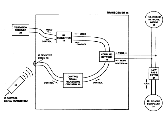
Figure 2 shows an arrangement of electronics for a
transceiver 15 designed to implement these functions.
This transceiver 15 is described in the following
paragraphs. The description discloses several optional
design variations.
An infrared sensitive diode 16 reacts to control
signals from an infrared control signal transmitter 23
to create the desired conversion to electrical energy.
. . ~ ,: .
The resulting signal is passed to the control signal
processing circuitry 17 which perform~ the translation ~ `~
to a frequency band above the telephone communications
band. The preferred embodiment of this circuitry is
shown in Figure 8 and described in detail later on. The
preferred embodiment calls for a transmission frequency
centered at 10.7 Mhz.
Signals generated by the control signal processing
circuitry 17 are passed to a coupling network 18. This
network feeds the control slgnals to the telephone
network wiring 26 and allows video signals to pass from
the wiring along the conductive path leading towards the ; -~
television receiver 22. The network also perform~ the
functions of matching the impedance of the video signal
path to that of the telephone wiring, blocking low~
frequency signals from the transceiver electronics,
blocking the diversion of video energy towards the
control signal processing circuitry 17, and blocking
higher harmonics of the control signal, but not the
fundamental of this signal from transmission to the
telephone wiring and from transmission along the
conductive path leading towards the television 22. -
The importance of these functions is described in
the following paragraphs. The detailed electronic
design of the preferred embodiment of this network is
~hown in Figure 7 and is described in detail later on.
. ., :;~::; .
37 :
.i........................................................................ ... ... ~.:: .
..... " ~,.
~ `
2 ~ 4 1
Impedance matching ensure8 an efficient transfer of
energy from the telephone wiring to the electronics of
the device. Just a8 in the cage of the video source
transceiver, the efficient trangfer of video energy
across this junction can be important in situations
where the signal energy i8 only marginally sufficient
to produce a high quality picture.
Blocking telephone and other low-frequency com- - h~
munications ~ignals from transmission to the electronics
of the transceiver prevents any interference with tho~e
signals and also prevents disturbance of the DC power
supplied to telephone devices. The blocking should be
such that it renders the functioning of these communica-
tions totally transparent to the connection and opera-
tion of the transceiver.
Blocking of video ~ignal energy from transmission
between the network 18 and the control signal processing i~
circuitry 17 is important because it prevent~ the
reduction of video signal energy by diversion along this ~ -
path.
Blocking the harmonics, but not the fundamental, of
the signal emerging from the control signal processing
circuitry 17 is important becauee some of the harmonics
may coincide with the frequencies used for tran~mission
o video. Because they will transmit to the television
22 A~ well as to the telephone wiring, these harmonics !'"~
can cause interference if they are of sufficient~ :i!''~ ~''/'
strength. No information is lost in this process
because the information in the harmonics of a signal is
completely redundant with the information in the ~ignal ;',".;',''!."',,~'"`,fundamental.
Unless the energy level of the control signal is
very high, there is no need to block the control signal
from transmi~sion across the network 18 towards the
televi~ion receiver 22. Thi~ i~ because television '~
38 ,`; ` ~;
, . .. , .. ,;,
.. ... ,, ,i ~
2 0 2 0 ~ 4 1 ~ ~
:. ,
receiver~ ignore energy outside the video channel to
which they are tuned unless that energy i9 at a very -~ -
high level. For example, televisions ignore energy at ~ -~
VHF channel 4 when they are tuned to VHF channel 5.
Problems also do not occur when the RF converter 19 is
required. In that event, the control ~ignal is shifted
in frequency along with the video signal, but it is
rejected by the television tuner for the same reasons as
before. Because the control signal signal cannot cause
interference or other harm to the television trans~
ceiver, the isolation circuitry described by the Robbins
patent, which blocks this intelligence from the televi~
sion, is unnecessary. ;
Signals passing along the path from the network
towards the television 22 encounter the RF converter 19.
As mentioned earlier, if a low VHF channel is used for
transmission, frequency conver~ion at the television end
is not necessary and signals can transmit directly from
the coupling network 18 to the television 22.
When channels below VHF 2 are used for transmis-
~ion, the RE converter 19 converts the video signal to
a channel that is tunable by ordinary televi~ions.
Because of potential interference problems, this channel
should be one that is not used by local broadcasting.
(Intererence could normally be avoided by connecting ;~
the tran8celver via a shielded coaxial cable. Many
older televi~ions, however, do not offer a shielded
input port, and many modern televisions exhibit slight
leakage from other available ports such a~ twin lead
port8.) !,. ' ''. "','''' '""'
Because the video source transceiver outputs video
signals at the transmission frequency, and this trans- ~ ,,,~.,~,,.!,
ceiver 15, inputs signals at that frequency, the two
units must obviously cooperate in their RF conversion
de~ign~. Throc Yyetc~a arc d1~c1o~cd hcrcin for coop-
. , ,., ;. .
202a~
eration between the RF converter8 of the disclosed
transceiver pair to transmit video at a channel below
VHF 2. Under each of the8e sy8tems, the sigral is
provided to the television 22 at one of two adjacent
broadcast channels, according to a ~witch set by the
user. In the U.S., this feature guarantees that the
requirement of providing a gignal at a channel not used
for local broadcasting ig fulfilled because, as
described earlier, the U.S. FCC has ensured that one of
two adjacent channels is always unused in a given
locality. A complete description of each of these
systems is presented in the next section.
The television transceiver connects to the tele~
phone wiring network 26 via a cord terminated with a
male RJ-ll plug. Just like the cord used for connection
of the video source transceiver, this cord contains a
low pass filter 24, which creates an isolated port that
allows connection of telephone equipment 25 without
loading down the video signal passing from the network
to the transceiver.
Unlike the cord connecting the video source
transceiver to the telephone wiring, it is not as
critical to supply this transceiver with a cord whose
conductors are twisted. That is because the level of
the video energy traversing the cord will be much lower,
and Wlll generate less radiation.
Because the television to which thi~ transceiver
connect~ may have another source of video signals
available, and because most televisions only have one
port for input of signals at VHF frequencies, it may
make sense to provide a switch that allows users to
connect both sources and quickly choose between them.
Because o the likelihood that no signals from the two
~ources contain energy at the same channel, any device
or component that perform~ thi~ function might also
2~29~
; ~
.-:
allow the addition of the two. Technology to achieve
these signal combination options is well known.
Such a component, not shown in the drawings, could
be an attachment that connected in series with the cable
connecting to the television. It might be more con- -~
venient, however, to include this component as part of
the transceiver. In that case, the transceiver would
simply include a coaxial port for input of ~ignals from ~ , `
a second source, and would be able to provide signals
from either source, or the combination of the two, to -~
the local television. Controls on the transceiver would
allow the user to choose the composition of the signal
provided to the television.
There is a possibility that, when receiving signals
from a video source located relatively close by, this
transceiver 15 may receive a signal whose energy level
is too high for the television to which it is connected.
In the event that the transceiver includes RF conversion
circuitry, the solution is to ensure that this circuitry
can manage high signal levels, and that a level within
the range of most television receivers is provided at
the output. When a low VHF channel is used for trans~
mission and RF conversion circuitry is not required, one :- `
solution is to provide attenuation circuitry, set ~-
automatically or manually, that reduces the energy of
the 8ignal to a level within the dynamic range of ~ ~ '
ordlnary televisions.
: ~, . :
Systems for RF Conversion to
Achieve Transmission below VHF Channel 2
As mentioned earlier, two RF conversion operations ~ `
are required in order to tran~mit the video signal `
across the wiring at a channel below VHF 2. At the
video source end, the transceiver must convert the
signal from the frequency at which it is supplied to a
41
, " .
i ~.,.: ,.
:` 2~
~2~ 8 4~ : ;
band between 6 Mhz and 54 Mhz. The transceiver con~
nected to the television must recover the signal from
within this band and convert it to a channel tunable by
ordinary television receivers. Three systems for ~ ~ -
cooperation between thege conversion operations are
described in the following paragraph~, along with their
respective advantages and disadvantages.
Under each of the 9ystems, the signal is provided
to the television 22 at one of two adjacent broadcast
channels, according to a switch set by the user. In the
U.S., this feature guarantees that the requirement of
providing a signal at a channel not used for local
broadcasting is fulfilled because, as described earlier,
the U.S. FCC has ensured that one of two adjacent
channels is always unused in a given locality.
The unusual nature of the conversion operations, ~ Z
combined with the novelty of u~ing these channels for a
consumer video application, or for any video application
other than the cable distribution function described
earlier, make the resulting electronics a new con~umer
electronic development. . ~
The system~ are summarized by the chart in Figure 1,'l,., ~ .
3. The precise electronic details of the various '
converters are not given because technology to achieve
the~e conversion~ is known, and would be within the ~ ;~
abillty of one of working skill in this field. l ~
Under the first system, the video source trans~
ceiver derives its signal from a low VHF port and i ~ ,
imparts a fixed downshift to produce one of two adjacent i- 'i'i,`
channels. Signals spanning 24 Mhz to 30 Mhz or 30 Mhz
to 36 Mhz, for example, are produced from VHF channels
3 or 4 by a ixed downshift of 36 Mhz. In the final
~tep o this system, the RF converter in the television
tran~ceiver impart~ an equivalent fixed upshift, restor-
lng th- ~lgnal to lt~ orlginal channel for dellvery to ~,~"
,,., " ~,
2~2~41
the television. The fixed down8hifts mean that the
choice of which of the two channels is actually used for
tran~mission is determined by the 8etting on the video
source that choose8 between VHF channel 3 or 4.
(There are a few video 80urces that supply signals
at VHF channels 2 or 3 instead of VHF channels 3 or 4.
To account for these sources, the ~hifting should be
designed to include bands covering at least 18 Mhz,
rather than 12 Mhz.)
The advantage of this sy~tem is that the versatili~
ty already supplied by the low VHF port of the video
source is used to ensure that the transmitted si~nal is
supplied to the television at an unused channel. This
enables the two RF converters to be designed to trans-
late by a fixed amount, reducing manufacturing costs.
The second system calls for the RF converter in the
video source transceiver to use the video signal from a
baseband port to modulate a carrier to either one of two
adjacent channels below VHF 2, according to a switch set
by the user. (It would ordinarily make sense, of
course, for the modulator to combine an audio signal, if
available, together with the video according to the NTSC
or an equivalent format, and then to modulate using this
combined signal.) In cooperation with this conversion,
the RF converter of the television transceiver again
upconverts by a ixed amount. If the modulation created
the channels spanning either 24 Mhz to 30 Mhz or 30 Mhz
to 36 Mhz, for example, an upshift of 36 Mhz would
produce VHF channels 3 or 4, an upshift of 52 Mhz would
produce VHF channels 5 or 6, and an upshift of 150 Mhz
would produce VHF channels 7 or 8.
The primary advantages of this design over the
fir~t are those advantages, described earlier, that
accrue to designs that derive signals from the baseband
port of the v1deo ~ourc-. Th-r- le al~c a convenl-nce
. :; .' ' . . ~:i
2~2~
in that inexpensive modulation ICs are available that
provide much of the circuitry necessary to build video
modulators with options for one of two carriers in the `
10 Mhz to 100 Mhz range. Finally, being able to choose -~
j adjacent VHF channel pair8 other than VHF channels 3 or
4 allows combination of the gignal pagged to the televi-
sion with signals from most common video sources.
Two variationg to the second sy~tem are now dis-
closed. In the first variation, the switch will be
automatically controlled. It will rely on circuitry
that samples the telephone line to detect the presence
of broadcast energy at either of the two channels used
to provide the signal to the televi~ion. (Broadcast
energy will be on the telephone line because it acts as
an antenna to some extent.) It will ~et the RF con-
verter in the video source transceiver to provide a `~
transmission frequency ~o as to ensure that the channel
ultimately presented to the television receiver will be
one unused for local broadcast.
In the second variation, the RF converter in the
video source transceiver will simultaneously provide the ; ,~
video signal at both of the two adjacent channel~ below ~ ` ;
VHF 2, 80 that when the television transceiver converts
the 12 Mhz band spanning these channels, it produces `~
signal8 at both of the two ad~acent tunable channels. ~`
The third system also calls for the video source
transceiver to derive its signal from the baseband port, ;~
but it includes an RF converter that has only a single '` ;
carrler which modulates the signal to a single fixed ;
channel that 18 used for transmission. The RF converter '''~'''"' ~"!'~'`'';~'i"'~
in the television transceiver then;performs either one l~ Z'"''~'"~
of two upward conversions, according to a switch set by `~
the user, resulting in one of two adjacent low VHF
channels. If the transmission channel spanned 24 Mhz to `!~ ~r
30 Mhz, for example, upshifts of 36 Mhz and 42 Mhz would
44 ~ ~`
,,".,~;,.. -..
. ` ~' ::
.
` '~' :'
.. .,.;,.. : .... . , : . .
^ 2~20~
produce VHF channels 3 and 4, and upshifts of 52 Mhz and
58 Mhz would produce VHF channels 5 and 6.
In a variation of this strategy the RF conversion
component of the television transceiver allows con~
tinuously variable manual tuning, ln place of two fixed
upshift conversions. This tuning must, of course, allow
the signal presented to the television to span two
consecutive channel~. The provi~ion of manual tuning
reduces the precision required for both converters,
resulting in a certain economy.
Like the second design, the two variations of the
third design al~o enjoy the advantage~ of baseband
input, and the advantage of being able to output ad-
~acent VHF frequencies other than VHF 3 and 4. The main
advantage over the second design i9 that the single
optimal sub-VHF 2 channel, in terms of radiation,
attenuation, interference from broadcast sources, legal
restrictions, and expense of conversion electronics, can
be chosen.
Because of these advantages, and because tran~mis-
sion over channels below VHF 2 aford~ reliability which
is of enormous importance in consumer products, this
third system is the preferred embodiment. Furthermore,
the fixed and not the variable tuning is preferred
becau~e of the importance of convenience in consumer
products. The preerred channel span~ from 24 to 30 Mhz
because there is a liberalization of U.S. FCC radiation
restrlctions below 30 Mhz, and becauQe the conversion
electronics are slightly more expensive when lower
requencies are u~ed. Finally, it is preerred to
pre~ent the ignal to the television at either VHF 5 or
6, because of the advantages o combining those channels
with broadcast signals or other video sources. (These
preerence~ may change as a result o data not currently
available to the inventors such as, speciically but not
~'~
2 ~ 2 ~
exclusively, information regarding the frequency,
strength, and location of RF sources throughout the U.S.
that may provide interference at channels below VHF 2.)
Two further variations to the third system are now
disclosed. In the first of these, the switch will be
automatically controlled. It will rely on circuitry to
detect the presence of broadcast energy, to set the RF
converter of television transceiver to convert the
transmitted video energy to the channel unused for local `~
broadcast. In the second variation, the RF converter of
the television transceiver will simultaneou~ly provide
the video signal at both of the two adjacent tunable
channels.
Description of the Spec1al Televi~ion Receiver ,
The transceiver pair disclosed above provides an i~
ability to view and control a video source at a remotely
located television. A ~ignificant economy can be ~a~,",~
achieved, however, if the function of the disclosed ```;;
television transceiver is internalized in the television
electronics.
A special television 30, shown in Figure, provides "~
such a combination. This television is intended to ,'Il,,`r,~
cooperate with the video source transceiver described
above. It comes equipped with a cord that includes a
low pas~ filter 32, similar to those used with the
tran~ceiver~ described earlier, for allowing telephone
eguipment 33 to share the same ~ack without loading down ~ }
vidoo ~ignals on the wiring. ~ `;
The television includes an IR sensitive diode 42, '
for converting infrared signals into electrical signals.
These signal~ are passed to the special control signal
processing circuitry 37 and the standard control signal
processing circuitry 41. The standard circuitry 41
reacts to these signals to execute control over televi- ~`
46
' ~', ','.`',,
' ' " ' ~'
2~2~841
sion operations in the ordinary manner. The i3pecial
control signal proces8ing circuitry 37 translates the
electrical version of the control ~ignals to a frequency
band above the highegt frequency used for ordinary
telephone communication8, and pa8~e8 them to the cou~
pling network 34.
The functions performed by the 8pecial control
signal processing circuitry 37 are the 8ame functions
performed by the control 8ignal processing component
included in the transceiver, described earlier, that
connect~ to the television. The preferred embodimen~
of the circuitry is also the same. This embodiment is
shown in Figure 8 and is de~cribed later on.
The coupling network 34 allows the control signal~
to pass to the telephone network wiring 31 and video
signals to transmit from the wiring along the conductive
path leading towards the RF converter 35. The network
34 also performs the important functions of matching the
impedance of the conductive path leading to the RF
converter to the impedance of the telephone wiring,
blocking low-frequency signals from the television
electronics, blocking the flow of video signals toward~
the ~pecial control signal processing circuitry 37, and
blocking harmonics of the control ~ignal, but not the
undamental o this signal from the telephone line and
the conductlve path leading towards the RF converter 35.
The functions performed by this network are the
~ame functions performed by the coupling network in-
cluded in the television transceiver described earlier.
An explanation o the importance of these functions was
included ln the description of that device. The pre-
ferred embodiment of the network u~ed here is also the
same. This embodiment is shown in Figure 7 and de3-
cribed later on.
~ '" """ '
47
''''''' ' ~ ',''`','~'. '
, ~'il'''''
` 202~341
,. ., ~i . ~ . ~,
Both the video and RF control signals pass from the
coupling network 34 to the RF converter 35. That
component will convert the ~ideo gignal to a channel
that is tunable by ordinary television tuning electro~
5nics. If a low VHF channel i8 used for transmission
across the wiring, however, ordinary television tuners
can tune to the transmitted 8ignal and this component is
not necessary.
Signals emerging from the RF converter 35 transmit ~-
10to the RF signal combiner 36. (If the RF converter 35
is not needed, signals flow di~ectly from the coupling
network 34 to this combiner.) The RF combiner 36 will
accept video signals from a local video source 43 if one
i8 available. It will add signals from the two sources, ~ j$.'.
15or will choose the signals from one source or the other
to pass along to the tuning section 38. The final
composition of the signals passed to the tuning section
38 will be set by manual controls on the television 30
or by infrared control signals received by the IR
20sensitive diode 42. i~
The RF converter 35 disclosed herein can cooperate
with the RF converter of the video source transceiver
using one of the three alternative systems, described
earlier, for cooperation between RF conversion com~
25ponents at the two ends of the communication path. The ;
RF converter 35 included in the television will simply
perorm the same functions as the RF converter of the i~
television transceiver described earlier, while the RF
converter in the video signal transceiver will perform
30the corresponding conversion.
A variation of the third ~ystem for cooperation ~`
between converters is now disclosed for the case of the
special television receiver 30. Under this variation,i~
the RF converter 35 demodulates the video signal it -~
receives, and in~ect~ that signal into the television at
48
. .
2 ~ 2 ~ ~ 4 1
the point where it ordinarily expects demodulated
signals. (The demodulated signal will not go into the
combiner in this case, eliminating the need for that
component. Signals from a local video qource 43 will
pass to the tuner without combination.) This variation
liberates the converter from providing a 8ignal at
either one of two adjacent channels, and might be less
expensive, overall, than the alternative.
Note that the RF converter 35 is not necessary if
the television tuner 38 can tune to qignalq below VHF
channel 2. This converter is offered as an alternative
to providing the television with a special tuner because
it may be less expensive to adapt the de~ign of an
ordinary television by adding thi0 simple component.
In the preferred embodiment, the video signal
tra~smits across the wiring at a frequency below VHF
channel 2, and the RF converter is required becauqe the
televiqion tuning qection 38 tunes in only the ordinari~
ly tunable channels. A channel below VHF 2 is pre-
ferred because of the decreased probability of picture
degradation, and the RF converter i8 preferred because
the inventors believe that it is less expensive to adapt
the design of an ordinary television by adding a con~
verter.
A tran~mission channel spanning 24 Mhz to 30 Mhz is
preferred, and it is preferred that the RF converter of
the television convert that channel upwards by either 52
Mhz or 58 Mhz to VHF channels 5 or 6, according to a
switch settlng on the television, or a command from the
lnfrared controller. This embodiment follows the pre-
ferred system, presented earlier, for coordlnation
between the RF converter of the video source transceiver
and the RF converter of the television transceiver. The
~ustifications used earlier also apply to this case.
The option of demodulating the video signal is not
2 9 ~ ~ ~ 4 ~
currently preferred because the expense of thi~ option
i 8 not clear. -~
Television 30 is novel in the following threè ~ -
respects. First, it connects to active telephone ~ -
networks, without causing interference, to derive video
signals, in addition to the video gignalq it derives ~ ~ -
from other sources. Secondly, in addition to detecting
infrared signals for the purpo~es of controlling tele~
vision functions, it converts these signals to electri~
cal RF energy, and passes them on to the telephone line
for controlling the video source in cooperation with
another device. Finally, it is able to tune to signals --
at channels below VHF 2.
When the television 30 cooperates with the video
source transceiver 1 described above, they allow the `~
user to watch and control a video source from a remote ~,,~.,.,,~,,/r,.,
location. To further increase the usefulness of this ~ ;
combination without significant extra cost, a unique
combination of this pair of devices with a special piece
of known technology is disclosed in the following two
paragraphs.
To control the video source from the area wherein
the special televi~ion receiver 30 i8 located, the
infrared transmitter unit that controls that source must
ordinarily be available at that location. This is not
always convenient, because this unit is obviously often
required at the location of the video source. If the 1:
television 30 is provided with it~ own infrared con- `;
troller, inclusion of the command set of the video
~ource controller as a subset of the available commands
significantly increases the convenience of the system
without significant extra cost.
Recently, infrared control units with large command
set~ that include those of many different controller~
have become available, as have other units that have the
: ~ .
~ ~
. :"''
2 ~ 2 ~
ability to learn the command sets from virtually any
other controller. The novel combination disclosed here
adds a similar universal controller together with the
disclosed cooperating television 30 and transceiver 1.
This will significantly increase the usefulness of that
pair of devices.
. ~ " ." ., ~,,,.., ~.
Systems for Avoidina Interference from Broadcast Sources
The signals transmitted by the devices disclosed
above travel from source to receiver via conduction
across telephone wiring. A potential problem of this
technique, described earlier, is that RF broadcast
energy from nearby sources can be received by the wiring
and interfere with the signal of interest. Under the
design option where the video signals transmit at a low
VHF channel, the devices provide signals at a channel
unused by any local service. This protection is not
available when the video signals transmit at frequencies
below VHF channel 2. The following factors, however,
make the possibility of interference unlikely~
a) The signal-to-noise ratio required for a quality
video picture, approximately 40dB, is relatively low.
Interfering signals must have energy levels within 40dB
of the signal of interest to visibly degrade a picture.
b) The signal of interest is conducted directly on
to the wiring. The interfering signal must be received
by the wiring acting as an antenna, a much less effi-
cient method of creating conductive energy.
c) The ability of the wiring to receive broadcast
ensrgy decreases with decreasing frequency.
d) The level of the signal of interest can be
boosted to reduce the potential of interference.
(Because of legal and technological constraints, how-
ever, there are limits to the level to which this energy
can be boosted.)
51
' . ., , 1 '" :, .
'."~ `'.'.' ~:
' .' ' ' ''~"; ~'
2 ~ 2 ~ 3 ~
Despite these factors, test8 have indicated that
interference can occur. Three methods for avoiding
interference problems are discussed below.
a) One can choose a frequency band that is less
likely to be used by many tran8mitter8 operating at high
power near residential area8. Thi8 8trategy requires a
survey of frequency allocation8 and broadcasting pat~
terns. Preliminary investigation by the inventors
revealed that amateur radio i8 allocated narrow bands at
7 Mhz, 14 Mhz, 21 Mhz, and 28 Mhz, conveniently leaving
gaps of 7 Mhz -- just right for video.
b) The video source transceiver can simultaneously
transmit its signal over two fre~uency bands, and the
signal that encounters less interference can be chosen,
at the television end, to provide the picture.
In the case of the cooperating transceiver pair,
the video source transceiver ~imultaneously transmits
the same signal over two diferent and non-overlapping
channels below VHF channel 2. The RF converter of the
transceiver that connects to the television chooses,
according to a manual control or an automatic process,
.. :, ,. ,:
to accept one of the two channels, converting the energy
within that channel to a tunable frequency unused for
local broadcast. (Circuitry to automatically choose the
less "noisy" channel would have to include means to
detect the presence of broadcast energy within each of
the two channels.)
In the ca~e of the special television that cooper-
ate~ wlth the video source transceiver and includes a
special RF converter, that converter performs the same
functions as the converter in the television trans-
ceiver. Under the design option wherein the televi~ion
tuner can tune directly to signals below VHF channel 2
(and a converter is not involved) the tuner simply tunes
to one channel or another.
52
~, ''; :'
, .
2a2~ ~ 4~
.~ . - . --
c) Because the information at the edges of an NTSC
video signal i9 redundant, these edges can be filtered
out before presentation to a television, removing any
interfering energy at those edges. Specifically, the
first 1.25 Mhz in an ordinary NTSC channel, known as the -
vestigial side band, can be filtered out before presen- ~;
tation to the television. This will reduce the video
bandwidth from 5.75 Mhz to 4.5 Mhz, reducing oppor- `~
tunities for interference. In the event that research
~hows that this causes ~ome degradation of picture
quality, the vestigial side band can be recreated free
from interference within the shielded televi~ion trans-
ceiver, u~ing known technique~
The upper .25 Mhz of the full 5.75 Mhz video signal
can also be filtered without significant reduction in
picture quality. Trimming this energy, however, will ~ :
remove the audio informatlon, which is located im- ~ ~
mediately above the video information. The solution is ~ -,`L,
to transmit the audio signal at a different frequency,
converting that signal to its proper place before
presentation to the television.
Systems for Simultaneous Transmission ~ r,'.
of a Second Video Signal ~ ?
A video source transceiver connecting a second ^~
~ource to the same residential wiring network obviously
ha~ to transmit its signal at a different frequency in
order to operate simultaneously with the first source. -~,
Ideally, this transceiver cooperates with the television -
transcelver unit without requiring any deslgn change~ to
that transceiver. That allows the most economlcal
deslgn for the primary transcelver pair, and still
allow~ expansion o the system to include a second `~'
source.
53 i
" ::
" ;.. ~':' ' '''', '
,... :. i'. `i
2 ~ 2 ~ g 4 1
If low VHF channel8 are used for transmi~sion,
design of the second video source transceiver is
straiqhtforward. That tran8ceiver 8imply transmits its
signal at one of a second pair of adjacent low VHF
channels. If, for example, the primary video source
transceiver uses VHF channel 5 or 6, the secondary
transceiver could use VHF channel 2 or 3. The
television transceiver described earlier will supply
both signals to the television receiver without any
design changes.
If the primary transmitter uses a channel below VHF
2, and the secondary transceiver use~ a low VHF channel,
a slight alteration in the design of the transceiver
that connects to the television is required. The
alteration calls for an extra signal path to the televi~
sion that bypasses the RF converter. That path includes
the unshifted low VHF signals which could be easily
combined with the signal that was converted up by the RF
converter. The channel generated by the RF converter,
of course, will have to be different from the channel
used for transmission of the second source.
Things are more complicated when both video signals
transmit at channels below VHF 2 because the television
transceiver must convert a second signal to a second
tunable channel that is not used for local broadcasting.
The ~hift in frequency required by the second signal,
moreover, may not necessarily be the same as that
required by the first signal. The largest problem,
however, may be finding an extra 6Mhz that is free from
broadcast source interference.
Extra transceiver~ that tran~mit video over the
same channel as the primary transceiver can be con-
nected, of course, as long as a viewer can disable all
but one of the resulting group of connected trans-
ceivers. In the following paragraphs, two designs are
54
-` 2 0 2 ~
.. ~ ........
disclosed for systems that allow9 a user to quickly,
conveniently, and remotely activate exactly one of ,~ ~
several connected video source transceivers transmitting ~ . -
at the same frequency. '~
The first design calls for the signal from all but .. ~.-
one of the transceivers to be blocked from transmission
on to the wiring. The blocking i8 accompli9hed by the ^~
touch tone switch 8 shown in Figure l. Thi9 switch
connects on the cord between the transceiver and the
telephone jack, and contains a low pass filter, or other `~
means that completely block signals above a frequency
that is below the frequencies used for video
transmission. It has two settings, one of which enables ~u~
the filter and the other which defeats it. The switch
reacts to the DTMF (dual tone multi frequency) touch ~ -
tones commonly created by telephones, allowing users to
conveniently select the active source from among the
several connected. Any loglcal command system will
suffice. The electronic details of this switch are not
shown because RF filters and touch tone controls are
well known.
The second design calls for each of the video ;
source transceivers that transmit at the same requency ..
to derive its AC power via powerline switches similar to
those bullt by the X-10 Corporation. These switches
connoct between power cords and AC outlets. They detect
hlgh requency control signals fed onto the wiring by a
remote device, and respond by blocking or enabling power
to pa~ along the power cord to the connected electrical ,!,'~ ","~
device. This allows one to remotely control the AC
power to any device in a residence via control ~ignals ; ~
sent through the AC wiring. Thus, a user could con- `~ ;,
veniently select one o many sources sharing a transmis- ~ a~
sion requency by activiating the AC power for the ;~
transceiver o that source and none of the others. i ,~
2 0 2 ~ $ ~
. .. .
.. .-
Because the first design u8e8 ordinary touch tone
telephones to the send signal8 that e5tablish the
identity of the active tran8ceiver, it is preferred over
the second design, which require8 8pecial transmitters :
to send those signal3.
Description of the Adaptor for ~-~
Central Telephone Switchin~ Devices
As mentioned in the introduction, a reliable
conductive path is not alway8 available in residences
where each jack is wired directly to a central elec~
tronic interface unit that connects to the public
telephone system. Because of the topology of these
networks, potential conductive paths from one jack to
another will always traverse this unit, where their
continuity is likely to be broken.
To allow the disclosed devices to operate on such
a network, an inexpensive adaptor 52 is disclosed. This -
adaptor is shown in Figure 5.
Normally, the wiring leading from the jack 50 in
the first area 51 would connect to the port 56 on the
electronic switching unit 58 dedicated to the first
area. Similarly, the wiring leading from the ~ack 53 in
the second area 54 would connect to the port 57 on the
unlt dedicated to the second area. - :~
The adaptor 58 reroutes these connections through
a palr of low pass filters 59 and 60. These block the
, . .. .~.: ~: -
transmi~ion of high frequency signals away from the ;~
swltching unit, eliminating attenuation. The filtering ~ ,,
can be achieved by the same pair of inductors disclosed
earlier that achieve low pass filtering of any telephone
eguipment that shares a ~ack with either of the two
cooperating tran~ceivers.
The high pass filter 61 connects the paths leading
from the fir~t area 51 to the second area 54 at high ~;~
56
'''" '~"' ~'~'"
' ' ~': : '
,~
2 ~ 2 ~ ~ 4 1
frequencie~, completing the conductive path for video
and control signals between the associated jacks.
Transmission of low-frequency energy across this path i~
blocked, maintaining separation of the telephone and
other low-frequency communication between each jack and
the switching unit. In the preferred embodiment, the
high pass filtering is achieved by a pair of lOOpF
capacitor~, connected as shown.
The problem of inade~ ate video signal energy in
the area where the television i8 located was described
earlier. Because the disclosed adaptor offers access to
the signal near the midpoint of its transmission path,
it offers a new solution to this problem. The solution,
not shown in the drawings, call~ for an amplifier to
accompany the adaptor. A path leading from a video
source could be passed through thi~ amplifier just
before connection to the adaptor. In this way, part of
the total amplification required could be imparted at
the video source transceiver, and the other part at the
switching unit. This would reduce the peak signal power
at any point for a given level of total amplification,
thus reducing the maximum level of radiation.
For systems that also transmit control signals, a
bypass around the amplifier for transmission of these
signals would have to be made. The bypa~s would simply
be a conductive path around the amplifier including a
filtor to block video signals. Similarly, the input to
the amplifier would require a filter to block out
control signals.
Because the technology disclosed herein is not
limited to residential networks, and because "star"
wiring configurations including a central switching unit
are very common among telephone networks installed in
commercial buildings, including but not limited to
offices and hotels, the disclosed adaptor has the
57
, ';' .,
-., :., . .:
: . ~, ~.' ..'..'.
, .:: .:
202~4~ :
important function of enabling tho5e installations to - -
benefit from this video transmi8sion technique. - --
Details of the Couplina Network Circuitry
The earlier descriptiong of the cooperating trans~
ceivers referred to coupling network circuitry in ~ -
functional terms. The preferred embodiment of this
circuitry is now presented in detail.
Figure 6 shows the preferred embodiment of the
coupling network of the video source transceiver. The
principal element of this network is a transformer wound
on a toroid core 71. There are three isolated windings
corresponding to the ports leading to the telephone ~b~ ~`t~
network wiring 72, the video signal amplifier 73, and
the control ~ignal processing circuitry 74. The special
winding method shown for the phone line port serves to
maximize its balance.
The low pass filter 75 on the port leading to the
control signal processing circuitry 74 blocks signals
above the frequency used for control signals. This ~ ;
blocks the video energy, preventing that energy from ;~
disturbing the processing of the control signal~, and
prevents loading of video signals on the telephone line. i~
There are different numbers of windings on the
toroid core for the three different ports. (The number
of winding~ shown are only for purposes of illustra~
tion.) The turns ratios determine the impedance match~
ing between the telephone port and the other two ports. ~ ~ '
Diforent ratios are needed because the video port and ;``
the control signal port have different impedances ~t
different freauencies. ;-~
The impedance matching for video signals is
governed strictly by the turns ratio between the tele-
phone port and the video port. It is independent of the ~7
58 ~
- ` 2 ~ 2 ~
windings on the IR port because the filter 75 prevents
video enerqy from flowing towards that port.
The capacitor 77 serve8 a8 a high pags filter to
block and present a high impedance to DC and low-fre~
quency energy, preventing any di8turbance of ordinary
telephone communications at tho8e frequencies.
Figure 7 shows the preferred embodiment of the
coupling network of the televi8ion transceiver. The
principal element of this network i8 again a transformer
wound on a toroid core 80. There are three isolated
windings corresponding to the ports leading to the
telephone line 81, the television receiver 82, and the
control signal processing circuitry 83. The special
winding method for the telephone line shown earlier is
not necessary because maximum balance i~ not a~ impor~
tant due to the lower energy level of the video signal~
at this end.
The low pass filter 84 on the control signal port
passes the 10.7 Mhz signal but block~ harmonics of 10.7
Mhz. These harmonics, whose intelligence is redundant
with the intelligence in the fundamental, could poten-
tially interfere with the video signals. The resulting
control signal passes on to both the telephone line and
to the television. To prevent loading down the video
signal, the filter 84 also blocks video signals from the
control signal port.
There are different numbers of windings on the
toroid core 80 for the three ports. (The number of
windings shown are only for purposes of illustration.)
The turns ratios determine impedance matching. Because
the level of the control signal is high enough to easily
survive the influence of any impedance mismatch, the
impedance of the ports need only be properly matched at
video frequencie~, and only between the telephone line
port and the video port.
59
.: ~. . .
,. ~ .. ,: .
. ... :,
.: .-'', " ~ ~
, : .
; ,' ,. ~,,'~,T~
- 2~2~8~.t
The capacitor 85 serves as a high pass filter to
block DC and low-frequency energy and prevent any
disturbance with ordinary telephone communications at
those frequencies.
It should be understood that various changes and
modifications to the preferred embodiment of the cou~
pling network described above will be apparent to those
skilled in the art. For example, other winding con-
figurations are possible, including but not limited to
broadband multifilar configurations. These and other
changes can be made without departing from the spirit
and scope of the invention.
Details of the Control Sianal Processina Circuitry
The earlier descriptions of the cooperating trans-
ceivers referred to control signal processing circuitry
in functional terms. The preferred embodiment of this
circuitry is now presented in detail.
Figure 8 shows the details of the control signal
processing circuitry in the television transceiver that
detects infrared signals, and translates them to RF
energy. This circuitry consists of a photodiode lOl, a
high-gain amplifier stage 102, a thresholded zero
crossing detector 103, and a gated oscillator 104.
These elements are arranged to produce a modulated RF
carrier who~e envelope is a replica of the infrared
~ignal waveform.
The RF carrier is coupled to the telephone line
through the coupling network 105. The coupling network
~hown ln Figure ~ is designed only to feed control
signals on to the network. The coupling network of the
preferred embodiment, which is designed to include
recovery of video signals from the wiring, is shown in
Figure 7 and wa~ described earlier.
'
;~
232~4~
Photodiode 101 functions a~ a current source with ~1
current proportional to the intensity of incident light - .
within its spectral passband. This photocurrent is
converted to a voltage by resistor 110 and amplified by
5integrated circuit 111. Capacitors 112 and 113 reduce :~
the low frequency gain of the amplifier stage to render
the receiver insensitive to ambient light sources, ~uch ;~
as sunlight or AC powered interior lighting with a
nominal 120 Hz flicker rate. Transistor 114 buffers and i -~
level-shifts the output of the amplifier, and passes the
signal to the zero crossing detector section 103.
The output of the detector section 103 is a bi~
level waveform that corresponds to the received infrared
signal. This output is high when the input signal ;~
15exceeds its long term average, and low otherwise. Noise ~`-
effects are suppressed by disabling the bi-level signal ;~
except when the excursions of the input signal exceed a
fixed threshold. The bi-level waveform is fed to the
oscillation section to enable or disable the RF carrier,
thu~ generating the desired AM signal at an RF freguen~
cy.
The output of comparator 122 is set high when the ` ` ~
optical flux is greater than the long term average, ~;
which is formed using an averaging time of 100 msec, as l ~1
25determined by capacitor 127. - i ,
The noi~e condition is detected by comparator 123.
It set~ its output low when the input signal is a fixed
amount greater than the long term average. This thres- ~- i
hold 1~ set 80 that noise will not cause it to be ~ ~
30exceeded. The threshold may be changed as desired by ~;
altering the ratio of resistors 116 and 117 to provide
diferent level~ of noise suppression.
Capacitor 126 causes a low output from comparator
123 to remain low for a fixed perlod. Comparator 124
35inverts this output, and comparator 125 is used to merge
61
; '` '~
:,` . .-.~"
2 ~
that output with the the output from comparator 122. In
this manner, the output exit8 to the oscillator section
without interruption when a genuine signal is present,
and dies off quickly when the signal disappears.
In the oscillator section, tran8istor 118 is wired
as a Colpitts oscillator with frequency determined
primarily by capacitor ll9 and variable inductor 120.
In the preferred embodiment, this frequency is selected
to be 10.7 Mhz because of the good availability of
tuning components at this frequency. When the oscil~
lator is disabled by comparator 125, an idle current of
several milliamps is drawn through the inductor and
resistor 121. This idle current provides rapid turn-
on of the oscillator within a microsecond when the
oscillator is activated by comparator 125 going to a
high impedance state at its open-collector output.
Figure 9 shows the control signal processing
circuitry in the video source transceiver that uses
control ~ignals recovered from the network to recreate
the infrared pattern detected by the television trans-
ceiver. The circuitry consists of an RF amplifier/
detector 131, threshold/driver circuitry 132, and an
output LED 142.
~:
The control signals are recovered from the tele~
phone line by the telephone coupling network 130. The
coupling network shown in Figure 9 is designed only to
recover control signals from the network. The coupling
network of the preferred embodiment, which i8 designed
to include transmission of video signals onto the
network, is Ehown in Figure 6 and was described earlier.
Signals recovered from the network pass through RF
filter 133. This filter, which is part of the coupling ~; ,~',,r'~
network, is a ceramic filter with bandpass centered at
10.7 Mhz and a bandwidth of 280 khz. This matches the
62
"' ; ''``'"''"'"''
. ~: " ", '
2 ~ 2 ~
characteri~Ztics of the RF signal8 generated by the
infrared signal proces~ing circuitry described above.
The RF amplifier/detector 131 amplifies and en~
velope detects the signals that pass through the filter.
5 In the preferred embodiment, this function is performed
by an integrated circuit 134 of type 3089, which is
commonly used as an IF amplifier in commercial FM
radios. The detected output is logarithmically related
to the amplitude of the RF input signal.
The detected output is buffered by Darlington
transistor 140. Comparator 141 provides threshold
detection by comparing the instantaneous envelope of the
detected signal to the peak envelope of the detected
signal. The comparator turns on LED 142 whenever the
envelope exceeds a fixed percentage of the peak.
Resistors 143 and 144 set the threshold of the transmit-
ter; the LED will not be driven on unless a minimum
signal level at the input of the integrated circuit 134
i~ exceeded.
While the foregoing ha~ been provided with refer-
ence to one or more preferred embodiments, various
changes within the spirit of the invention will be
apparent to tho~e of working skill in thi~ technical
field. Thus, the invention should be con~idered as
llmited only by the scope of the appended claims.
~`",'~'~,
','~ ', ' ,''~
.'.Z',I"
63 ~ -
.... ... . .