Note: Descriptions are shown in the official language in which they were submitted.
IMPROVED SAFETY UNIT ACTUATING DEVICE
Background of the Invention
The present invention relates generally to devices that are
mounted on vehicles to operate safety units associated with the
vehicle, such as crossing arms, stop signs and the like which are
mounted on school buses for selective movement outwardly
therefrom to form barriers or warning devices.
It is, of course, well known that children, particularly
young children, who are transported in school buses are
vulnerable to accidents involving the school bus or the children
themselves during the time they are leaving or approaching the
school bus, and it is therefore common practice to provide school
buses with safety units that are designed to reduce the risk of
such accidents.
One familiar safety unit tha~ is almost universally found
on school buses is the octagonal stop sign that is usually
mounted on one side of the school bus, and that is movable from
a normal retracted position along the side of the school bus to
an extended position projecting outwardly from the side of the
bus to warn other motorists that chiIdren are leaving or
approaching the school bus so that such motorists can stop all
movement of their vehicles until the children have safely boarded
the bus or cleared the area after leaving the bus. Typical stop
sign safety devices of this type are disclosed in Latta U.S.
Patent Nos. 4,138,668; 4,339,744; and 4,559,518.
Another familiar safety unit frequently found on school
~3Q l \~buses is a crossing arm that is usually mounted on the front
C5'`~ bumper of the school bus and that is arranged for pivotal
' ~
movement from a first retracted or passive position, at which the
generally lengthy crossing arm extends along and adjacent the
bumper, to a second active position at which it extends outwardly
and generally perpendicular with respect to the bumper, thereby
providing a barrier that encourages children to walk in a path
well away from the front bumper of the school bus so that the
driver of the school bus can readily see the children and avoid
moving the bus until they have cleared the area in front of the
bus. The construction and operation of crossing arms of this
type are disclosed in greater detail in Latta U.S. Patent No.
4,559,518, Wicker U.S. Patent No. 4,697,541 and Runkle U.S.
Patent No. 3, 153,398.
As discussed in the above-identified prior art patents, the
actuating devices for moving the safety units between their
retracted and deployed or extended positions may be vacuum (or
air) operated, or they may be electrically operated, and such
actuating devices are generally designed to stop movement only
at the retracted and deployed positions. However, since the
safety units, at their deployed positions, are extending
outwardly and generally perpendicularly from the school bus, they
invite the attention of children, and others, and offer a
tempting target to be pushed away from such extended position by
the children passing by the extended safety unit. Also, even in
their retracted positions, the safety units present a temptation
for children to pull them outwardly from such retracted position.
Obviously, if the actuating device for the safety unit included
only a rigid drive connection between the operating mechanism
(e.g. electric motor) and the movable safety unit, any such
3 202~q I Q
manual pushing or pulling force applied directly to the safety
unit could damage or even destroy the operating mechanism of the
actuating device.
To overcome this problem, it is now common practice to
' 5 provide safety unit actuating devices with a double-acting hinge
construction of the type generally disclosed in Latta U.S. Patent
No. 4,138,668 that includes relatively heavy coil springs that
j are arranged to resist any manual movement of the safety unit
from its set position, and, if a manual force is applied to tho
iO safety unit of sufficient magnitude to move the safety unit from
its set position, the springs will return the safety unit to its
original set position. Also, there is another known hinge device
that accomplishes generally the same function as the aforesaid
double-acting hinge by utilizing a combination of a biasing
spring and cam surface arrangement, whereby manual movement of
the safety unit causes the cam to move along a cam surface until
the safety unit is released, and the spring then returns the
safety unit to its extended position. The cam surface has a
configuration such that if the safety units moved within a
predetermined range from its extended position, it will return
to its extended position, but if it is moved beyond such
predetermined range and toward it retracted position, it will be
moved by the spring to the retracted position rather than
returned to the extended position. An example of this type of
hinge device is disclosed in U.S. Patent No. 4,766,413.
More recently in my copending Canadian Patent Application
No.2003oo3-s~ filed January 17, 1990, an improved actuating device
is disclosed which includes, in lieu of the aforesaid hinges, a
~ J~
slip clutch between the drive motor and the safety unit support
that causes the safety unit to normally be positively moved from
its retracted position to its deployed position, or vice versa,
and which also permits relative movement of the safety unit with
respect to the drive though when a predetermined force is applied
to the safety unit, such as the manual pushing and pulling
thereof by a child. Several control circuits are also provided
for returning the safety unit to its retracted or deployed
position from which it has been moved.
In all of the aforesaid devices, the safety unit (e.g.
crossing arm) is driven by an actuator, which may be an electric,
air, or vacuum motor, that first moves the safety unit from a
stationary retracted position adjacent the bus to a stationary
deployed position, at which it remains for a period of time until
its intended purpose has been accomplished (e.g. all the children
have passed safely across the extended crossing area at the front
of the bus). Then, the drive motor is reactivated to return the
safety unit to its retracted position where it remains until it
is needed again. With regard to crossing arms located on the
front bumper of the bus, it is generally desirable to actuate the
drive motor when the door of the school kus is first opened,
whereby the crossing arm will be moved to its stationary extended
position prior to the children leaving the bus, or at least prior
to the time when they have left the bus and reached the front of
the bus.
While such extended stationary crossing arms provide an
effective barrier that normally forces children to follow a path
of movement that keeps them within the sight of the operator of
the school bus, it is still possible that a child leaving the bus
may decide to walk along and immediately adjacent the front
bumper of the school bus and then stop when he or she reaches the
point at which the innermost end of the crossing arm is joined
to the bumper of the school bus, which would defeat the purpose
of the crossing arm since the child would be located directly in
front of the bus and possibly out of the line of vision of the
school bus operator seated in the bus. Obviously, under these
circumstances a serious accident could occur if the operator
retracts the crossing arm and drives the bus forward.
The present invention provides a safety unit actuating
device which is designed to substantially eliminate the
likelihood of such a serious accident occurring and to provide
additional desirable safety features not found in known devices
of this type.
~ummary of the Invention
The present invention relates to an actuating device for
operating a safety unit such as a crossing arm or the like which
is mounted on a vehicle, such as a school bus, and normally
carried at a retracted position adjacent the vehicle. The
actuating device includes an arrangement for mounting the
actuating device on the vehicle and a motor having an output
drive. A support is provided for supporting the safety unit
(e.g. crossing arm) for movement with respect to the vehicle, and
this support is arranged to normally dispose the safety unit at
a retracted position, and is pivotally movable by the motor to
move the safety unit away from its retracted position and
through a predetermined path of movement. A control system is
..:.
- f~ f~ f~ fj~ J~
provide which operates the motor to selectively move the support
continuously back and forth in a sweeping movement through the
aforesaid predetermined path of movement so that the safety unit
provides a continuously moving barrier within a predetermined
area adjacent the vehicle.
In one preferred embodiment of the present invention, the
control system includes limit switches or similar means for
determining the outer limits of the predetermined path of
movement, and these limit switches or limit means are selectively
adjustable to vary at least one of the outer limits of movement
so that the path of movement through which the safety unit moves
can be selectively varied. Preferably, the predetermined path
of movement is an arcuate path having an included angle between
its outer limits that is approximately 165.
The present invention also includes a unique feature by
which a warning signal is generated whenever the presence of an
object located in the path of movement of the safety unit is
detected. Thus, if a child should inadvertently move into the
path of movement of the crossing arm rather than going around the
crossing arm, the operator of the school bus will be notified of
such condition by virtue of the warning signal generated in
accordance with the present invention, and corrective steps can
be taken by the operator to assure the safety of the child.
Preferably, the output from the motor is connected to the support
means for the safety unit through a slip clutch that permits the
output drive to continue its movement even when the movement of
the safety unit is stopped or slowed because it has contacted a
child or other object in its path of movement. Also, in the
,-, , " ,., ". 1., " " ,, "~" ~", ~, . ~ " , .
,sj ~
preferred embodiment, the motor is an electric motor, and the
warning apparatus includes a sensor for sensing a predetermined
increase in electrical current supplied to the motor which will
occur whenever the normal movement of the support means through
its predetermined path of movement is stopped or slowed, and a
signal is generated each time the sensor senses the predetermined
increase in electrical current.
In accordance with another feature of the present invention,
two actuating devices may be mounted adjacent one another on the
vehicle, such as on the front bumper, and these two units are
then operated so that the safety units are moved in a
coordinating manner to provide an effective moving barrier over
a substantial area adjacent the school bus. In another
embodiment of the present invention, the safety unit may be
located adjacent the wheel of the school bus, and is movable from
a retracted position disposed beneath the bus through a
predetermined path of movement adjacent the wheel of the bus.
Finally, in another embodiment of the present invention, an
extendable line, which may be made of resilient material or
carried in a housing so that the variable length can be withdrawn
therefrom, is used in conjunction with the moving safety unit to
form an additional barrier. In a preferred embodiment, this
extendable line is anchored to the bus or vehicle, and is also
engaged by the extending end of the safety unit so that as the
safety unit is moving through its predetermined path of movement,
the extendable line will extend between the end portion of the
safety unit and the school bus to provide a barrier in addition
to the barrier provided by the safety unit itself.
,",, " ; ", , " ~ , " ~ ",~ -, . -
; ,. . . . . . . ...... . . , . .. ... ,., , , ,~ , ..... ... . . ..
srief DeQcription of ths Drawing~
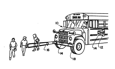
Fig. 1 illustrates a school bus employing a crossing arm
safety unit including the improved actuating device of the
present invention;
Fig. 2 is a detailed perspective view illustrating the
housing and mounting arrangement for the pivotal support for the
safety unit, and the drive for moving the pivotal arrangement,
the electrical components being omitted from this view for
clarity of illustration;
Fig. 3 is a detailed view, partly in section, illustrating
the clutch arrangement of the present invention;
Fig. 4 is a detailed view illustrating the limit switches
forming part of the control circuit of the present invention;
Figs. S and 5A-5E illustrate diagrammatically the control
circuit operation of the present invention;
Fig. 6 is a plan view of the front end of a school bus
showing one embodiment of the safety unit arrangement of the
present invention;
Fig. 7 is a plan view of the front end of a school bus
showing another embodiment of the present invention;
Fig. 8 is a plan view of the front end of a school bus
illustrating still another embodiment of the present invention;
Fig. 9 is a plan view of the front end of a school bus
illustrating yet another embodiment of the present invention; and
Fig. 10 is a perspective view of a portion of a side of a
school bus illustrating still another embodiment of the present
invention.
Description of the Preferred Embodiments
9 2021~9 ~
Looking now in greater detail at the accompa~ying drawings,
Figs. 1-4 illustrate the mechanical portions of the preferred
; embodiment of the present invention which are quite similar tothe mechanical portions disclosed in the aforesaid pending
Patent Application Serial No. 2008003-5.
A typical school bus lO is shown in Fig. 1 as having two
types of safety units associated with the bus, namely a stop
sign 12 carried at the side of the bus in a housing 14 for
movement between a retracted position along side the bus and an
extended position at which it extends outwardly from the side of
the bus in a generally perpendicular relation thereto, and a
crossing arm 16 carried in a housing 14 attached to the front
bumper 18 of the bus, the crossing arm 16 being movable between
a retracted position at which it extends along the length of the
bumper 18 as shown in dotted lines in Fig. 1, and an extended
position at which it extends generally perpendicular to the
bumper 18 as shown in full lines in Fig. 1. The stop sign 12
performs the well-known function of alerting motorists in the
vicinity of the school bus that the school bus has stopped to
load or unload children, and the crossing arm 16 is moved in a
predetermined path of movement when the school bus has stopped
to load or unload children, whereby the children are required to
walk around the crossing arm 16 in full view of the driver of the
school bus so as to avoid any accidental movement of the school
bus when a child is located in front of the school bus.
Since the stop sign 12 and the crossing arm 16 may be
operated by substantially similar operating arrangements, only
one such arrangement is shown and described in Figs. 1-4, but it
,__ s f ,' ~
will be understood that such arrangement could be used with
either the stop sign 12 or the crossing arm 16, or both. The
housing 14 includes a generally U-shaped support 20 for mounting
the actuating device and safety unit on a vehicle such as school
bus 10 using bolts 22. A pivot member 24 is mounted to the
support 20 by a first pivot shaft assembly 26 that includes, at
one end thereof, a stub shaft 28 that permits pivotal movement
of the pivot member 24 with respect to the support 20. The stub
shaft 28 is an extended portion of a cam shaft 30 located within
the housing 14 and which will be described in greater detail
below. One end of the pivot member 24 is mounted on the
support 20 by a second pivot shaft assembly 32 extending through
the flange of the support 20 with its extending end being engaged
by the first clutch component 36 of a friction clutch
arrangement 38 as best seen in Fig. 3. The clutch assembly 38
also includes a second clutch component 40, the first and second
clutch components 36 and 40 being generally cylindrical in shape
and resting against one another at surfaces 44 and 42,
respectively. A sleeve member 46 surrounds both of the clutch
components 36 and 40 so as to be in contact with the external
cylindrical surfaces of both such components, and the sleeve
member 46 is maintained in contact with such exterior surfaces
by a plurality of biasing elements 50 which are preferably in the
form of steel rings expanded beyond their normal diameter so as
to exert a biasing force against the sleeve member 46 and
maintain it in frictional engagement with the exterior surfaces
of the clutch components 36 and 40. The second clutch component
40 is generally fixed to a drive shaft 52 extending from a gear
~h ~
reduction unit 54 being selected to reduce the output revolutions
of the motor 56 to a predetermined speed selected for use with
the present invention. The electric motor 56 and the gear
reduction unit 54 are preferably carried on a bracket 58 secured
to the support 20, and the drive shaft 52 extends through the
bracket 58 and is rotatable therein. Another similar bracket 60
is carried by the support 20, and the previously described stub
shaft 28 extends through the horizontal flange of the bracket 60
to an integral connection with the aforesaid cam shaft 30, and
a first limit switch 62, a second limit switch 64, and a third
limit switch 66 are mounted at one surface of the bracket 60 for
selective engagement with the cam shaft 30. the cam shaft 30 is
specially formed with camming surfaces 30' and longitudinal
grooves 30'' which are generally shown in Fig. 4, and which are
more specifically shown in Figs. 5A-5E. Each of the limit
switches 62-66 includes a switch element 68 extending therefrom
(see Fig. 4) which is controlled by the cam surfaces 30' and the
grooves 30 " to move the switches between open and closed
positions as will be described in greater detail below.
When the electric motor 56 is operated by the control
circuit, which will be described in greater detail presently, the
output from the electric motor 56 is mechanically transmitted
through the gear reduction unit 54 to the output drive shaft 52
which is connected to the second clutch element 40 to rotate the
same. In normal operation, the sleeve 46 and the biasing
elements 50 maintain the first and second clutch components 36
and 40 in a positive driving relationship, and the output from
drive shaft 52 is transmitted through the friction clutch 38 to
:
12
the pivot shaft 34 and the second pivot assembly 32 to cause
pivotal movement of the pivot member 24 and the crossing arm
safety unit 16 supported thereby. If, however, a child or some
other object should be in the path of movement of the crossing
arm 16 so as to stop or significantly slow such movement, the
friction clutch 38 will permit relative movement of the first and
second clutch components 36 and 40 with respect to the sleeve 46,
and at the surfaces 42 and 44, whereby the rotation of the drive
shaft 52 can continue without burning out or damaging the
electric motor 56, and the crossing arm 16 is not forced against
the child or other object in its path. Further details of the
friction clutch arrangement, and the advantages thereof, may be
obtained from the aforesaid copending U.S. Patent Application
Serial No. 303,849.
The control circuit, which is contained in the housing 14,
is illustrated in Fig. 5 in conjunction with the electric
motor 56, and this control circuit will be explained ln
conjunction with Figs. 5A-5E which illustrate diagrammatically
the various positions of the cam shaft 30 and the limit
switches 62, 64, and 66. The control circuit includes an
ignition switch 70, a door switch 72 which is normally open and
which closes when the door of the school bus is opened by the
operator, a double-pole double-throw switch 74, a green indicator
lamp 76, a red warning lamp 78 and a warning buzzer 80, all of
which are located within the cab of the school bus which is
indicated diagrammatically by the dotted line 82. As shown in
.
Fig.5, the control circuit is in the condition that it would
normally be during the time the bus is not discharging or
receiving children, and the crossing arm 16 is carried in its
normal retracted position, such as extending along and adjacent
to the front bumper of the bus. In this condition, a circuit is
completed through the ignition switch 70, the double-pole double-
throw toggle switch 74, the green indicator light 76, limitswitch 66 and the normally closed contact 84' of relay 84 to
ground. The green light is illuminated in this condition of the
circuit to indicate to the operator that the circuit is energized
but the crossing arm or other safety unit is in its retracted
position.
If the bus stops to discharge or receive children, the
operator opens the school bus door 10' which closes the door
switch 72 and completes a circuit from the ignition switch 70
through relays 84 and 86, through toggle switch 74 and closed
door switch 72. Since the relays 84 and 86 are now energized,
a further circuit is completed from the ignition switch through
the now closed contact 86', the normally closed contact 88' of
relay 88, the electric motor 56, the normally closed contact 90'
of relay 90, the now closed contact 84 " to ground. Since the
motor ~6 is energized to rotate in one direction in this
condition of the control circuit, it will begin to pivot the
crossing arm 16 through the friction clutch 38 in the manner
described above, and the crossing arm will begin its pivotal
movement from its retracted position and away from the bus. As
soon as this movement begins, the cam shaft 30 will begin to
rotate and will move from its position shown in Fig. 5A to its
position shown in 5B, which are identical except that the limit
switch 66 leaves a slot in the cam shaft so that the limit switch
66 in Fig. 5 moves to its lowermost contact, thereby opening the
above-described circuit through the green light 76. Since the
green light is no longer illuminated, the operator is made aware
that the crossing arm has moved away from its normal retracted
position. The control circuit will remain in this condition, and
the crossing arm will continue its outward movement away from the
school bus bumper, until the cam shaft 30 is rotated to the
position shown in Fig. 5C, whereupon the first limit switch 62
enters a groove 30 " in the cam shaft 30 and is closed. When
limit switch 62 closes, a circuit is completed through ignition
switch 70, still closed contact 86', limit switch 62, relays 88,
90 and 92, still closed contact 84'', to ground. The
energization of relays 88, 90, and 92 results in a circuit being
completed through ignition switch 70, still closed contact 86',
now closed contact 88 ", motor 56, now closed contact gO", still
closed contact 84 " to ground. This circuit also completes a
circuit through the motor 56, but in the reverse direction to
that described above, whereby the crossing arm 16 will reverse
its direction of movement and begin moving back towards its
retracted position. It will be noted that when the motor 56
reverses, the direction of movement of the cam shaft 30 also
reverses, and the limit switch 62 (which had just closed when it
entered the groove 30" in cam shaft 30 as described above) will
immediately open again, so that the limit switch 62 only remains
closed momentarily to energize the relays 88, 90, and 92.
However, it will also be noted that even after limit switch 62
has immediately reopened, the relays 88, 90 and 92 are
nevertheless maintained in their energized condition by a circuit
~2~
that is completed through ignition switch 70, still closed
contact 86', limit switch 64, now closed contact 92', relays 88,
90, 92, and still closed contact 84 ", to ground.
The crossing arm will continue its return movement toward
its retracted position until the cam shaft 30 reachss the
position shown in Fig. 5D, and normally closed limit switch 64
is moved to its open position, thereby opening the above-
described circuit through relays 88, 90, and 92, whereupon the
contacts for these three relays return to their normal condition
which is shown in Fig. 5. In this condition, the direction of
rotation of the motor 56 is again reversed by a circuit completed
through ignition switch 70, still closed contact 86'', normally
closed contact 88', motor 56, normally closed contact 90', still
closed contact 84 ", to ground. Thus, the direction of rotation
of the motor 56 is now such that the pivotal movement of the
crossing arm is again reversed, and it begins to move in a
direction away from its retracted position, and it will continue -~
to move in that direction until limit switch 62 enters the groove
30 " in cam shaft 30 as shown in Fig. 5C and is momentarily
closed as described above, whereupon the circuit through the
motor 56 is again reversed in the same manner as that described
above. Thus, it will be apparent that until the condition of the
circuit is changed by the operator, the crossing arm 16 will move
continuously through a back and forth or oscillating path of
movement, the limits of which are determined by the relative
position of the limit switches 62 and 64 with respect to the cam
shaft 30 and the grooves 30" therein. ~-~
~ ~' D~ i f~
16
After the children have cleared the area in ~ront of the
bus, or whatever other area in which the safety unit may be
located, the operator closes the door of the bus, which opens
door switch 72, which opens the circuit through relays 84, 86,
and 104. In so doing, a circuit is completed through normally
closed contact 86'' of relay 86, motor 56, normally closed
contact 104", current sensor 94, limit switch 66 (which is at its
lower contact as described above), normally closed contact 84',
to ground. In this position of the circuit, regardless of the
position of the crossing arm at the time the operator closes the
door and opens door switch 72, the circuit through the motor 56
causes it to rotate in a direction to move toward its retracted
position, and it will continue that movement until it reaches its
retracted position, at whichi time limit switch 66 reaches a
groove 30 " in the cam shaft 30 as shown in Fig. 5A. Limit
switch 66 then moves upwardly from its lower contact to its upper
contact, thereby opening the circuit through the motor 56 and
reestablishing the initial circuit condition described above and
as shown in Fig. 5, with the green light 76 now being energized
and the motor 56 completely deenergized so that the circuit and
the crossing arm have returned to their original condition, and
the bus can now begin normal operation again.
It will be noted from the description above that whenever
the door switch 72 is closed and the motor 56 is energized,
regardless of which direction of rotation (e.g. regardless of
whether the crossing arm is being moved toward or away from its
retracted position), the circuit is always completed through one
or the other of the relay contacts 90' or 90 ", relay contact
~'.',.
', ' : - - ' ' . , . , . : . . . ' . ' '
t~
84'' and ground. In accordance with a further significant
feature of the present invention, an electrical current sensor
94 is placed in the circuit between the relay contacts 90' and
90 " and the relay contact 84'', whereby the current passing
through the motor 56 in either of its directions of movement,
must also pass through the sensor 94. The sensor 94 is a
conventional current sensing relay and overload protector, such
as Model KBAT-240D manufactured by KB Electronics, Inc. in
Brooklyn, New York. When the current flowing through the current
sensing relay 94 rises to a predetermined maximum (e.g. 1.5
amps), the current sensing relay 94 trips to operate a warning
device 94', which may be a warning light, a warning buzzer, or
the like. In operation, when the motor 56 is energiæed, and the
crossing arm is being moved back and forth in its aforesaid
sweeping motion, the current through the motor 56 is at a normal
level (.5-.6 amps) and the relay 94 is not tripped. However, if
a child or other object is in the path of movement of the
crossing arm 16, the crossing arm will contact with the child
and, as described above, the friction clutch 38 will permit the
crossing arm to stop its movement, or slow down its movement,
while the motor 56 and the drive shaft 52 continue to rotate.
However, in this mechanical condition, the first and second
clutch components 36 and 40 are rotating relative to one another
with respect to sleeve 46 and at the surfaces 42 and 44 which
imposes a greater load on the motor 56 which is rotating the
first clutch component 36. This increased load results in an
increased current flowing to and through the motor 56, and this
increased current trips the current sensing relay 94 in the
18
manner described above, and the warning device 94', which is
preferably located in the cab of the bus, is energized to
generate a warning signal. Accordingly, when there is an
abnormal situation created by a child or object in the normal
path of movement of the crossing arm, or, for example, if a child
should grab the crossing arm, the operator of the school bus will
immediately be made aware of the abnormal situation by virtue of
the warning signal generated by warning device 94' and the
operator can take appropriate corrective action.
When the school bus operator closes the door 10' of the
school bus 11, and the oscillating arm 16 is returning to its
retracted position alongside the bumper 18 as described above,
it will be noted that the warning device 94' will still be
operable to generate a warning signal if a child or other
obstruction is in the path of movement of the crossing arm 16.
Thus, looking at Fig. 5, whenever the door 10' is open and the
door switch 72 is closed, the relay 104 will be energized to
close normally open contact 104' and the current sensor 94 will
be energized during normal oscillating movement of the arm 16.
However, when the operator close the door 10', thereby opening
switch 72, relay 104 is de-energized, and a current is maintained
through the motor 56, normally closed contact 104", current
sensor 94, limit switch 66 (which is at its lowermost contact in
Fig. 5), normally closed contact 84' to ground. Accordingly, if
a child is in the path of the crossing arm 16, the warning device
94' will generate a warning signal as described above. When the
crossing arm reaches its fully extracted position with the school
bus door closed, the limit switch 66 will be moved to its
'' '' . .' .',;, ' ' ' ' '.' . ' ' , ., ' ' ' .. '"' '. '' ' ' ~.;: ' '' ' " ' ' .: ~ . ' '
~, ~, ",
19
uppermost contact in Fig. 5, and the circuit will be in the
condition shown in Fig. 5 with the motor 56 completely de-
energized.
One preferred embodiment of the present invention is
illustrated in Fig. 6, which is a plan view looking down at the
front end of a typical school bus 10. The housing 14 of the
safety unit actuating device is mounted on the front bumper 18
at a location near the midpoint thereof, and the crossing arm 16
is mounted with its above-described pivotal connection at the end
of the housing nearest the midpoint of the bumper 18. The limit
switches 62 and 64 are adjusted with respect to the cam shaft 30
to define a predetermined arcuate path of movement for the
crossing arm 16 which is indicated by the dashed line 96. The
crossing arm 16 is shown in full lines at one of the limits of
its movement, and is shown in dotted lines at the other limit.
Preferably, the included angle between these limits is
approximately 165, although other included angles could
obviously be used by adjusting the position of limit switches 62
or 64. Looking at Fig. 6, it will be noted that the above-
described control circuit will operate the motor 56 toselectively move the crossing arm continuously back and forth in
a sweeping movement through a predetermined arcuate path, whereby
the crossing arm provides a continuously moving barrier within
a large predetermined area immediately adjacent the front end of
the bus 10. Therefore, this continuous sweeping motion of the
crossing arm 16 will discourage if not prevent children from
walking into the semi-circular area defined by the path of
movement of the crossing arm 16, and the operator of the bus will
y~3
therefore always keep the children in view. Moreover, if a child
should inadvertently walk into the semi-circular area, the
continuously moving crossing arm will eventually make cont~ct
with the child and cause the warning device 94' to be energized
in the manner set forth above.
The arrangement of the present invention provides a number
of advantages as compared to the conventional crossing arm
arrangements described above in which the crossing arm simply
moves from a retracted position to a fully extended position
(e.g. perpendicular to the front bumper) and stops, usually
before the children have disembarked from the bus. In the
present invention, the crossing arm is continuously moving in its
oscillating path, and the movement itself will tend to attract
the attention of the children in the vicinity of the crossing arm
and cause them to move well beyond the path of movement of the
arm. In conventional crossing arm arrangements, it is possible
that a child will not notice the stationary, fully extended
crossing arm until it is too late, namely after the child has
already walked along the front of the bus very close to the
bumper and out of sight of the driver. However, the continuous
sweeping motion of the crossing arm 16 of the present invention
defines the aforesaid semi-circular area in which it is active,
and children are generally kept out of this entire area by the
movement of the crossing arm, whereas with conventional crossing
arms that stop at their deployed position, the child can walk
into the area between the crossing arm and the bumper. Finally,
as described above, if a child should inadvertently position
himself or herself within the semi-circular area in front of the
21
front bumper in which the crossing arm is moving, the warning
device 94' will be energized and the operator can take immediate
corrective action. These advantages, particularly when combined
with the advantages offered by the sl~w movement of the crossing
arm and the fric~ion clutch drive as described in pending U.S.
Patent Application Serial No. 303,849, provides a significant
advance in the highly important area of providing maximum safety
for small children in the inherently dangerous but necessary
school bus environment.
Another embodiment of the present invention is illustrated
in Fig. 7 wherein the housing 14 and the crossing arm 16 are
arranged on the front bumper 18 of a school bus in the same
manner as that described in connection with Fig. 6 above.
However, in this embodiment, a line or tape 98 having an
extendable length is anchored at both of its ends to the front
bumper 18, preferably near the opposite ends thereof. The
portion of the line between the anchored end points thereof is
engaged by the extending end portion of the crossing arm 16 so
that as the crossing arm moves through its arcuate path of
movement, the line 98 forms a continuously changing triangle
having one leg extending from one anchor point to the extending
end of the crossing arm, and the other leg extending in the
opposite direction from the extending end of the crossing arm to
the other anchor point. Thus, in Fig. 7, the line 98 defines an
isosceles triangle when the crossing arm 16 is at the approximate
midpoint of its path of movement and extending generally
perpendicular to the front bumper of the school bus. The
extendable line 98 can take various formsl including simply
~ Li~!Ji
22
forming the line 98 out of a very resilient material which will
permit it to stretch as required during the sweeping movement
of the crossing arm 16. Alternatively, the line may be carried
at each of its ends in a conventional spring-biased retractable
casing 100, similar to an e~tendable and retractable measuring
tape, so that as the crossing arm 16 moves away from the casing
at one end of the front bumper, variable lengths of the line 98
are withdrawn from the casing, while the line is being returned
to the casing 100 at the opposite end. In looking at Fig. 7, it
will be appreciated that the line 98 forms a physical barrier
which blocks the path of a child who might be moving toward the
dangerous and somewhat critical area immediately adjacent the
midpoint of the front bumper of the school bus where there is
minimum visibility for the school bus operator. This physical
barrier, which is a shifting triangle in shape, complements the
other desirable advantages of the moving crossing arm 16 as
described above.
Another embodiment of the present invention is illustrated
in Fig. 8, where two actuating devices are mounted adjacent one
another with the paths of movement of the continuously moving
crossing arm 16 defining adjacent predetermined areas of
protection in front of the school bus. With this arrangement,
the two actuating devices can be controlled so that the two ~-
crossing arms 16 are moved in unison, or they can be operated in
any other relationship that may be desirable, such as a
coordinated movement whereby they move toward and away from one
another like some windshield wipers on automobiles. -
~,,,, i, ," " ; ", , ~ . ~ ,,, ", ,, ",;,,,,, , "", ~,
23
In Fig. 9, one of the actuating devices of the present
invention is shown located at the front right-hand side wall of
the school bus, just forward of the school bus door 10', and as
shown by the path of movement line 96 the crossing arm 16
provides a moving barrier that is strategically located between
the school bus door 10' and the front bumper 18, whereby children
who are embarking or disembarking from the school bus will be
required to go around the barrier presented at the front right
corner of the bus, which is another area that may be out of the
line of vision of the bus operator and therefore a safety hazard.
In Fig. 10, another embodiment of the present invention is
shown, and it has particular application for use adjacent to the
rear wheels of the bus. The area adjacent the rear wheels of a
school bus are obviously and inherently dangerous to children,
and one known method of protecting this area is to provide a
radar-type device that senses the presence of a child in the area
around the rear wheels and generates an appropriate signal for
the school bus operator, but they are expensive to purchase and
maintain. In accordance with this embodiment of the present
invention, the safety unit 16' is in the form of a rod that is
mounted on the side of the bus adjacent the rear wheel thereof,
and this rod 16' is continuously oscillated back and forth in the
same manner, and under the same control, as the crossing arm
described in previous embodiments. More specifically, a housing
14 is provided for containing the motor and motor drive
arrangement of the same type as that shown in Figs. 2-4, except
that the output from the friction clutch is a vertically
extending drive shaft 34' that extends downwardly through
24
bearing 102 to receive the end of the oscillating rod 16'.
Preferably, in this embodiment, the retracted position of the
rod 16' is either immediately alongside the side wall of the bus
or can even extend to some extent beneath the body of the school
bus so that it does not present a safety hazard itself and so
that it does not tempt children who may be passing alongside of
the bus to pull the rod 16' away from the bus. The limit
switches for the Fig. 10 embodiment are preferably set to cause
the continuously moving rod 16' to move in an area immediately
adjacent the rear wheel of the bus so as to provide a barrier for
children who may be in that vicinity.
It will therefore be readily understood by those persons
skilled in the art that the present invention is susceptible of
a broad utility and application. Many embodiments and
adaptations of the present invention other than those herein
described, as well as many variations, modifications and
equivalent arrangements will be apparent from or reasonably
suggested by the present invention and the foregoing description
thereof, without departing from the substance or scope of the
present invention. Accordingly, while the present invention has
been described herein in detail in relation to its preferred
embodiment, it is to be understood that this disclosure is only
illustrative and exemplary of the present invention and is made
merely for purposeæ of providing a full and enabling disclosure
of the invention. The foregoing disclosure is not intended or
to be construed to limit the present invention or otherwise to
exclude any such other embodiments, adaptations, variations,
modifications and equivalent arrangements, the present invention
~ ~ i Ç ' i'`` ~ ~
being limited only by the claims appended hereto and the
equivalents thereof.