Note: Descriptions are shown in the official language in which they were submitted.
B-28138
2021Q57
DOUBLE SKIRT OMNIDIRECTIONAL DIPOLE ANTENNA
FIELD OF THE INVENTION
The present invention pertains in general to radio
frequency radiating and receiving antennas and in
particular to an omnidirectional dipole antenna.
2 2021Q5~
BACKGROUND OF T~E INV~NTION
Many radio communications systems, such as used
with cellular telephones, use a central base station
antenna. Such a base station antenna must have an
omnidirectional antenna pattern for transmission and
reception in all directions. It is further desirable
that antennas of this type have a narrow beam directed
laterally toward the users rather than being directed
upward and thereb~ wasted.
Prior omnidirectional antennas are shown in
U.S.P.N. 4,369,449 to MacDougall; 4,117,490 to Arnold et
al.; and 3,1~9,838 to Facchine. The patent to
MacDougall describes a linearally polarized
omnidirectional antenna. This antenna has one or more
dipoles each having an elongated tubular conductive
radiator of a length that is about half the wave length
of the mid-band frequency. The antenna includes a mast
or center tube which is electrically isolated from~the
cylindrical radiator along the entire length of the
radiator. The antenna feed structure is positioned
totally within mast with connection points to the
radiators at the termination of the feed line. The
patent to Arnold et al. describes an antenna array
wherein an antenna structure includes spaced concentric
cylindrical metal sleeves comprising an outer sleeve and
an inner sleeve of equal length. The array comprises
two of the antenna structures, one mounted on each strut
of the landing g~ar of an aircraft. The patent to
Facchine describes a vertically stacked dipole radiator
which is mounted on a tubular mast. This antenna
includes a plurality of dipole radiators. The dipole
radiators are conical structures whi~h have facing back-
to-back closed ends.
3 202~0~7
The present invention is an improved antenna over
the prior art. The antenna of the present invention
provides an improved antenna pattern, less complexity,
reduced cost of manufacture, greater lightning
protecticn and ~mproved repairability.
~ 2021057
SUMMARY OF THE INVENTION
The present invention is directed to an
omnidirecti~nal antenna and includes both a dipole
radiator for use ~n connection with the antenna as well
as a complete antenna having mN~tiple dipole radiators
and a unique feed structure.
A selected embodiment of the present invention
comprises an omnidirectional antenna which includes an
electrically conductive, elongate mast having a
plurality of dipole radiators mounted along the mast.
Each of the dipole radiators includes a first
cylindrical radiator element which has an end plate at a
first end of the cylindrical radiator. The end plate
has an opening therein for receiving the mast. The
dipole radiator further includes a second cylindrical
radiator element having an end plate at a first end of
the radiator element. The end plate of the second
radiator element has an opening therein for receiving
the mast and is positioned to face the second end of the
first radiator element. The mast, radiator elements and
end plates are DC electrically connected. The
omnidirectional antenna is provided with a feed line
which is supported by the mast and connected to the
first radiator element at a position which is proximate
2~ the second end thereof.
A further embodiment of the present invention is an
omnidirectional antenna having a plurality of dipole
radiators, described above, mounted at spaced apart
positions along the mast. Likewise, the mast, radiator
eleme~ts and end plates are DC electric~y connected.
The omnidirectional antenna incl~des a feed line which
is supported ~y ~e mast and is connected to each of the
firs~ radiator elements in an area which is proximate
the second end thereof.
202 1 ~57
~_ 5
A still further embodiment of the present invention is
an omnidirectional antenna which has an electrically
conductive, elongate hollow mast. A plurality of dipole
radiators are mounted at spaced apart locations along the
mast. Each of the dipole radiators includes a first
cylindrical radiator coaxially mounted to the mast and a
second cylindrical radiator element coaxially mounted to the
mast offset from the first radiator element. A primary feed
line is provided that extends from one end of the mast
within the mast to an opening in the mast. The opening is
located at approximately a midpoint of the plurality of
dipole radiators mounted along the mast. The primary feed
line extends through the opening. A secondary feed line is
positioned external to the mast and is connected to the
primary feed line at the opening in the mast. The secondary
feed line extends in opposite directions along the mast from
the opening. The secondary feed line is connected to each
of the first cylindrical radiator elements of the dipole
radiators.
In accordance with one aspect of the invention there
is provided an omnidirectional antenna for operation over a
band having a selected center frequency, comprising: an
electrically conductive, elongate mast, a plurality of
dipole radiators mounted at spaced apart positions along
said mast, each dipole radiator comprising: a first
cylindrical radiator element having an end plate at a first
end thereof, said end plate having a center bushing with an
opening therein for receiving said mast wherein said first
radiator element is supported by said mast through said end
plate and bushing thereof, a second cylindrical radiator
element having an end plate at a first end thereof, said
second radiator element end plate having a center bushing
with an opening therein for receiving said mast and facing a
second end of said first radiator element wherein said
second radiator element is supported by said mast through
said end plate and bushing thereof, the combined length and
radius of each said radiator elements equal to approximately
one quarter of the wavelength of said selected center
5a 2021 057
`~- frequency, the ratio of the diameter of said mast to the
diameter of each of said cylindrical radiating elements is
less than 0.5, said mast, said radiator elements and said
end plates being DC electrically connected, a feed line
supported by said mast and having a conductor thereof
connected to opposite sides of each of said first radiator
elements proximate said second end thereof, wherein said
feed line comprises: a primary feed line extending through
the interior of said mast to an opening in said mast, said
opening positioned at a midpoint of said plurality of dipole
radiators mounted on said mast, a secondary feed line
positioned exterior to said mast, connected to said primary
feed line at said opening, extending in opposite directions
along said mast from said opening, and connected through
said conductor to each of said first radiator elements.
In accordance with another aspect of the invention
there is provided An omnidirectional antenna, comprising: an
electrically conductive, elongate, hollow mast, a plurality
of dipole radiators mounted at spaced apart locations along
said mast, each dipole radiator comprising: a first
cylindrical radiator element coaxially mounted to said mast,
a second cylindrical radiator element coaxially mounted to
said mast offset from said first radiator element, a primary
feed line extending from one end of said mast within said
2s mast to an opening in said mast, said opening located at
approximately a midpoint of said plurality of dipole
radiators mounted along said mast, said primary feed line
extending through said opening, a secondary feed line
positioned external to said mast, connected to said primary
feed line at said opening in said mast, and extending in
opposite directions from said opening to first and second
points along said mast, first and second tertiary feed lines
connected to said secondary feed line respectively at said
first and second points along said mast, and said first
tertiary feed line connected to each of said first
cylindrical radiator elements for a first half of said
dipole radiators and said second tertiary feed line
connected to each of said first cylindrical radiator
elements for a second half of said dipole radiators.
6 2021057
BRIEF DESCRIPTION OF ln~ DRAWINGS
For a more complete understanding of the present
invention and the advantages thereof, reference is now
made to the following description taken in conjunction
with the accompanying drawings in which:
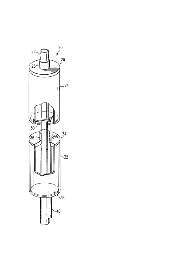
FIGUKE ~ is a perspective illustration of a dipole
radiator in accordance with the present invention,
FIGURE 2 is an elevation illustration of a
plurality of dipo~e radiators in accordance with the
present invention mounted on a common mast to form a
high gain, omnidirectional antenna,
FIGURE 2A is an enlarged illustration of a feed
line junction point shown in FIGURE 2,
FIGURE 3 is an elevation illustration of a
plurality of dipole radiators in accordance with the
present invention mounted on a common mast and having
multiple feed lines,
FIGURE 4 is a detailed illustration of a feed~line
assembly in accordance with the present invention,
FIGURE 5 is an illustration of a group of dipole
radiators for illustrating RF choking between the dipole
-radiators,
FIGURE 6 is an illustration of a single dipole
r~diator in accordance with the present invention
combined with a partial section of a dipole radiator
which functions as an RF choke for the adjacent dipole
radiator, and
FIGURE 7 is an illustration of an antenna in
accordance with the present invention having two dipole
radiators together with an ~ cho~e.
7 2021~7
DETAILED DESCRIPTION
A dipole radiato~ 20 in accordance with the present
invention is illustrated in FIGURE ~. ~h~ radiator 20
is mounted on a tubular mast 22. A first cylindrical
radiator element 24 is coaxially mounted on the mast 22
by means of an end plate 26 which has a bushing 28.
Bushing 28 has an interior diameter which is
approximately equal to the exterior diameter of the mast
22. In the illustrated embodiment, the cylindrical
element 24 and end plate 26 are separate units which are
bonded together by any one of many techniques including
brazing, soldering or press fit. However, the assembly
comprising element 24, plate 26 and bushing 28 can be
fabricated as an integral unit.
Dipole radiator 20 may optionally include a
cylindrical dielectric support 30 at the opposite end of
the element 24 from the end plate 26. This would
typically not be used unless the length of the element
24 exceeds 8 inches. For shorter lengths, the
additional mechanical support provided by the dielectric
support 30 is not required. The dipole radiator 20 is
further equipped with a second cylindrical radiator
element 32 mounted coaxially on the mast 22 offset from
the element 24. The radiator element 32 is provided
wlth an end plate 34 and a bushing 36. The element 32,
plate 34 and bushing 36 correspond to the element 24,
plate 26 and bushing 28 described above. The radiator
element 32 is further provided with an optional
cylindrical dielectric support 38 at the end of the
radiator element 32 opposite the plate 34.
A feed line 40 provides a radio frequency (RF)
transm~ssion path for both transmitted signals and
received signals for the dipole radiator 20. Note that
feed line 40 extends along the exterior surface of the
8 2021057
mast 22 but within the cylindrical radiator ele~ent 32.
The fe~d line 4~ has a center conductor 42 which is
connected at the center of a wire 44 that extends
outward from the conductor 42 and is connected at
substantially opposite edges of the radiator element 24
in a proximate area of the end of the element 24
opposite the plate 26. The wire 44 is preferably
soldered to the conductor 42 and soldered to the
interior of the eiement 24.
Further note that the end plate 34 has an opening
34A which permits the feed line 40 to pass therethrough.
The bushing 36 has a slot opening therein which is
aligned with the opening 34A. The feed line 40 passes
through the slot in the bushing 36.
srass is a preferred material for the mast 22,
cylindrical radiator 24, end plate 26, bushing 28,
cylindrical radiator 32, end plate 34 and bushing 36.
These units are mechanically bonded or soldered together
in such a fashion that there is a DC electrical
connection between all of these elements. The mast 22
is securely connected to an earth ground thereby
establishing a DC ground for all of the components of
the dipole radiator 20. This configuration provides
very good lightning protection for the dipole radiator
20 because any lightning discharge is directly shunted
to ground rather than being permitted to arc across an
isolated conductor thereby causing damage.
The spacin~ between ~he end plate 34 and the bottom
of the cylindrical radiator element 24 is preferably 2%
of the selected center frequency of operation for the
dipole radiator 20. The combined length of the radiator
elemen~ 24 and its radius is preferably equal to
approximately one quarter of the wave length of this
selected center frequency. Further, the ratio of the
9 202~057
diameter of the mast to the ~iameter of the cylindrical
radiating element should be less than .5. While the
dipole radiator 20 may be operated at many frequencies,
the present embodiment is designed for principle
operation in the frequency range of 100 mhz to 1 ghz.
A further embodiment of the present invention is an
antenna 48 illustrated in FIGURE 2. A detail of the
feed line structure is further illustrated in FIGURE 2A.
This antenna lnc?udes a plurality of dipole radiators
52, 54, 56 and 58. Each of these dipole radiators is
the same as the dipole radiator 20 described in
reference to FIGURE 1. The dipole radiator 52, 54, 56
and 58 are spaced along a tubular mast 50 from each
other by a distance which is approximately one quarter
wave length for the selected center frequency.
The top of the mast 50 is provided with a threaded
connector 60 for connection of additional mast sections
that carry similar dipole radiators.
An opening 62 is provided ln the mast 50 at a
position in the center of the group of dipole radiators
52, 54, 56 and 58. A primary feed line 64 is positioned
within the mast 50 and extends downward from the opening
62 to the base of the mast 50. A connection line 66
extends from the primary feed line 64 to a connection to
a-secondary feed line 68 which has an upper segment feed
line 68A and a lower segment feed line 68B. A tuning
stub 7~ is connected to the upper end of the main feed
line 64 at the junction with line 66 to provide
impedance matching between the main feed line 64 and the
secondary feed line 68.
The primary and secondary feed lines, such as 64
and 6~ can be coaxial lines which have a metal outer
conductor which can be soldered to the mast, such as 50,
for support.
2021057
A single one o~ t~e dipole radiators, such as 52,
54, s6, and 58 has 0 DB gain. A combination of two of
these dipole radiators provides 3 DB gain. The
combination of four of the dipole radiators, as shown in
FIGUR~ 2 proY~d~s ~ DB of gain. Each doubling of the
number of dipole radiators provides an additional 3 DB
of gain for the antenna.
A still further embodiment of the present invention
is an antenna 80 which is lllustrated in FIGURE 3. This
antenna includes a tubular mast 82 and a plurality of
dipole radiators 84, 86, 88, 90, 92, 94, 96 and 98.
Each of these dipole radiators is similar to the dipole
radiator 20 described in reference to FIG~RE 1. This is
a quad dipole antenna. Radiators 84 and 86 are a first
antennas, 88 and 90 is a second, 92 and 94 is a third
and 96 and 98 is a fourth antenna.
Antenna 80 is further provided with an RF choke
100. The choke 100 has a physical configuration the
same as the combination of the cylindrical radiator
element 32, end plate 34 and bushing 36 shown in FIGURE
1. The choke 100 serves the function of suppressing RF
energy produced by the dipole radiator 98. The RF
choking aspect of the present invention is further
described below in reference to FIGURE 5.
- The antenna 80 has four feed lines 110, 112, 114,
116. All four of these feed lines extend through the
center of the mast 82. The feed line 110 extends from
the base of the mast 82 upward to an opening 124 in the
mast 82 where the feed line 110 is connected to a
secondary feed ~ine 126 that extends to the dipole
radiators 96 and 98. The feed line 112 extends from the
base of the mast 82 upward to an opening 128 which is
located between the dipole radiators 92 and 94. A
secondary feed line 130 is connected to the primary feed
- 11 2~2~0~7
llne 112 at the opening 128 and extends in opposite
directions for connection to the dipole radiators 92 and
94. The feed l~ne 114 extends upward to an opening 132
in the mas~ 82 located between the dipole radiators 88
and 90. A secondary feed line 134 is connected at the
opening 132 to the main feed line 114 and is further
connected to the dipole radiators 88 and 90. The feed
line 116 extends upward to an opening 136 in the mast 82
where it is connected to a secondary feed line 138 that
is in turn connected to the dipole radiators 84 and 86.
The various secondary feed lines are connected to the
dipole radiators in the same manner as shown in FIGURE 1
and the feed line junctions are as shown in FIGURE 2A.
The feed lines 110, 112, 114 and 116 are internal to the
mast 82 and the secondary feed lines 126, 130, 134 and
138 are external to the mast 82.
The antennas 48 and 80 described above are
preferably mounted within a tubular dielectric housing
(not shown) which provides protection from weather as
well as provides mechanical support. This housing is
preferably made of plastic or fiberglass.
A still further aspect of the present invention is
illustrated in FIGURE 4. This is directed to a feed
line conf~quration. A structure 150, which is a portion
of an antenna that can include the dipole radiators
previously described, includes a hollow tubular mast
152. A primary feed line 154 extends from the base of
the mast 152 up to an opening 156. At the opening 156
the primary feed line 154 is connected to a secondary
feed line ~58 which ~as an upper se~ment feed line 158A
and a lower seg~ent feed line ~B~. The se~ondary feed
line 158 is positioned on the exterior of the mast 152.
The upper segment feed line 158A extends upward from the
opening 156 and is connected at the opposite end thereof
~ 12 2021057
to a tertiary feed line 160 which has ~n upper segment
feed line 160A and a lower segment feed line 160B. The
lower segment feed line ls~s is likewise connected to a
similar structure for a tertiary feed line 162.
The junction between the upper segment feed line
158A and the tertiary feed line 160 is provided with a
tuning stub 164 for impedance matching. The tertiary
feed line 160 is provided with connecting loops 166,
168, 170 and 172 for connection to dipole radiators,
such as radiator 20 shown in FIGURE 1. The dipole
radiators are shown as dashed lines. (please include a
dashed line showing where the dipole radiators would be
positioned on mast 152)
A still further aspect of the present invention is
illustrated in FIGURE 5. The configuration of the
present invention has the particular advantage that one
element of each dipole radiator functions as an RF choke
for the adjacent dipole radiator. In a multiple dipole
radiator configuration, each dipole radiator not at an
end can have an RF choke both above and below it. In
FIGURE 5, there are shown dipole radiators N-l, N and
N+l. These dipole radiators, their connection to the
mast and feed line connections are the same as shown in
FIGURES 1-4. Note that for the dipole radiator N, the
lower cylinder radiator element of the upper dipole
radiator N-l functions as an upper RF choke. Likewise,
the upper cylindrical radiator element of the dipole
radiator N+l functions as a bottom RF choke for the
dipole radiator N. Each dipole radiator produces RF
curr~nt which u~wards and downwards along the antenna.
The adjacent cy~indrical radiator elements, due to their
ground ~o~nec~ions to the mas~, serve to choke off this
RF current from an adjacent radiator. This action
improves the antenna pattern.
-
13 20~0~7
A further configuration of the present invention is
illustrated as an antenna 174 in FIGURE 6. The antenna
174 includes a tubular mast 176 and a dipole radiator
178, both the same as described for mast 22 and dipole
radiator 20 in FIGUR~ l. ~owever, the antenna 174 is
further provided with an RF choke 179 at the lower end
of the mast 176. The RF choke 179 has a structural
configuration that is the same as the combination of the
cylindrical radiator 32, end plate 34 and bushing 36
shown in FIGURE l. Choke 179 serves to suppress RF
current produced by the dipole radiator 178.
A still further embodiment of the present invention
is an antenna 180 illustrated in FIGURE 7. The antenna
180 includes a tubular mast 182 which has mounted
thereon dipole radiators 184 and 186. The dipole
radiators 184 and 186 are the same as the dipole
radiator 20 described in reference to FIGURE 1. The
antenna 180 further includes an RF choke 188 which~is
essentially the same as the choke 179 shown in FIGURE 6.
The choke 188 provides for suppression of RF energy
produced by the dipole radiator 186.
The structure of the antenna of the present
invention is easier to manufacture and repair than
previous antenna designs, such as that shown in the
MacDougall patent. This is principally due to the feed
structure which places the secondary and tertiary feed
lines on the exterior of the mast and to the direct
metallic connecting of the cylindrical radiators to the
mast.
Although several embodiments of the invention have
been illustrated in the accompanying drawings and
described in the foregoing detai-ed description, it will
be understood that the invention is not limited to the
embodiments disclosed, but is capable of numerous
14 2021~7
rearrangements, modifications and substitutions without
departing from the scope of the invention.